

Radian
-
Posts
2586 -
Joined
-
Last visited
-
Days Won
15
Everything posted by Radian
-
It's quite a messy picture and changes a lot throughout the day. The central peak is clearly the recharge of numerous capacitors via bridge rectifiers around the house. I think the current to the right of the peak will be from the more inductive loads like the fridge freezers and fans. When I put on a big resistive load like oven and kettle combined, its a bit more like you would expect. I just captured this now and only one freezer is on: Doing this, I have just spotted the small phase shift between current transformer and voltage conversions. Expecting the current to lag I thought I'd got the sampling sequence the other way around to compensate but I need to check that.
-
This is a good reason to base the thing on a microcontroller like the ESP's rather than an embedded OS running on an SBC like Raspberry Pi. Once the code has been flashed in there's no ongoing maintenance required. A box with a flying lead is plugged into a 13A socket near the meter and another interrupts the cable going to the immersion. Simple as. I think that's what make things a bit more difficult. If the energy content of the meter buffer (bucket) is tracked on a cycle by cycle basis then at the end of any given cycle a decision can be made whether to start emptying it by applying the dump load. This is why I'm striving for low latency. Having energised the dump load, the subsequent cycle measurement(s) will reflect the effect that both the dump load and natural house loads are having and the buffer can be allowed to drain to some minimum threshold before letting it refill by removing the dump load. I can visualise this and code for it but as soon as I decouple it from the cycle by cycle basis and respond in other time bases I find it gets very confusing!
-
A little update. The Power monitoring section is now complete and sampling away nicely. Actual 240VAC and current is being captured at around 150 samples per cycle and looks like this (as downloaded from the webserver running on the sampling ESP32): The tips of my AC really do look blunted like that as confirmed by x100 probing direct with a scope. When I was looking at the output of a transformer I took it the distortion was due to the saturation of the primary but no, the voltage waveform is really like that. Who knew? Anyway, multiplying all the VI sample pairs over each cycle and scaling their sum with a suitable calibration value is giving me a power reading that agrees very well with both my utility supplied meter and a PZEM-004T V3 Energy Monitor I installed next to the ESP32 as a second opinion on the power measurments I'm making. Only unlike those meters, mine gives me the 'holy grail' of -ve power when pushing current into the grid (the utility meter just clips at zero and the PZEM always shows a positive value even when actually negative)) So the next part of the process is to multiply the power for a complete cycle by the cycle period (20ms) to get the quantity of Joules going in or out of the meter. The trick to dumping only the energy that would go back to the grid is to let out up to a maximum of 3600J then keep pulling it back in (into the dump load) if necessary. 3600J is supposed to be the threshold at which the meter records a transaction so can be used as a buffer to give an opportunity for real loads to consume the excess but if there are no such loads then the signal to send power to the dump load is sent. Normally the signal would be hard-wired to a Triac or SSR to switch on an immersion heater but I have a different plan. What I want is to be able to turn on multiple loads anywhere on the house wiring when the surplus is available. Then individual appliances can decide for themselves if they could use some power. A wireless solution is ideal so I started experimenting with MQTT. Unfortunately there seems to be too much latency between signalling that excess is available and acting on the message. Ideally the response should happen in the next cycle (20ms max. later). I also tried websockets but the complexity of using the LAN was beginning to seem like a bad idea. As I mentioned earlier, I had thought about using mains signalling like that used in X10 devices. So now I'm building the hardware to 'tag' each mains cycle for consumption when required. X10 protocol is too slow to use house codes and other niceties so I'm thinking of just putting a burst at the zero crossing and qualifying it with a non-standard burst width in addition to a belt & braces check that we actually want energy diversion using MQTT messaging as a 'gate'. I've already built the 120kHz receiver and it's all quiet in this band on the mains. I guess nobody uses X10 these days anyway!

-
Can you bung me £10k so I can redo my biggest deck in composite? Did a small one outside the living room one 25 years using Douglas Fir and it's still mint. About 15 years later I built a 12m x 3m one at the southern end of the garden using B&Q deck boards and it's completely shot through.🙄
-
You're mellow today 😁
-
 Michael Heseltine privatised the BRE back in 1997. Call me a cynic but I would expect there to be a string or two still attached.
 -
Only problem with that is it restricts the airflow so if timber will rot away much faster. I've come to understand the importance of having significant ventilation under timber decking. 🙄
-
Ah, so the assumption is that a house undergoing improvement was probably built to a lower standard than if it were to be built now and this measure will balance things out a bit. I honestly don't think the folks behind this are bright enough to think of that. The Lobbyists from the construction and development industry simply stuck their oar in at some point and those without such a powerful voice (nobody's listening to them anyway) would be easy game for assistance in meeting international obligations r.e. carbon reduction.
-
50% self used sounds pessimistic but it's probably too optimistic. It's difficult to use every drop of power and not a Watt more than you need to - even with a solar diverter to immersion. The coincidence of lower heating use and higher Solar supply in the summer is a PITA. Batteries are the go-to solution but push the ROI out twice as far. I personally favour a smaller PV array of, say, no more than 3kWp and both divert to immersion as priority and to Air Conditioning as a second way to burn off excess. Both are controllable and perform useful work.
-
Yes it can be fun to see useful energy being generated at your own property. But £6K buys 20 Megawatt hours of electricity at todays prices. I could munch through that in 5 years but it might keep most people supplied for 10. If prices go up to 50p/kWh and stay there for 5years of so it starts to look more viable. But that's a big if.
-
Doesn't this just reflect the fact that we are one of the few countries to have LNG terminals that can handle deliveries? While the rest of Europe builds its capacity we're doing the importing and currently using CCGT and the DC interconnect to export electricity as much as we can while the demand is there?
-
£1.40 per Watt Peak. Seems like the sort of figures I saw in the 1st quarter of this year. Probably reasonable given the problems getting quotes these days. Can't remember the last time it was £1/Watt.
-
So you never noticed the bricks being damp even though they were. Shows up a treat now. To me the damp at the bottom looks mostly like rain splashing back up from the paving. I say that because the stripe on the RH wall gets wider further forward (the opposite of the slope of the ground). In fact the wall looks well clear of the soil at the very front where the damp is at its deepest. As for the capping joints they could easily be raked out and repointed with a strong SBR added mortar mix to make it waterproof. But if there's no horizontal/vertical DPC there's always going to be some damp in the render. You may be able to mitigate the problem with a silicone topcoat. I expect someone else here may step in with some advice on that.
-
Static electric, living in a Faraday cage?
Radian replied to Jilly's topic in General Self Build & DIY Discussion
Foil backed insulation and low E glass can massively attenuate RF. That's to be expected. But when you describe a buzzing when touching light switches, that's odd - unless they are touch switches - in which case you will feel a tiny AC leakage current which is part of their design. I'd describe it as being more like feeling a velvety texture when you dab a finger on the metal parts. A similar leakage current will be created by certain electronic equipment in their power supplies. These have capacitor filters leaking a little current from live to earth so if your earths are not properly bonded you may get "that felling" from touching the metal parts. This ought to be investigated. With great respect I would say you may have a genuine electrical issue but may be incorrectly linking the headaches and thinking issues with the electrical situation. There are a variety of other well known causes for these kind of symptoms. -
-
I've got a theory about that... 🙊
-
Weird plaster issue at 400mm centres
Radian replied to Adsibob's topic in Lofts, Dormers & Loft Conversions
I often wonder if pops might happen because of drying-out. Our houses internal timbers went through a very wet winter with no roof. The pops only started appearing some months after we moved in. If the surface of the timbers shrank back towards the centre then plasterboard fixings (nails in our case) might be anchored in dry wood while a small gap opens up between PB and timber as the surface layers of the wood dries out. The chipboard flooring was even worse as it started creaking and groaning against the nails (ring shanked, no glue). Ah the good old days before expanding glue products. Further evidence might be that the floor got so creaky that the builders came back, lifted all the upstairs carpets and threw hundreds of screws in. It fixed it perfectly - for a year or so. Since then it's gone back to walking on a comedy floor. -
Fond memories of those. I remember when we used to be shit scared of the General Post Office who were in charge of that kind of business. I wonder how many people today would believe that.
-
I agree. I even avoid probing live terminals with a multimeter unless absolutely necessary. I've got a 240V isolating transformer to float circuits under test - which at least reduces the chances of shock from a careless stray touch. Also allows scope earth to connect to Neutral without triggering the RCD. Does this advance humanity or not I wonder?
-
Actually, I must have been something like 14 or 15 as I was flogging home-made sound to light converters to my class mates well before I did my O-Levels. Funnily enough I found one in the recent attic clear out. Should have taken a photo. Rats.
-
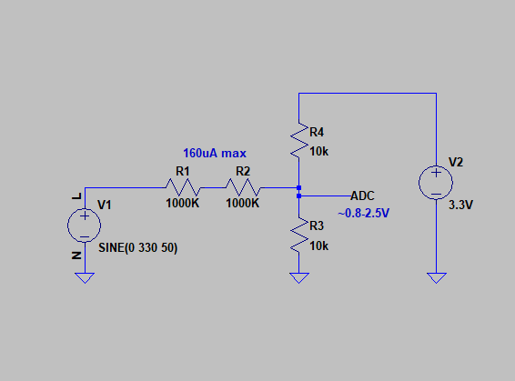
Uh oh! It's live mains we're talking about so I don't know where to stand on this request! I've been wiring things directly to the mains since I was around 16 years old and kind of have a second sense about working around lethal voltages. There's nothing physically wrong with doing it, but given the dangers there's usually a lot of pressure to use alternatives involving transformers or opto isolators. But this is one case where direct connection can be desirable. There are plenty of examples on the web such as this one but using an OpAmp, like the one in that link, is optional for a real bargain basement mess around. My initial test circuit is about as simple as you can get: Anyway, it illustrates the point. Actually, to put things into perspective, I have some Touch Dimmers around the house that use a couple of high-value resistors connecting the touch plate to the phase control circuit at line voltage. You get a little tingling sensation off these things but the uA current through the body to Earth is harmless enough for them still to be sold on the open market. Same thing as above really.
-
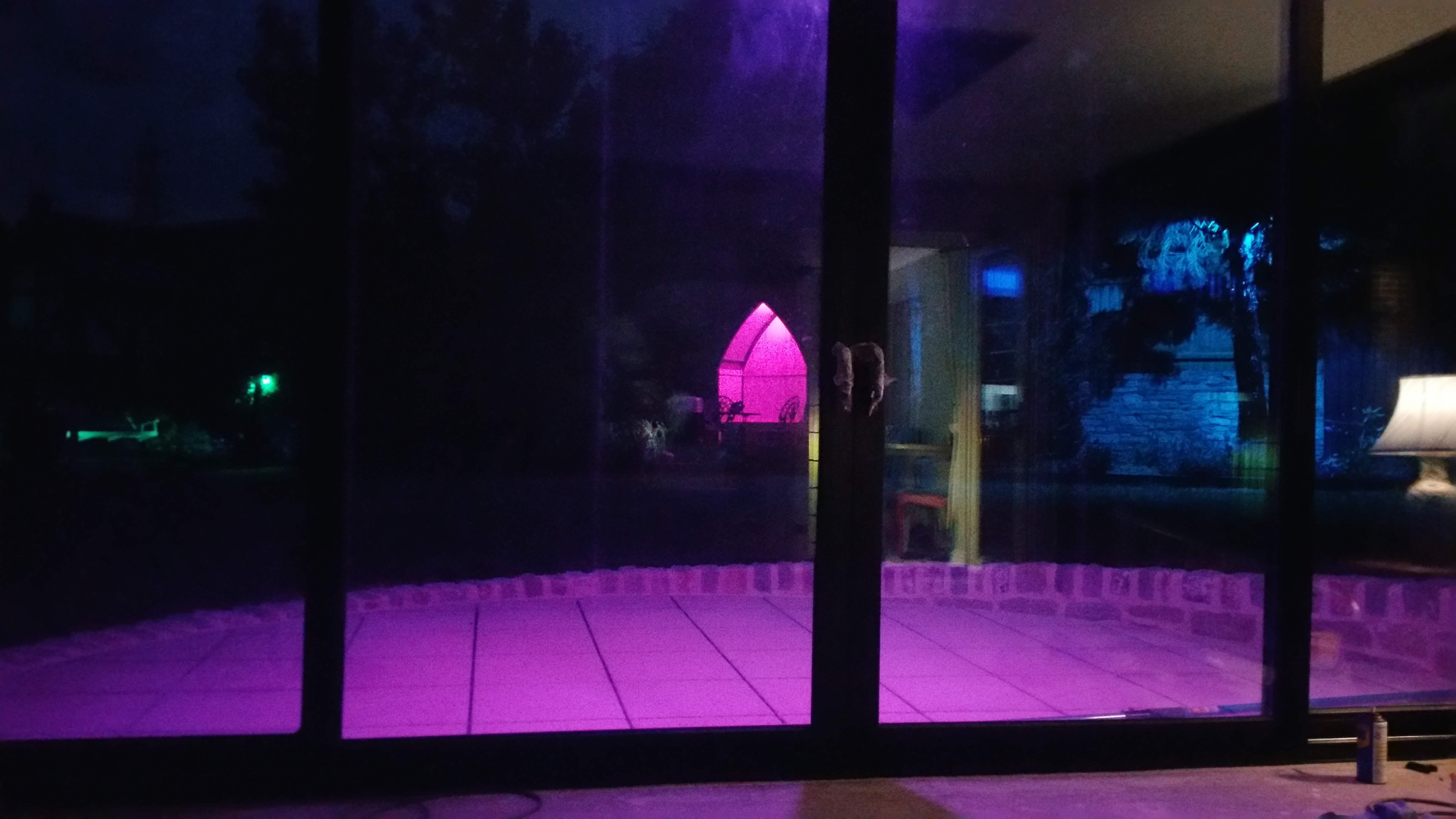
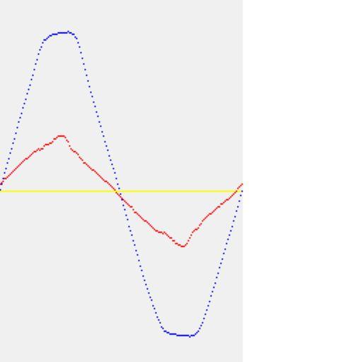
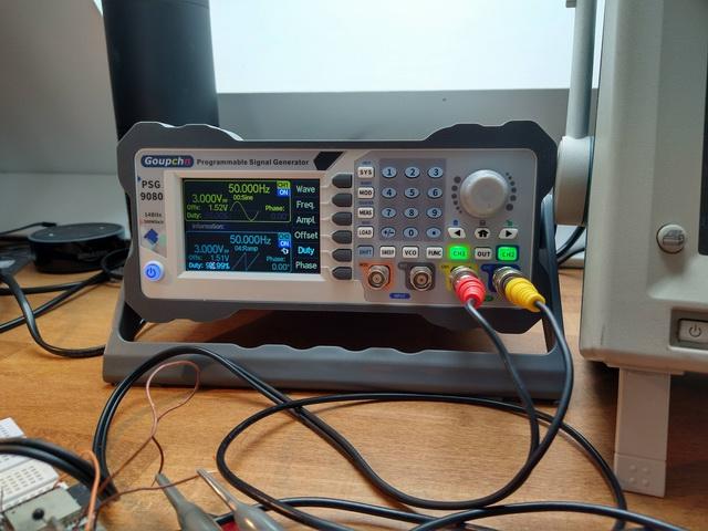
Small progress report. Still sticking to the plan regarding choice ESP32 as processor. One of the reasons is the ability to do firmware updates over WiFi so once it's in place I can tweak code from anywhere. This also provides full galvanic isolation so I can measure the 240VAC directly with reference to Neutral and dispense with the sinewave distortion and phase shift inherent in transformer coupling. While there are specialist transformers specifically for this purpose it's a bulky solution. People in parts of the world on 110VAC are lucky as they can cheaply wire transformers with split primary 110V windings in series and get non-staurated AC at half the output voltage for measurement purposes. A series pair of 1meg resistors (for safety) as part of a voltage divider with 10K is all it takes to turn 240VAC into a 3V swing for the ADC. Another benefit of having an embedded web server at the end of a huge huge air gap is that I can create scope-like images of the waveforms in a bitmap (with an arbitrary number of traces) to keep an eye on everything. Example proof-of-concept bitmap just collected from my browser: Oh dear, the ESP32 ADC isn't very linear. That's a pair of test waveforms from this function generator: Still, it's a start.
.gif.6e6b231c8952a0112d8241d64ee17b76.gif)
-
It certainly us. 👽
-
Ivt air x 50 ashp ebay bargain or .... not
Radian replied to Jacob's topic in Air Source Heat Pumps (ASHP)
And it's nearly always just the filter capacitor that needs replacing on the switch-mode PSU - a part that you can buy for 50p -
A very kind offer indeed but it'd be a shame to butcher an Iconic bit of 90's renewable energy tech like that! I bet it'd get snapped up on Ebay. Actually it has given me a very useful idea - the Sunny Boy comms uses X10 style mains signalling and that could be a simple low-latency control method to fire-up the immersion (sort of like tagging individual mains cycles for consumption). I dabbled with that in the 90's so could dust down some old kit to try if and when I get that far.

