
Radian
-
Posts
2586 -
Joined
-
Last visited
-
Days Won
15
Everything posted by Radian
-
Breaking bad style?
-
I think that's very interesting indeed. Could it be that chopping the solar divert power into bursts (over a period of several minutes to illustrate my thinking) could kick off turbulence? Some experimentation is in order!
-
Have you looked at the Solcast API?
-
I've been thinking about all the little things that might benefit from surplus power. My distributed mains signaling system easily enables me to switch a wide variety of different loads anywhere the mains is available: Electric Towel rails wouldn't add too much unwanted heat in the house if there was a moisture sensor gating their operation. PIV is another candidate. And what's that hot water circulation thing called? Y'know, where you have a loop circulating HW to taps driven by a pump to ensure instant HW? I tend to think they're a bit of a lossy luxury but if the cylinder is already max'd out and there's still power to spare, why not pump it around some? I've already got my double Makita battery charger set up to come on automatically. Sounds silly but it actually draws around 400W for half an hour if there's a couple of empty 5Ah batteries sat waiting on it. Every little helps 😇
-
That's what I was wondering about. Back in 1980 something I bought some 5L containers of a two part product that mixed in equal quantities expanded by 100 fold. Used it everywhere (not always intentionally). I guess it was Polyurethane. Put up some formwork around the outside and fill the whole base.
-
Aw, nice old blog there. More bedtime reading. Yep, Ideally I'd have had two immersion ports on my shiny new cylinder but alas not. A series/parallel switching system using two bog standard heaters would have covered all bases nicely and cheaply. At the moment I've only got a spare half kW doing nothing but making an occasionally slightly embarrassing increment in my export register (just a little over 2kWh so far, but difficult to explain away), so a small immersion would be the best fit. My homebrew diverter is just starting to take care of the embarrassment but it's currently dumping unwanted heat via a 750W convector heater in my already scorching workshop 🙄
-
That's more like it. Not heard of that company before. Great selection! Basement no, kitchen yes. The under-cupboard LED strips are pretty much always on despite having windows facing NW, NE and a small but stylish SE facing vertical slot window. I've yet to verify that a 3kW element would cause flicker but I just wanted to see what my options were if it did.
-
Ouch! But thanks anyway. True, but a bit bulky for the airing cupboard. Ha yes! But I've already built my own. The problem with driving a 3kW element is that power control is either burst mode (effectively PWM using whole cycles) which can mean on/off cycling over sub-second intervals - which can produce flicker in lights. Other modes have their own issues - phase angle control is just nasty at these power levels and true AC PWM is nightmare expensive compared to Triac switching. Which is why most DIY solutions use burst. Just thought a smaller immersion might be better for this but it turns out they're super uncommon. Oh well.
-
I'm looking for an immersion that's less than 3kW. According to this Tesla data sheet TIH642 is 1kW and marked "Recommended for solar". Perfect. But nowhere seems to stock it and it doesn't even come up in a search on the Tesla webshite. Anyone managed to find such a beast anywhere?
-
I doubt if you would need to batten the floor. Just lay rigid PIR straight over and top with ply or flooring chipboard. The load is spread over the large contact areas. Even just 50mm would make a big difference. Might want to do something to prevent vermin chewing into it from below though? Superfoil not much use especially if squashed flat.
-
Yes, you and Selçuk Bayraktar ☺️
-
How does that play out? Is there an OEM app that finds it on the LAN and communicates entirely locally - or have you got hold of the API and rolled your own control/monitoring system?
-
Thanks for posting your write-up - like others here I'm working my way through it. I can already see plenty of good engineering practice - what other projects have you done before this one? I'm guessing this isn't your first major build.
-
There you go! That's what I'm talking about 🤩 Never mind us here, the entire world needs a write-up! I do appreciate that's quite a big ask, but at the very least a few more photos please (or pointers to anywhere else you may have shown this).
-
Where's the fun in that!
-
A Noble goal! DIY inverter and controller - yes, certainly but it's take a bit more than a scrapyard freezer to cobble the rest together. I keep meaning to work out what the heating capacity would be when configured that way around. Care to save me the trouble? I'm busy working on my PV diverter this weekend. Oh, and for added industrial realism, a COP between 3 and 4 and a flow temp of 55C would nearer the mark for a £1K product.
-
£1k would be more realistic for both manufacturers and consumers. Perfectly do-able IMO.
-
Thanks for your comments. What I've cobbled together meets my needs quite well and the burst firing keeps harmonics to an absolute minimum. As you know, the downside of burst firing is flicker but just how much of an issue is when the diversion is only going to take place on bright sunny days. Yes it may not meet acceptable volt-drop limits but I'm not looking for a commercially viable solution here. Out of curiosity I might nip over to next door's house with a scope to see how far both the X10 and volt-drop reach. Luckily they have all three phases unlike my singleton. I'm now adding an ESP32 to the load switch so I can monitor the actual energy being diverted and qualify the mains signalling. It will also provide a fall-back if the mains signalling isn't working: for display purposes I get an update over MQTT once a second for the number of Joules in the bucket so if it looks like it's about to overflow it can fire-off the Triac and send me an alert that it's in belt & braces mode. I did try using MQTT at 10 samples per second but it bogged down the whole process. I'm using AsyncMQTT but haven't tried putting the sampling into an independent task. Having some intelligence in there also means I can eventually prioritise any number of diverted loads from a schedule. Any batteries would probably be a higher priority for example. Not heard of the Cyclo system, most intruiging! I'm always amazed that you can poke a few +/- volts onto the mains and not have it totally absorbed by the scores of loads around a house. I wouldn't want to try putting a brief dead short on the supply though!
-
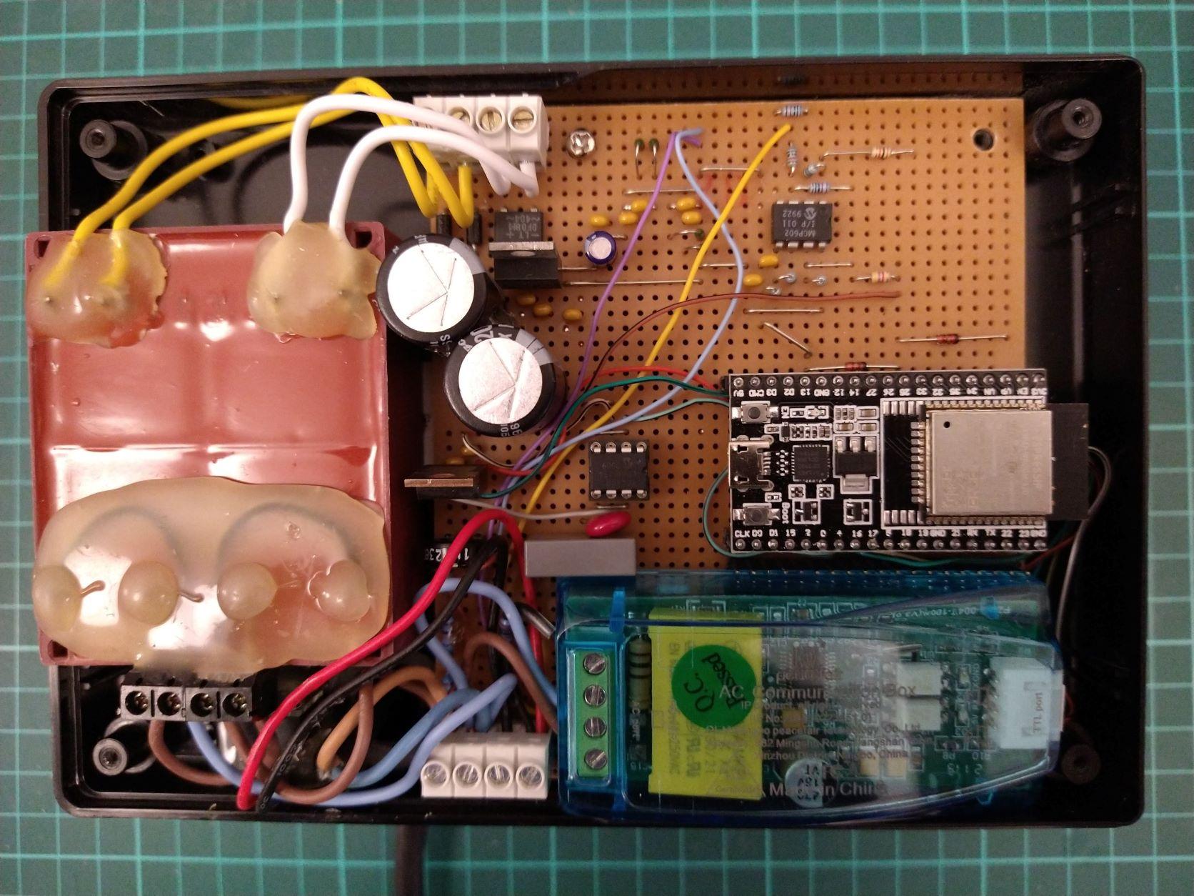
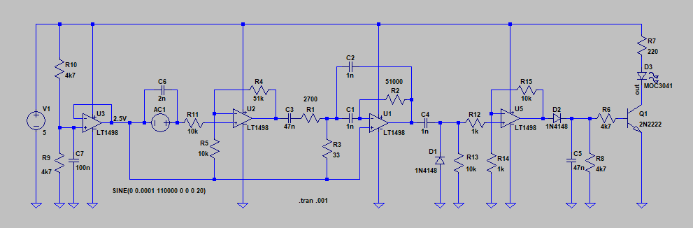
Point to point is how I've built the Triac load driver in the absence of a PCB: The 120kHz signaling is up and running now. I've tested it driving the Triac opto coupler (MOC3041) direct, i.e. the measurement unit puts a 1ms burst of 120kHz just before the zero crossings of each cycle it wants 'burnt off' and the above unit can plug in anywhere around the house to switch those cycles into a suitable resistive load. The 120kHz signal is represented by AC1 in the above circuit. It's actually the secondary of a pulse transformer tuned to the signal, with the primary coupled to the Live mains via an X2 capacitor and fusible resistor (not shown). After a bit of gain the signal goes through a high Q band pass filter followed by an envelope detector. So this circuit along with the Triac could form a self contained, remote controlled load dumper. I could easily and cheaply reproduce it and dot them around anywhere with a suitable load. However, it's not gated by any other enable apart from the signalling bursts. It hasn't yet fired off on any noise and the quiescent output from the signal conditioning stages looks very quiet - but I think I'll add an ESP32 to the unit to use MQTT just to verify that load dumping is supposed to be taking place. Pity really as it's so simple otherwise.
.thumb.jpg.2e7ac29c97e5db2b20db1e829e9483e8.jpg)
-
So it seems that retrofit CWI should also be done along with updgrades to ventilation otherwise the original ventilation may well be insufficient to prevent condensation. Seems counterintuitive because the CWI is done to reduce heat loss through walls (hence make them warmer) but they're still going to be one of the first interior surfaces to fall below the dew-point. It seems to make the whole thing a nonsense.
-
I've been reading again through the House of Commons debate on cavity wall insulation that took place in 2015. I'm starting to think there's another potential issue in addition to the obvious problems posed by rain penetration. Could the build-up of mould and damp on interior walls people are experiencing following installation of CWI be due to the loss of air circulation in the cavity? I'm always complaining about the draughty dry lining that issues cold air around light switches and sockets but this is also indicating an air exchange that will be transferring moisture from inside air, via the cavity and ventilated attic, to the outside. If CWI effectively stops this then other measures will be required to control moisture levels such as MV or better still MVHR. If it's just down to opening more windows does it not defeat the purpose of the insulation?
-
So it turns out SWMBO has organised a visit by a surveyor for the local Housing Authority after finding that our household is eligible for an ECO grant.😵 I guess it's some consolation for getting old but It seems odd for someone to show up at our sprawling 4-bed detached property and size us up for a hand-out. I'm right in the middle of the process of adding loft insulation, which does not meet standards as it happens. I'm just taking my time and some areas are just 100mm or less deep, but I think I'd rather finish the job so I'm wondering if to point towards our empty cavity walls instead... The main house has a two lightweight block leafs with the outer one clad in sandstone. The cavity between the blockwork is only around 50mm wide and we're in zone 1 where penetrating rain is an issue. I know the stonework sometimes gets thoroughly saturated but have no idea what happens inside the cavity. All I know is that we've had no damp issues inside. I want to know what questions I should be asking about this as the nightmare scenario is becoming yet another victim of Inappropriately installed Cavity Wall Insulation The other concerns I've voiced before about CWI for our property are that the water table is very high such that there is sometimes water coming up to around one block below the DPC on two sides of the house. I remember peering down at it when the house was at beam and block stage. There's nothing to stop a cavity fill dipping down into this as far as I can see - so wicking would be a problem with some materials. EPS beads are supposed to be a safer bet but then we also have a location where all the house electric cables cross through the cavity from one wing to another and there are well known issues about PVC and PS getting jiggy - so I'm not sure if that should rule it out or not. I'm starting to dread the visit now.
-
If I was buying battery kit from China I'd stick to lithium iron phosphate (LiFePO4 AKA LFP) batteries as they are significantly safer than regular lithium ion (NMC, NCA). The economics tend to drive the manufacturers more than safety factors and LFP's are more forgiving to design for.
-
I find it quite fascinating. The project is a nice intersection between the full stack of EE disciplines. I think I'm covering all the territory by having a LAN-centric design which gives me good visualisation and control and a chance to flex a bit of analogue design muscle because the DIY projects I've seen tend to just poke a resistor biased transformer output straight into an ADC input. I'm making full use of the air-gap afforded by the WiFi connection and 'riding' the mains voltage directly. The mains is also being used as a low-latency communications channel with the power switch which is, I think, quite novel. The prototype unit in development. Even though the circuit potentials are referenced to the mains neutral, I'm still using a split secondary transformer to derive separate DC voltage supplies for the analogue and digital sections. The PZEM power measurement unit is bottom right. I'm only using it to confirm my results and may remove it eventually. I'm sharing the same Current Transformer that came with it. Just to the left of the ESP32 module is an 8-pin DIL mosfet gate driver that makes an excellent 120kHz mains modulator (coupled with a 0.1uF X2 rated capacitor). Not much else other than a couple of linear regulators and a dual OP-Amp for signal conditioning.

-

I’m confused about ubiquiti
Radian replied to Adsibob's topic in Networks, AV, Security & Automation
There are a few auto WiFi switcher apps in the Android App store that claim to switch to stronger APs but I've never bothered risking trying any out. Why this is still an issue that hasn't been sorted out in the OS totally stumps me.
.jpg.d6172a6dc50d896468b71502122225d3.jpg)