
Radian
-
Posts
2586 -
Joined
-
Last visited
-
Days Won
15
Everything posted by Radian
-
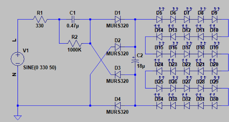
Yes, the reactive impedance of a chosen capacitor at 50Hz is what limits the current in the LEDs - exactly analogous to the choosing of a current limiting resistor for DC operation. So for a made-up example of a string of 30 white LEDs in series (many individual LEDs integrate three or more in series on a single chip so you might only count 10 on the face of a lamp) might have a forward voltage requirement of 100V, leaving 140V to be lost across the capacitor. The AC passed by the current limiting capacitor is full wave rectified and smoother by an electrolytic capacitor to make DC for feeding the LEDs without flicker. In this example, to drop 140V@0.02A (the typical forward current for a LED) requires a capacitive reactance (Xc) of 7000 Ohms at 50Hz so withXc = 1 / (2 * π * f * C) C = 0.5uF If you were to try that with a resistor it would dissipate 0.022x7000 = 2.8Watts whereas the capacitor dissipates nothing. A couple of additional resistors do usually make their way into the design - a high value (eg 1 mega Ohm) across the capacitor to bleed off any remaining charge when the lamp is removed, and a low-ohmic series resistor (eg a few hundred Ohms) to limit the current from sudden spikes that could pass through the capacitor - especially at switch-on (if your switch closure coincides with the peak of the AC sinewave). Here's one I just designed specially for you (C1 is the current limiter described above): Capacitive droppers are pretty crude!
-
It's really as simple as thinking about the analogous mechanical components Inductors and Capacitors The Capacitor is offering very little resistance to the 120kHz signal but blocks the 50Hz. The inductor does the opposite in the same way mass and springs react. Really the point I'm making here is that there's a lot of fuss (mostly rightly so) made about connecting low voltage and high voltage systems but capacitive coupling with appropriate spec. components can be considered as safe as transformer isolation. My instinctive caution is satisfied by my observation that Class Y capacitors are designed to allow weak coupling between mains live and touchable conductive surfaces. The bonus is that they provide strong coupling for high frequency signalling. Around 180 DVD players = 30mA leakage. Yes I know WAY OTT! The thing has been sat around looking for an application for years and when I tried it on the lid of the box it was exactly the same length so I concluded it was 'meant to be'. Even With a forward voltage drop of 1V @ 16A it should barely register the 16Watt dissipation.
-
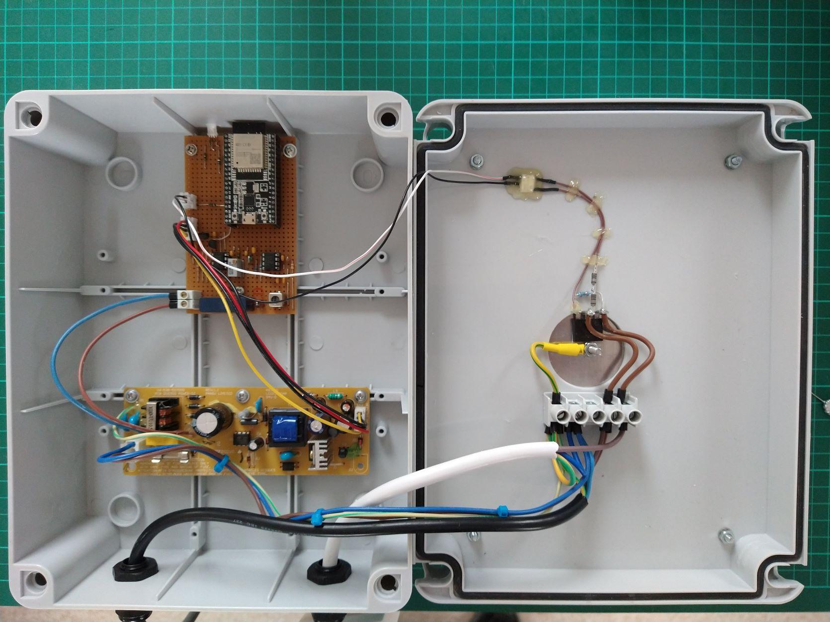
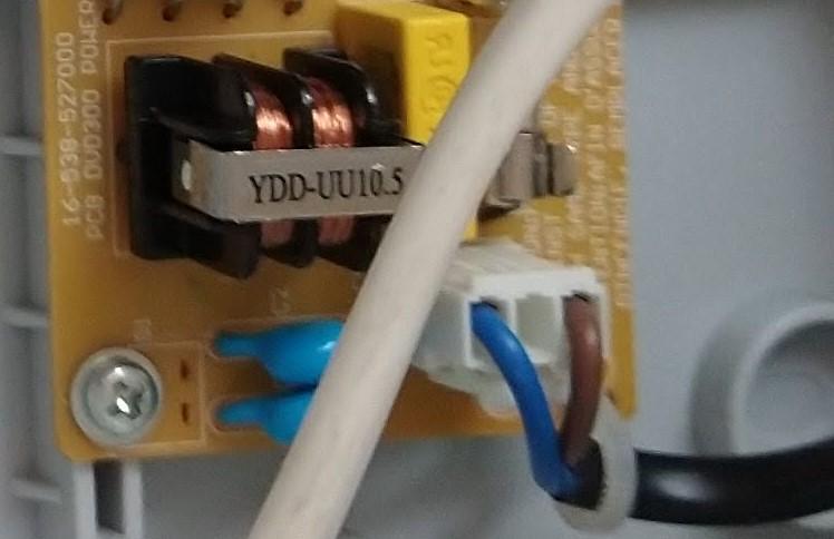
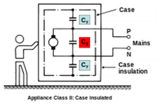
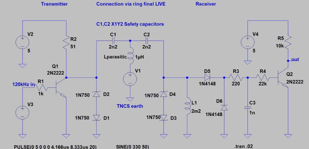
Reviewing the design of the 120kHz modulating signal that I use to tag mains cycles for diversion I've come to realise that there's a perfectly harmless way to couple the microcontroller to the AC without a a transformer. The inspiration is the typical front-end of a SMPSU like the one I have providing 5V for the circuit in the Triac box shown previously: The two blue capacitors are Class Y EMI supression capacitors wired between L & N to Earth. They are low capacitance (2.2nF) high voltage withstand (4kV) and being class Y are designed to fail open-circuit. Hence this PSU was originally in a small DVD player, with no Earth wire, and that screw coupled the common end of the capacitors to the unearthed metal case. All pretty standard: So at 50Hz the reactance of the 2.2nF capacitors (Cy) is approx. 1.5 mega Ohm therefore a tiny 160uA leakage current normally flows to earth. Higher frequency noise especially RF noise, however, sees a lot lower impedance shunting it to ground. But at 120kHz the reactance is around 600 Ohm. Intercepting the path of the capacitor to ground with an inductor (to bypass the 50Hz) in parallel with a circuit to detect the 120kHz signal results in an extremely simple receiver: Likewise the transmitter AC couples via a Y class capacitor. The microcontroller circuit and everything on the "earthy" side of the capacitors remains referenced to earth (along with any attached PCs or test gear) and so long as adequate separation (creepage) is observed where the 240VAC joins the fun - handling the low voltage side is no more hazardous than handling a typical CD/DVD player in a metal case. The back-to-back Zeners are there to clamp transients caused by mechanical switches that can interrupt the mains and produce short lived spikes that get through the capacitors. This limits the voltage to keep well within the breakdown maximums for the surrounding components. I just thought I'd write this up here for anyone that might be interested.
-

-
I could make you one but the red tape is still too onerous.
-
It was an idea I had but the builder's around these parts all appear to be booked-up for the rest of the year. I am at last, however, getting somewhere with the company that quoted me. A re-jig of the spec seems to be solving their issues. I did plenty of research on them beforehand so it's still my preferred option.
-
I got my quote on the 3rd of March when the Sun was all but a distant memory 😄 Going to have one last shot at getting it honoured.
-
I never believed a single promise and suspect that hardly anybody did. IMO The vote was cast for less excusable reasons. Anyway, I guess if there's been a significant uptick in demand here in the UK since April, then multiply that by a factor of 10 for Europeans. The current bottleneck seems to be the mounting hardware much of which appears to be produced in Germany? Maybe this will drive some indigenous steel bashers to rise to the occasion. Should be low-tech enough to match our native skill sets.
-
Well, what I meant by 'blown up' is that it's non-functioning for self builders right now. ITS: Segen are trade only.

-
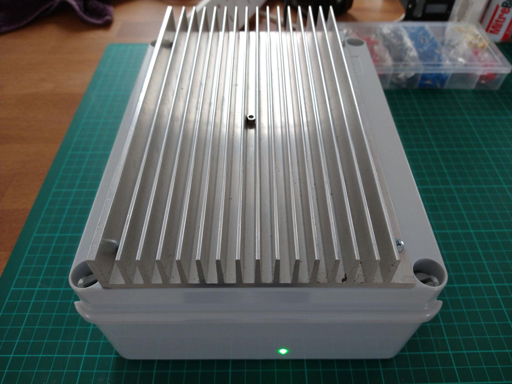
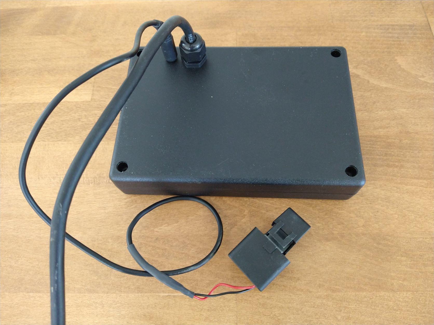
All finished now. And an animated MQTT dash info panel showing the Joule bucket filling and emptying: screen-20220613-135047.mp4 In the final configuration the Black box with the CT clamp goes next to the Electricity supply meter and has no external indicators or controls. Everything is done via MQTT over WiFi (where the power measurements are broadcast) and via real-time X10 style signalling to tag 'cycles to divert' on the mains wiring around the house. The Heatsink box goes in the airing cupboard next to the hot water cylinder and has a single LED showing green (standby) yellow (Joule bucket filling) red (Joule bucket emptying). All told very satisfying and at a materials cost of under £30 (many parts already lying around) quite a saving on buying an eddi/harvi combo. But I don't want to add up all the hours spent building it!


-
What I mean is... Back in March I had a company quote me £4200 for the supply and install of a 3kWp array plus all the standard trimmings. I agreed to the deal back then and I've been chasing them for a start date ever since. I just get excuse after excuse. To begin with it was because they were extremely busy but more recently the excuse is that they can't get the materials. I've also gone back to some other installers that I passed on and the best I could manage was a quote of £7500 for the same spec. No way. So recently I started taking to a local builder who may be able to help me out with the roof work but searching for complete kits I'm seeing odd things on suppliers websites such as mental shipping charges... Other places are showing next to no stock or confidence sapping 404 errors on pages. Anyone know of reliable companies still supplying kits?

-
Build a garden room at the bottom, put in stairs and exit onto a flat roof garden (with railings) that extends all the way up the rest of the slope.
-
Works both ways. If you point an IR thermometer or camera at a shiny surface it looks colder than a matte surface at the same temperature - hence the shiny surface not radiating away as much heat. Conduction is cancelled in those areas where the air gap remains so double win. Also this all helps in the summer when roofs get stupidly hot.
-
I've been wondering about this exact same issue for a pending job of mine. I've been contemplating just adding more bracing to create a sufficiently supportive surface for the PIR and then sheet over it all. The air gap left under the PIR is only the thickness of the bracing and, as I understand it, there's a slight benefit in having it there with regards to the conductivity and emissivity of the reflective foil layer.
-
Pity. Could have been a simple way to bring the surface level to the threshold, hide the ugly pipe & drain and make it a positive feature. Get him a cat, then build the deck.
-
Make the area into a small deck?
-

Reducing Energy Bills - How goes it?
Radian replied to Ferdinand's topic in General Self Build & DIY Discussion
Oh yes. Lucas automotive products 🤮 Found the appliance comparison site: topten -
Reducing Energy Bills - How goes it?
Radian replied to Ferdinand's topic in General Self Build & DIY Discussion
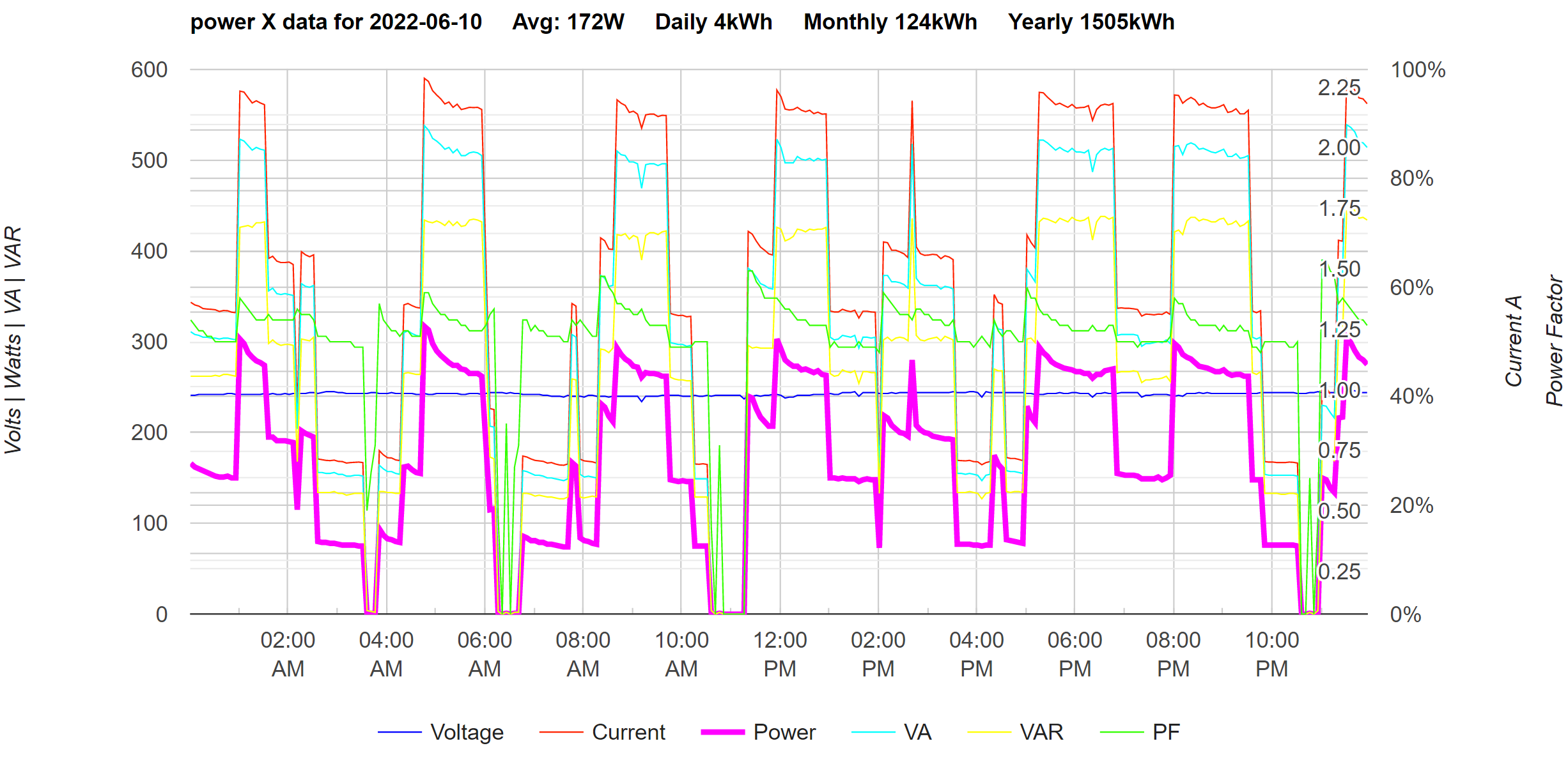
Those figures are impressively low. Damned if I can find a figure for an A-rated fridge but an A-rated fridge-freezer is around 25W average by comparison. Our freezer compressors are 80W and the fridge is around 120W when running which seems pretty typical for their age from googling around. But the duty factor is relatively high... That's all three logged yesterday via a single power metering device. Lousy PF. Good job we're not billed on VA. Kitchen was mostly around 23C yesterday. In the winter the DF goes down a bit, more like 140W daily average with a 20C ambient. Insulation is presumably better these days. I was was reading that an average fridge-freezer unit from the earlier 1990s could use over 1,000 kWh in a year. Ours date from the turn of the millenium so are a little better than that. Someone around here posted links to a wonderful website listing various new appliances by power consumption - a European site I seem to recall. Thought I'd bookmarked it but can't find it now.
-
I hear what you say, but it's really been quite a noticeable effect in our garden room on the colder winter nights - stuck out into the garden a fair way from anything else. With the UFH being so effective and heating through radiation I wonder if that's what makes the difference? I mostly felt the cold from the glass on the tops of my wrists and on neck/cheeks. That's what comes of sitting round in T-shirts when jumpers would be more sensible. The room has three fully glazed sides (two 3.8m sides split into three equal panels with the central one sliding, and the 5m rear split into four equal panels with the middle two sliding). The roof is a warm-roof construction and the glazing is all low-E but only double, not triple. Insulated floor etc. Overall it's pretty good energy loss wise.
-
Reducing Energy Bills - How goes it?
Radian replied to Ferdinand's topic in General Self Build & DIY Discussion
My tall fridge + two vertically stacked under-counter sized freezers consume around 32kWh per week. Add in 3kWh per day for the oven and that's already 53kWh. Easy to push that to 70kWh with, say 100W 24/7 vampire load from WiFi, TV, Sat etc. Not much scope for reduction if you've got to cook for and feed a family. -
Nicely observed. One thing I've discovered recently is that being in proximity to large expanses of glass in cold weather can make you feel cold despite what would otherwise be comfortable air temperatures. Emissivity apparently (fairly obviously really) works in both directions so radiating personal heat outwards has a very noticeable effect.
-
Agreed when touching a surface (or in water) but if a space is otherwise going to be unheated and the air temperature is, say, only 5C then I'm struggling to "visualise" the difference in feeling. I know what sitting in an room at 5C is like but not at, say, 20C when only heated by A2A. Funny that. I guess this is what you mean by directing the airflow away from you? Was I dreaming or was there a Mitsubishi A2A that had a thermal occupancy sensor that would do this automatically?
-
Reducing Energy Bills - How goes it?
Radian replied to Ferdinand's topic in General Self Build & DIY Discussion
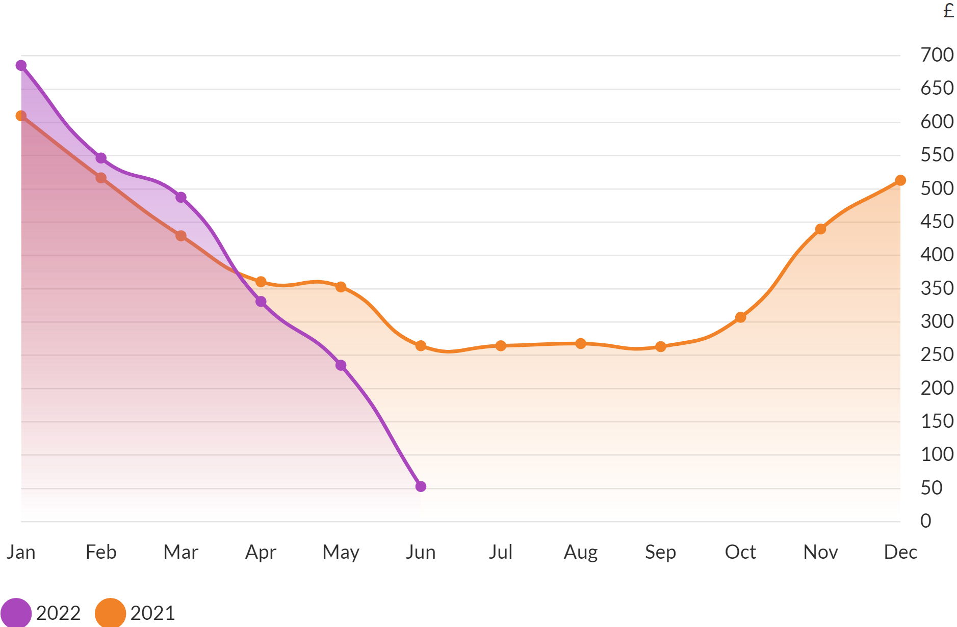
Not quite that bad. Up until April when our fixed rate tariff ended, those figures are 2.3 times more than we paid. However, the graph showing £700 for Jan would be true for our current tariff. Still, we actually paid £300 which is alarming enough. What didn't help was having a 2kW convector keeping my workshop at a constant 15C to measure then heat loss (as an experiment). -
Reducing Energy Bills - How goes it?
Radian replied to Ferdinand's topic in General Self Build & DIY Discussion
Reducing Energy Bills - How goes it? Well, since you ask, I have been making some progress since April: 😱
-
Yes, this seems to happen all too often. However, our house has no 'air bricks' so the only 'officially built-in ventilation' is the trickle vents in the windows. Like they're not firmly kept shut in the winter. 🙄 These CWI firms make me laugh. This is the second time I've had to explain to one of their reps that a DPC doesn't always close the cavity. On both occasions I had asked what was to stop the CWI wicking up water from below DPC and they said the DPC spans the cavity so the fill stops above DPC. I don't think I was being believed when I told them otherwise. I don't know how often cavities are closed off at the bottom with angled tray (or stepped DPC) + weeps but I do know that our house has a separate run of plastic on both leafs. And there's no deliberate drainage off the top of our foundation strips either, so water can accumulate down there quite a bit.