TerryE
-
Posts
3822 -
Joined
-
Last visited
-
Days Won
30
Everything posted by TerryE
-
?? Our build is in a plot split off from the rest of our current house. I didn't want to get into all of the Part P crap for a temporary supply so I just ran a 13 Amp socket on an extension from our shed to a small garage MCU which I had in the TF shell as soon as the ground floor was in place to a couple of 13A socket strips and bought a dozen extension cable so we ran one to each floor and daisy chained any others to rooms as needed. We also bought ~10 cheap LED strip lights and work lights. The only reason for the chaining extensions was convenience. The builders mainly used the power for lighting, recharging their power tools and (unfortunately) the mandatory site radios blasting out Radio 2. We also ran a small dehumidifier at times. Our consumption never went up by more than 5 kWh per day. And if there were any Qs about the temporary supply (which there weren't) we could always unplug it in the shed and say: what temporary supply? And in fact we did unplug it a few times over the course of the build when doing outside groundworks. We powered our house like this for 10 months without any issues, as we only switched over to the plot supply and internal power after the electrics had been configured during second fix. So my suggestion is have a word with the neighbour. Buy a long extension and one of these plug-in battery backed socket power meters, and offer to pay him say 25p or even 50p per kWh for power drawn over the extension. This will be a lot quieter ran running a genny all day on the site and lot cheaper. So his life will be better without the genny at the bottom of the garden, and he'll also have a modest pocket money earner. As to the space heating: use propane heaters and electric fans to circulate. Anyway that's what I would do (did do) -- well not quite because we had our windows in on day 8 of the TF erection and once our frame was insulated you couldn't put more than ½-1 kW into any room without it getting too hot, so we never bothered with propane heaters: just no need.
-
+1, MM do a range of simple propane garage heaters from £100-£200, even a couple of Clarke MGH1 Mobile Gas Heaters at ~£80 for room heating, and then you'd only need a 3kVA generator for excess power needs.
-
@Barney12, I know that Nick has added few extras to our acronyms list, but I've also gone through this thread expanding any acronyms on my first use, so that if you read this start to end and don't forget any on the way, then all of the acronyms should be explained.
-
@joe90, there are two issues here: one for you and one for the BInsp. You might some taps, etc. where you want full flow (e.g. bath, showers, kitchen sink) where you want a decent flow rate, and the remaining ones where it makes absolutely no sense to have unlimited flow (e.g. toilet cisterns and hand basins). This is what our master here, @Nickfromwales, classes as "high flow" and "low flow". It makes a lot of sense throttling back the low flow so you don't get a cold dip in the shower when someone flushes the loo, or you don't get blasted from the bounce if you flick the basin tap to full. The second is the tick-in-box exercise to pass the Part G provision.
-
Guys, I'll have to go around with the likes, but I go to bed with a problem and wake up to a solution. Isn't this forum and its members brilliant! Thanks guys.
-
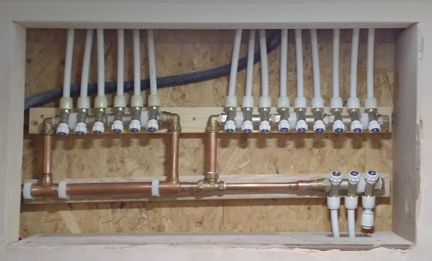
OK, here is the hot manifold also done: Ignore the Hep20 connector to the left; that's just temporary for pressure testing and commissioning. I'll replace this with the draincock later. The TMV fits onto the 28mm common where the 28mm compression endstop is currently fitted. (There is extra insulation behind the panel and I am going to fit a box around this lot for insulation.) However we've got an issue that I would like some advice on. I commented in an earlier post that our flow rate is over 35 ltr / min. This is an understatement. If you do a 6-second flow test with two buckets: the first is to catch the flow for a few secs whilst it settles down, then you cut the second bucket into the flow stream for the six second count, and the measure. The flow rate is ~50 ltr / min. The picture shows the nominal high-flow to the left; low-flow to the right, but the flow out of the "low flow" taps is fearsome -- far too fierce for most of our basins. So we would like to throttle the low flows right back. I don't think that the manifold valves are really designed for such flow throttling. So I was wondering whether to put a restrictor or in or even a 15mm PRV set to 1-bar or so in order to drop the flow rate to the toilets and basins right back. I realise that I'll need to redo the pipe work, e.g. in this hot case put take the flow around to the other end of the low-flow 2×3 manifold set on the right and this will give room for a PRV or a flow restrictor. Comments?
-
"Slight" Increase in Pitch Roof - Planning
TerryE replied to hmpmarketing's topic in Roofing, Tiling & Slating
As I thought, he's gone the full amendment route. A good way to pre-empt any concerns from the planners is to have a word with your neighbour, and get him to write a letter of support which you can include with the application. With a full application, he's going to be consulted anyway, so being proactive will probably go down well. -
"Slight" Increase in Pitch Roof - Planning
TerryE replied to hmpmarketing's topic in Roofing, Tiling & Slating
Yup, I agree with @AliG. I don't think that you'll get way with this as an NMA. Your garage is only 1m from your neighbours boundary, and this amendment will obscure what at the moment is a fairly open sight-line across open gardens and they will lose their view of the setting sun. IMO, the LPA might even treat this as a material amendment. At some point you will need to get your neighbour at No 14 onside. One option might be to trade moving the whole garage to the NE to open up his west facing sight-line to the detriment of his N facing one. I think that you'll need to tread carefully on this one. -
"Slight" Increase in Pitch Roof - Planning
TerryE replied to hmpmarketing's topic in Roofing, Tiling & Slating
The secret here is that if you do have one case officer allocated to your application and keep her or him onside by feeling that you are fully keeping the panning department in the picture and not pulling a fast one then the comfort level is a lot higher and you will get a lot more going through on the nod. -
Will my insulation still work if it is not hard against the blockwork?
TerryE replied to AliG's topic in Heat Insulation
If you are on the case and working the issue with the builder then that's the main thing IMO. I would have though foam filling would be a safer bet than taping, but if you do tape then you'd need to use a decent tape with a 20 year guaranty or whatever. @JSHarris was the trained chemist, so he's probably got a more informed view here. -
"Slight" Increase in Pitch Roof - Planning
TerryE replied to hmpmarketing's topic in Roofing, Tiling & Slating
You are in the lap of the gods because there is no national definition of what constitutes non-materiality. For example we put in an NMA to change the design of our front door (which can't be seen from the public highway). It got rejected because it was a change to the principle elevation. When I pointed out to the planner that my application had explained that the front door wasn't visible from the road, his response was that this didn't matter because callers to the house would notice that the elevation was different to the elevations approved in our application!! So it depends on your LPA but if your garage is in front of the property or this change impacts the site-lines of any neighbours then the planners might still insist on your submitting a minor material amendment. If your LPA allows people to talk to planners the maybe a quick phone call will help resolve the issue, but if they insist on pre-planning advice then perhaps the best route would be just to submit the NMA and talk to the planner once allocated. She or he might then advise you to amend the submission to make it a MMA. (That's assuming that the you can find out who has been allocated as case officer. This is what we planned to do with our NMA, but we only found out the name of the case officer when we received the rejection.) -
Will my insulation still work if it is not hard against the blockwork?
TerryE replied to AliG's topic in Heat Insulation
The main risk with poorly fitting insulation is that there can be a pretty high temperature delta front-to-back and if there are gaps then air convection will start up in the cavity with the air (in your case) rising up between the Celotex and the inner porotherm leaf crossing over the Celotex in the cracks and dropping down the colder gap between the Celotex and the outer porotherm leaf. This circulating air then effectively acts as a heat pump pumping heat around the main insulation layer and reducing its effectiveness. The main way to prevent this type of internal convective circulation is to fix the insulation tight to one surface and to fill any gaps with foam. If the outer leaf hasn't gone up yet, have you though about using something like sticky foam to anchor it back. Might be worth a try. -
Neil, you are correct in the 0.24 U-value is typical of a 120 frame with 100mm PIR in it, but I did also say that you can improve this by using multiple layers. So if you take ProDave's example of one way to do this, he has a 190mm frame, filled with Earthwool and then 100mm Wood fibre board on the outside, achieving a U value of 0.14 which is a good example of what I mean by a composite construction. But note that this is only about 20mm less than my core frame.
-
@Nickfromwales The PCM cells in the SAPVs do contain internal PHEs, but this isn't a conventional PHE with primary and secondary sides. On one side is the phase change material (PCM) and water on the other. There is only one water path and that is the potable DCW to DHW. The 500ml expansion vessel is on this, and the only active device between this and the DHW output is a TMV. I've emailed you the diagram that I referred to.
-
@jamiehamy, ICF is an effective alternative to TF, but considering we passed the 0.6 ACH test first time through without any leak hunting or the like, I am note sure that it is intrinsically more airtight than a properly designed and implemented timber frame. Doesn't ICF rule out using a passive slab type construction because of the ground bearing pressure required?
-
I am using 2×SunAmp PV so no Thermal Store or UVC. Maybe you might consider this (or 1× in your case) as an option?
-
To be honest I don't. As Jeremy says the SunAmps essentially have a couple of Phase-Change Material (PCM) cells that the input DCW flows through to exit through a TMV at a controlled temperature, up to 65°C max. There is a recirculation loop used to pass water through the internal inline heater an the cells, and couple of check valve to ensure that there is no reverse flow to the supply and to prevent this loop acting as a bypass. There's a good figure in the manual which explains this, but since it is copyrighted, I will only include it here with @Andrew Bissell - Sunamp's permission. The small internal expansion vessel is to accommodate in-appliance expansion. External to the Sunamp I have about 1 ltr of water within the copper plumbing to the manifolds and another 4 ltr in the HEP20 DHW pipework. So I need about 30 ml of expansion capacity assuming that we heat everything up, though in reality the figure is closer to 10ml which the HEP2O could accommodate -- ignoring the fact that either of the 2 SunAmp 500ml EVs could also accommodate this. So really the only reason that I would add one would be just in case the BInsp would expect to see one.
-
Tony's build (@tonyshouse) has demonstrated that you can achieve passive-class performance with a block/brick cavity wall construction, but it's a challenge. As I've said elsewhere I feel that the root issue is total failure of innovation and true quality control in the major builders. If you look at so many other sectors of business technology and innovation over the last 30 years have totally transformed how the products are mode and the services are delivered. IMO, the building industry as a whole seems to have systemically resisted attempt and change and both the government and related professional bodies such as RIBA have miserably failed to perform their roles in legislating / advocating such change. So we are left with a few small builders and specialist firms, and self-builders showing by example. @Sensus used the phrase anally retentive when discussing another post and Jan often refers to me as being anal to describe to sort of fine attention to detail that I sometimes adopt. Yet we don't talk about Rolls-Royce being anally retentive about the design and manufacture of their jet engines or Apple being anal about the design of their iPhones, etc.. It seems to be almost a presumption that whilst attention to detail is essential (and expected) in some business areas, when it comes to building a house then this is just over-the-top. However, I disagree. Quite a few of the active members of this forum have demonstrated by personal example that you can build a top-quality passive-class home for the same sort of price as your average mediocre new-build of the same footprint, etc. Where there are price premiums these are more to do with the overheads of building one-off rather building a high quality product. But the devil is in the detail, and maintaining that quality, so maybe we should just use the "anal" description as a badge of recommendation. If you are a self-builder who wants a highly efficient, high quality, low maintenance to live in then you need to get a bit of anality yourself or find a professional architect or project manager that you trust to do this for you.
-
I think that my main design axiom is Keep it Simple Stupid (KISS) wherever possible, instrument and add the complexity only when needed. In this case, I think that I should allow for the retrospective fitting (if necessary) of something like the 100ltr Zimlet, which is 450mm diameter and 960mm tall in its vertical config. I know the SunAmps have an internal Expansion vessel, but I am going to have to do the sums and include another small one for the system as a whole. This will be essential if I don't have the Accumulator from day 1. Thanks again guys.
-
When I cranked the system up to 7 bar for the pressure test, I bent the lever on the 4 bar pressure gauge so it now reads ½bar at zero -- oops!! But to the next sup-topic: Accumulators -- do we need one and how big? It's pretty flat where we live, so our mains is pump-assisted off a small staging reservoir in the forest about 1½km away. It comes into the house at 3-bar static pressure. There's an iron water main in the road fitted with a 28mm MDPE spur to our the stopcock/meter on the pavement (I watched the guys do it), and then a ~10m leg of 25mm MDPE across our front garden into the house and our mains stopcock. From there it will be 28 / 22mm piping to the manifolds. I've just done a quick 6 sec flow-rate test and the flow-rate through my home-brew pressure test kit is fearsome -- over 35 ltr / min. OK, the PRV will knock off maybe 0.2 bar, but this flow rate is more than enough to supply two showers in parallel. So now I am asking myself do I really need an accumulator and if so how big? I really can't see the point in having a large one. Thoughts and advice please experts?
-
(Content removed after objection by MrsTE) John should have been the target anyway.
-
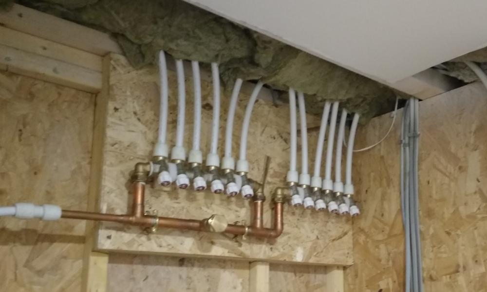
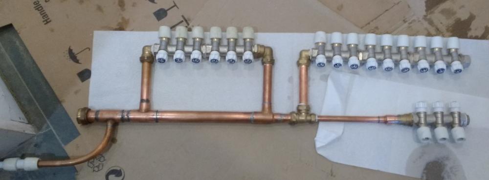
A quick update. I've added a wet 0-6 bar gauge to my home-brew pressure test setup and connected up my DCW manifold and cranked it up to 7 bar. One advantage of breaking your system down into separate subsystems if that you can assemble each on the bench and test properly before installing in place. To be honest I had a 28mm dry joint so its lucky that we did this. The problem was that the end of the 28 pipe had a shallow ding in it that I hadn't noticed -- goodness knows why -- but the result was that the end feed solder had a dry bridge, and this caused a joint failure that I needed to redo before the 7 bar test worked. The main fill will be where the 28mm endstop is to the left and the 15mm below will ultimately have a draincock on it, but it is currently a pressure test point. And this is the manifold in position. Not quite as neat as Nick, but it will do Compare this to the photos on the original post. I blame Jan for it being slightly crooked.

-
@NSS, Neil, you can definitely get a single wall construction up to the same standard as a twinwall in terms of U-value, typically by adding extra layers of insulation such as a plasterboard/RUR composite over the service cavity. I haven't done the numbers but a 50mm PUR or PIR layer would help a lot. The quality issue is still problematic particularly if the inner skin has been incorporated in the factory. At least if this is done on site, the home owner or project manager can inspect the fit of the internal block insulation and where necessary use injected foam to close up fitting gaps. (A gap of 5mm top and bottom can more than double the effective U-value.) As to the DDF, this is more down to the bulk properties of the main fill material. PUR and PIR have excellent the thermal conductivity, but also very low the heat capacity, and its the ratio that largely dictates the DD. Any wall which uses these as its main filler (or any other low thermal capacity insulation) will usually end up with a low DD. See this article which describes the concept and issue: Greenspec: Decrement delay & Thermal buffering.
-
Thanks for bringing us back to the subject. In your original post, you said that you were considering two methods of wall construction both timber frame both with external timber cladding: the single and double stud wall constructions. The double stud wall construction technical, usually using a Larsen Strut design has only come into popular use after BRE 433 was first developed and even the 2006 edition which is the one that I have doesn't even discuss it. So what this boils down to is do you want a number to plug into a SAP calculation to keep your building inspector happy in which case take the advice that Martin (@Sensus) and Ian (@ADLIan) gave and go with that. However, Jeremy and I made the assumption from your OP that you actually want to understand the difference between the benefits of the "double stud wall" construction. Perhaps addressing your original Q was a mistake on our part. But at a high level, my summary is that: A single wall construction will typically have a U value of ~ 0.25 and a decrement delay factor of <3 hrs. You are also critically dependent on quality control during manufacture since poorly fitted insulation will allow air circulation within the panels with a severe degrading of the actual U-value achieved. There is a some risk of material cold bridging in the frame A Larsen strut construction will typically have a U-value of ~0.12 and if filled with blown cellolisic filler have a decrement delay factor of much > 24hrs. The blown filling technique is far less prone to voids and consequential bridging. The first approach will give you a warm house that you will still need to heat with a conventional central heating system on all floors. The latter (if you get the other system components right) will give you a house that you will only need to heat a couple of months a year and will essentially act as a single zone, so no central heating system is really needed, though you do need some method adding say up to 1 kW during the mid-winter months. Jeremy and I both have a twinwall house so we are talking personally about our experiences. Martin is professionally an architect, Ian is a SAP assessor. Perhaps they can use their expertise also to address your original Q from their perspectives: what are the pros and cons of single wall vs twinwall construction?
-
The potential issue as I see it with slow withdrawal is that the foam goes pretty firm within an hour or so, but can carry on expanding for up to 12 hrs, so the deep expansion can create a lot of internal pressures leading to bulging. This is why I suggested a similar method working from the centre out, but doing it in multiple fills so that each fill is no more than a few inches, which expands out to around 6 or so. When I fitted my MDF cills I CT1'd them onto fixing battens, then after the CT1 had gone off, I used your withdrawal method to lay back-to-front lines of foam in the voids between the battens on a foam-to-gap ratio of roughly 1:2 and left this to go off. The foam then expanded to pretty much fill the under cill void. I then went back the next day and did any infill needed and this time I got some overflow. This I cut off another day later when it was truly hardened and the cills as solid as a rock.