TerryE
-
Posts
3822 -
Joined
-
Last visited
-
Days Won
30
Everything posted by TerryE
-
We might have the same problem but in our case mitigated the worst of the symptoms by an unintended consequence of an earlier design decision: we originally had 4×90m loops but I asked MBC to remove the areas under the units and breakfast bar from the cover. At this point it was just easier to drop to 3×100m so we also dropped the utility room -- except the feeder runs into the manifold which all run into it. But I was also thinking of doing a plate model were I approximate the slab by say 500×500 tiles with a plate heater at 40mm below the surface and (1) treat the UFH circulation as a very high horizontal cp on plates where the UFH is routed and (ii) include the deeper ring beam areas, again with an increased cp to reflect the overall effect of the rebar. But this is a lower priority at the mo. Jeremy, if you want to remove the buffer tank then you need to trim your other control mechanisms: (i) I recall that @jack runs without a buffer and sets his ASHP output temperature down to around 25°C at which point it is outputing around 2kW (this will depend on the low rate), and (i) you may need to open the UFH TMV mixer threshold slightly, because it's the limits on the Δt that in turn limits total amount of heat that you can dump into the slab in one go. At the moment I am planning on a single dump during E7 low tariff period because I am using an inline heater, however if I was using an ASHP then it might be better to use smaller heat slabs 2 or 3 times a day, say equating to the ASHP running for 30-60mins. More modelling
-
What would be really useful for people like @joe90, @jamiehamy and me would be to some of those that have been through this such as @jack, @Calvinmiddle, @JSHarris, @PeterW, @PeterStarck just list off their feed stack in terms of components used that is from the MDPE coming in to the split of feeds to DHW and DCW, plus maybe any comments on any retrospective +/-s. And not forgetting the pros here like @Nickfromwales
-
As I said in another post if I compare our 20-30 year-old plumbing in our current house and the HEP2O manifold system in our new house, they are truly a generation apart in terms of technology. It's not just the materials, but the skills needed to do the latter are fundamentally different to the former. The old system was unpressurised, all in copper and loop-based so lots of solder joints in inaccessible places. The only active components were manually operated taps. In general this was very energy wasteful. The new system is plastic / push fit radial so no joints within the building fabric; the system runs at a limited mains pressure and there are sensitive active components. A large amount of thought and planning has gone into achieving the overall energy efficiency. The old system was a trade and the new a technology that requires a professional approach and a lot of the old trade skills are simply redundant. Yet I suspect a large number of plumbers (probably a significant majority, IMO) have yet to make this switch, so the consumer or self-builder might be very constrained by the skill set of his chosen plumber. A friend of mine doing his own new-build is in exactly this situation: "old-school" plumber = old-school installation = expensive and energy inefficient. In our case we can easily supply most of the skills and labour needed. And in a lot of area such as layout planning, scheduling with other trades, component procurement we're probably a lot more skilled than the average plumber. What we really need is a few days for high-grade professional services: to do the component selection for the active components and to review our design, and then at the back end to commission and test the completed system. I'd happily pay double the going plumbers day-rate to get this sort of quality service, but it would only be for a few days so it would still make economic sense for us. But for the true professional plumber, this is a very niche market.
-
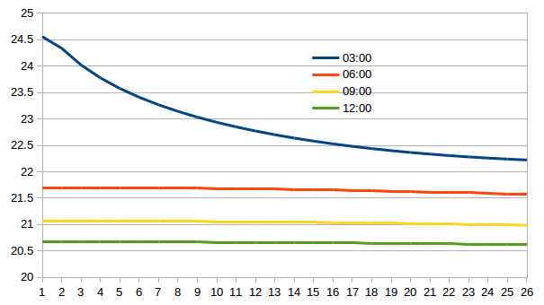
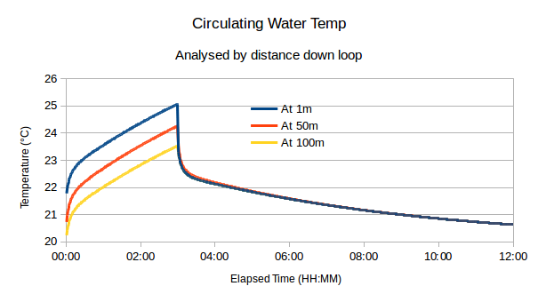
Replies to Qs The GNU gfortran compile is part of the GNU gcc bundle so adding it takes seconds on a Linux (or Cygwin if you run Windows) if you haven't already got it installed. It is Fortran90 and I use the F90 features, so it is a little different from the old F77 that we both used last time in anger. I initially wrote the early versions in C but the C language just gets in the way of reading the code and understanding what is going on. So I moved it over to Fortran as this sort of application fits it so well. So I prefer this. As to the GUI approach, all of the parameters are just that, a block of Fortran parameter declarations (one of the F90 additions and which the compiler treats as compile-time including things like real,parameter::pi = 2*acos(0.0) which is nice). If I want to change anything, just tweak the parameter block, save and recompile; it only takes a couple of seconds. So no fancy input parsing; I leave this to the compiler. As to the output I simply dump CSV data to stdout, and post process this with (LibreOffice) Calc. for example my main output code is: write(fmt2,'(A,I4,A,I4,A)') '(I5,1H,,I5,',2*nRings+2,'(1H,,F8.4),1H,,F12.4)' do i=1, nSections write(unit=*,fmt=fmt2)iter,i,Twater(i),(T(i,j),j=1,nRings),(W(i,j),j=1,nRings),Wair,Q(i) end do (The first line is standard hack because you still can't provide a variable count in a format repeat group.) Sometimes I might use a shell filter such as grep -P '^\s*\d*,\s*50,' /tmp/a.lst > /tmp/a1.lst as a post process. (This picks out all lines with the second field = 50, that is the midpoint in the 100m loop), to keep the Calc file smaller. If such a filter is useful, then it's trivial to add it to the code as an extra line or two of logic. Nick I'll cover this in my extended discussion below. Basis of the model (This section can be skipped by normal mortals, but this in the Boffins sub-forum after all.) My passive slab has ~73m² of concrete 0.1m thick – that is roughly 17½ tonne of concrete in total across the footprint of the house, but the slab also contains another 10 tonne of perimeter beams, cross bracing and steel beneath this which all adds to its overall thermal capacity. Some 55 m² of this is covered by Under Floor Heating (UFH) pipe placed roughly 50 mm below the slab surface in 3 loops, each just under 100m in length and laid in the standard “double back” spirals used in most UFH designs. There is 300mm EPS below and to the sides of the bulk of the slab, so the main (radiant) losses are into the living space above it. Accurately modelling this type of design is practically impossible because of the uncertainties introduced by the steelwork within the slab, and of huge computational cost of executing a time-varying 3D spacial model. So what I wanted to do here was to focus on the time dynamic and heat propagation effects around the pipe run themselves, by modelling an approximation which is more easily simulated but which will have the same macro characteristics of the heat flow through a real concrete slab. So what I am going to focus on in this model is an approximation which is a 100m long homogeneous tube of concrete some 150mm in diameter with a hole running through the middle some 14mm in diameter. Water is circulating through the centre hole at 1 m/s and is heated by a 1kW heater at one end. The surface of the concrete tube is radiating heat into a black body at 20°C at 3.5W/Km². The initial temperature of the concrete is 20°C. My reason for choosing this radially symmetric geometry is a pragmatic one: that this type is it is radially symmetric and therefore computationally solvable with a 2-D approximation, (and its steady state can by analysed analytically). The 3 × 100m pipe runs have a total volume of 5.3m³ which is pretty much the same as the piece of the slab covered by UFH (albeit roughly half of the total mass). The total surface area of the 3 tubes is 141m², which is roughly double the radiating area of the slab, so halving the normal approximation of 7W/Km² will give a similar net heating effect as the actual slab. The 1kW × 3 tube arrangement is directly comparable to the 3kW inline heater that I plan to use initially. So overall this model is good enough to explore some of the issues and performance characteristics that I want to quantify. I approximate the concrete mediums by a set of concentric rings at a uniform mesh interval. As previously mentioned, since the radial temperature gradient is nearly 3 orders greater than the axial gradient in practice I can practically ignore the cell heat flows though the concrete and assume that the only axial heat flow as as a result of the circulating water. Removing these terms also allows me to increase the ∆l (intervals along the pipe) whilst keeping the evaluation stable. By assuming that each material layer is a fixed multiple a fixed thickness ∆xi and by using a fixed time step ∆t, the solution can be approximated on a fixed (∆x, ∆l) mesh using a n∆l × 1-D implementation of a formulation of a simple delta approximation to the 1-D heat equation. This formulation uses 2 material properties that are specific to each material in the wall: VHC the (per) Volume Heat Capacity, which is just a product of the density ρ and the heat capacity cp K the thermal conductivity It also is expressed in terms of the heat flow, W, at each layer boundary and of the temperature at the centre of each layer, so for the jth section of concrete pipe, Tij is taken at midpoint between boundaries i and i+1 and conversely Wij is calculated on the layer boundaries between temperatures Ti-1 j and Tij. Note that a positive W indicates a left→right heat flow (that is T is decreasing in the direction of increasing i). The basic equations internal to a given layer are straightforward and documented in the source code. I've left discussion of the heat equation itself to Wikipedia, etc. Analysis of the Results and What This Tells Me This modelling the slab as three pipes of concrete has some strengths and some serious limitations. The main advantage is that this gives us some understanding how the slab reacts to a prolonged heating period followed by the heat source removal. What it is missing is that this radial approximation will start to break down as the heat diffuses through the slab, and in particular in my slab where I have large internal and perimeter ring beams which add another 70% thermal capacity of the slab and I'll return to this point later. When the 1kW heat is applied it takes a few minutes for the return to start to lift in temp because the slab is cold and sucking all of the excess heat out but over the first 15mins or so it then settles down to a quasi steady state where the 1 kW generates a lift in circulating temp by some 1.6°C so there is a steady thermal gradient of roughly 0.016°/m along the pipe. The radial profiles then slowly rise and the whole temperate slowly increases to support pumping 1Kw/100 = 10W per metre into the concrete. The temperature profile of an individual 1m segment looks very much like the analytic solution to the radially symmetric 1-D heat equation because the second order terms are so small. (I've updated the first graph above to show the temperature profile of the water over time for the start, middle and end of the pipe, and which shows this.) The ambient air temperature plugs into the outer boundary condition. The external heat loss is represented by a radiance of 3.5W/Km² at whatever the external Δt is. This is a bit of botch because the real value is nearer 7 but only half the area is exposed, so this gives the right ballpark for the BC. As soon as the heat is removed, the slab rapidly transitions into a different mode. Since the radial profile is no longer being pumped from the centre, the 1/log(r) type profile starts to relax back to a more uniform profile as the heat start to spread more uniformly through the pipe cross-section. The circulating water now acts to redistribute the heat created by the 1.6° gradient pretty uniformly along the concrete "pipe" and another hour or so the difference along the pipe is minimal. It is really by this point, say 5 hrs, in that the radial approximation begins to lose its validity. The slab is acting far more as a uniform plate some 75mm thick, insulated below and radiating above. In my case the heat energy will also started to get "cached" in the beam underworks partly assisted by the rebar acting as heat pipes. So whilst the general shape of this curve will remain the same, I think that my real slab will be more sluggish in dumping heat so the curve will be flatter. My Conclusions You can use the slab as a buffer If you want to pump 3 kW into the slab then you need to accept that the circulating water temperature will rise of its own accord maybe 5-7°C more than ambient. Alternatively if you limit the Δt a few degrees than the rate at which you an pump heat into the slab will be limited accordingly. Measuring the flow return temperature is the easiest way to instrument the overall temperature of the slab (so llong as you ignore any heating periods and for maybe 3 hours after any heat input.
-
Dual Hobs in Worktop, design vs structural engineering
TerryE replied to TerryE's topic in Kitchen Units & Worktops
In a previous post you mentioned that you were hankering for a handle-less look. With a plain handled door style you could fairly easily swap out the door for a different colour in the same or visually similar style and transfer the handles to maintain the consistency. The disadvantage of a handle-less look is thaat the handle is sculptured into the door profile and is part of the door itself. Companies temp to redo their styles every 5 years or so, so there's no guarantee that you will be able to source doors with the same handle profile. Just a thought to factor into your design choices We are only a couple of hours down the M1 off J15 , so if you and Ian are heading down the M1 south, why not arrange to pop in and look at what we've done. -
Spoiler alert: I have at last got my head around all this through a mix of simple analytic models and a simple 2D model of the slab. I wrote the model in Fortran to appeal to the other old farts that might just want to look at it or have a play. IMO, the bottom line is that using a buffer tank for a low-temperature UFH is entirely optional, though the controls and heating strategy are slightly different with and without. If you already have a buffer tank then it's not worth redoing the system, but if you are about to install one then IMO you can leave it out. (Note this primarily applies to an MBC / passive slab or equivalent house.) I've got friends coming around for a drink in 15 mins, so I will have to write this up later. But I'll dump a couple of graphs here for food for thought. The model outputs are entirely consistent with my analytic approximation. I will explain more when I next post. Until later ... (drinky time)
-
Well, that was a useful Q to ask, as the answer caught me by surprise. I don't suppose anyone knows one that they would recommend?
-
Gosh, isn't filtering the water supply a little extreme? I've managed 60-odd years without this. I've seen scale inhibitors installed. How common is this?
-
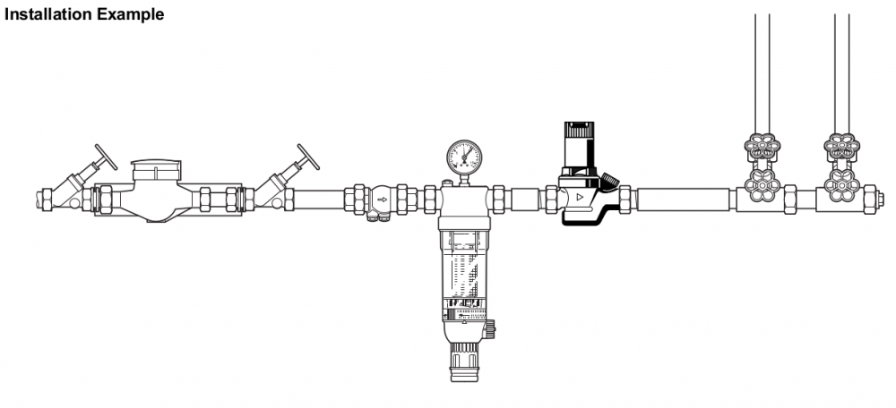
Just as quick Q, I came across this example in the Honeywell Pressure Reduction Valve (PRV) spec. I get the meter with isolation valves either side, the double check valve, the pressure gauge, the PRV anf the two main circuits to the right, but what is the device under the gauge? A scale inhibitor? Or any better guesses?
-
I've been looking into the options for meters and valves. These Solenoid valve WRAS approved 2/2 way Normally Closed 1/2"BSP are £56.41 ea. and I can live with the 100% mark up compared to JSHs suggestion for the WRAS label . The metering is more of an issue. I can get WRAS approved meters either with M-BUS or simple pulsed output. M-BUS is a PITA, but my main concern is that these are really for billing-type applications where you want confidence in total flow rates. But they can also cause around 0.2 bar head loss which is less acceptable. I might just slip in one of Neil's suggested Hall-effect flow meters which is really what I want anyway. If I do use this type of meter then I will have to have some manual bypass for at least one of the SunAmps so that I can at least draw hot water if there's been a power failure.
-
If you use the SunAmp inbuilt mixers then the full flow goes through the 15mm tails. By setting them to max, or 65°C say, then using the external mixers I will do a ~2:1 blend in the mixer with the DCW and so be able to sustain a higher flow. I also have 2 SunAmps in parallel and using the external mixer simplifies setup: only one TMV to trim. Anyway, that's my thinking, but we'll have to see in practice.
-
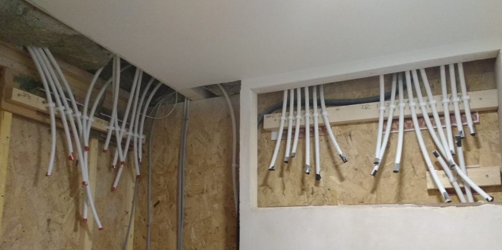
Nick swears by HEP2O. As to the layout, the basic rule if you use a manifold system is no buried joins if at all possible, and one (H +) C to one appliance. Our exceptions to this rule are: We have some elbows in the studding where the pipe is coming down the wall and needs to do a sharp 90° (e.g. the shower tails) We have the cold feed dishwasher T'ed off the kitchen sink cold. We have the cold feed washing machine T'ed off the utlity sink cold. IMO, laying out the pipe approaches to the manifolds is a bit like laying out a circuit board: it can get busy and messy and you need to avoid getting pipework in knots. Do your foulwater first because those are fat and difficult to route. Then the plumbing, then the electrics. I reserved the roof space in the GFL toilet adjacent to my manifolds for my "Clapham Junction" and actually did a full routing diagram for this before I laid a single pipe, and I had to go through three design iterations to get everything in the right order. Jan though I was being totally anal and going overboard -- until we started pulling the pipes and then she did a volte-face and agreed that it was a bloody good idea. Remember to space out the hot and cold manifolds to give yourself routing room. I am using 2×SunAmp instead of a TS or UVC. They immediately below the hot manifold so my hot copper runs total about 2m of pipework. That's it. Read through the various worked descriptions on the forum.
-
@jamiehamy, Have a look at the thread I've got running at the moment. We are doing ours in HEP2O using a manifold system as well. Deciding the runs and placing the manifolds is the bit that needs careful planning. We did all of ours in 15mm because our layout means that nearly all of the runs to the manifold were pretty short so standardising on one bore simplified it all. Though I admit using up a coil of 10mm for the low flow toilets and hand basins is something that we could have considered. I would question the need to use 22mm to the bath in a pressurised system. Unless you've a got ridiculously long run then 15mm will be fine, and avoid needing to use buried bends or joints.
-
@Nickfromwales, when I get rid of this sodding man-cold that Jan's mate -- well really our mate -- gave me, I'll be starting to pressure test our system, so I will -- for the first time -- have a quantitative measure of our mains pressure, but from the subjective thumb-on-faucet test, I reckon that it's above 2 bar and below 3 -- but I might be wrong. I'm a sceptic by nature which means that hard empirical data that I trust wins out over beliefs every day. However unlike May, Trump and those other wankers, if I don't trust the data then I double check it rather that ignoring or simply rejecting it. And you might have noticed that my preferred medicine for man-cold is legally distilled and purchasable. Ho hum. Sorry other readers. Thanks to the back story on our house, we have got 1×toilet, 3×wetroom en-suites, and 1× bathroom -- in a house that will have 3 relatively dirty occupants 95% of the time (that is we bathe or shower less than once a day on average). Given that I once had 3 sweaty teenagers in our current farmhouse with its tank-fed indirect system, our new house will have at least 2× the supply capacity with 60% the demand, so I really don't envisage any issues in practice. Over the last 6 years (when there's only been 3 occupants in the farmhouse) we have averaged about 270 ltr / day mains water draw-off for all three of us, so I don't see the need for huge accumulators, even if the mains pressure proves crap. My current thinking is that we do have a DCW accumulator, so that we don't have feed issues if we do have a couple of showers going at the same time, but something relatively small -- say a 70ltr accumulator -- which should carry us over the two shower hump. However, I will order the TMW(s). Ta muchly. Mrs E doesn't think that we need a separate drop-down for the low flow basins, but she's far more likely to value your views on this than mine, so post away with your pearls of wisdom. PS. Do you ever drive over the eastern border? If you ever have to go up the M1, there's a very cheap hostelry just off J15 (This offer is also open to other selected members).
-
So what is the current wisdom on TMVs? I am talking specifically about the mix-down of the ~ 55°C output from the SunAmp with room temp or colder Domestic Cold Water (DCW) to feed the DHW manifolds. Have you guys got any personal recommendations? Is 22 or 28 best here? The 28mm TMVs seem to cost crazy money. I've got 2 × 15 outputs from the SPV into 22 and the DCW into 22. The TMV output splits again into 2×22 a few cm after the TMV output. Our current house DHW is in a mix of 22 and 15mm copper which an internal cold header tank so is at ~ 0.2 bar and we've never had any problems. Is it worth a separate 15 or 22 TMV for the low flow hand-basins set at a non-scalding temp, say 48°C?
-
Dual Hobs in Worktop, design vs structural engineering
TerryE replied to TerryE's topic in Kitchen Units & Worktops
In 5 years time you might be saying "Oh, that's just so 2010s" and cringe. I think Ian would have apoplexy if you wanted to redo the kitchen in anything less than 10 years at that price -
Why not just an accelerometer to detect the vibration / hum whilst running. Then you don't need to touch the mains voltage.
-
It's not good for your or your neighbours lungs either!!
-
Neil, that's brilliant. I am not looking for absolute total flow accuracy but flow rate that I can measure with an IoT device. This fits the bill exactly. I think that this level of instrumentation and automation is fast becoming a post go-live system upgrade. @JSHarris Jeremy. Thanks. Just what I was looking for. Much appreciate both your inputs.
-
You make a valid point This depends on the UFH flow rates. At a flow rate of 1 m/sec the UFH manifold will be circulating just under 30l/min. A full on shower might be half of this, so just doing the thermal balance at a 5°C to 21°C exchange, this would boost the supply to around 15°C. As you say nowhere near as good as 21°C but still worth having. Of course the efficiency would fall a lot if there were multiple demands, but this isn't a frequent pattern in our house and a lot of use: hand-basins, sinks, etc., are a lot less than 15l / min. And as I will discuss in a later post, there are times such as in the morning when the UFH loop will pull well over 25°C. This PHE might also be a post inspection update It really depends on the price of the PHE to see if doing this is worthwhile. @JSHarris Jeremy, what did you buy and how much did it cost? Another piss-ball is that the pulsed water meters typically generate one pulse per 10 litres which isn't really fine enough for what I want. Maybe I need a bit on LED sensor magic over on the face of the meter to directly read the little wheel which goes around once per litre.
-
@PeterW Peter, on-off is really what I want here. The two SunAmps are in parallel, mainly for capacity, but to a lesser extent for flow rate. What I am a little concerned about it balancing them, not so much in terms of max flow rate but in draw-down Joules. Maybe 95% of the time one SunAmp will happily feed the flow demand so my idea is that I always have at least one open (and normally only one, so that I don't get external heat losses from the other). I track the flow through it and the ∆T, so I can calculate the Joules draw down from it. I'll swap over once or a few times a day so that I roughly balance the use. Where we may need both open at once is on the very occasional time that 2+ showers / bath are going at the same time, and in which case I open both valves, and I assume a 50:50 split for draw down of Joules. I don't have photovoltaics (PV) so I only want to recharge them using E7 low tariff whenever practical. However, I also want to know (again less than once in a blue moon) when I am getting close to daily capacity and and here I will take the high-tariff hit for the convenience of not running out of hot water. @JSHarris Jeremy, I will come to the UFH on a post in a few days, but my issue here is that I am switching what the BRegs class as potable water, and I am putting this in before the B Inspector's final audit. So I need to show on my commissioning checklist and Bill of Materials (BOM) that all components have WRAS approval for potable water. He'll almost certainly not check, but he might because the setup is very different from routine and he might just be very interested in what I've done, and that's the rub. Of course the other option is to fit the valves post sign-off, but either way, I'll be occupant. Why the current BRegs stipulate that the hot supply must be potable seems strange to me, but they do . Maybe people like to gargle in the shower
-
So my specific Qs are: Any recommendations for the TMW, the 2 × electrically controlled shut -off valves and the digital / pulsed water meter, bearing in mind that these need WRAS approval for use on domestic cold potable water. I've got a box some 30×15×60 with all of my hot stuff in it that needs lagging. Any recommendations here? I was thinking of using that Aluminium covered quilting. Beg, beg
-
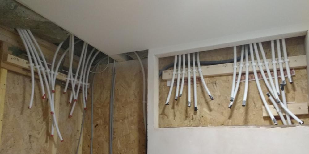
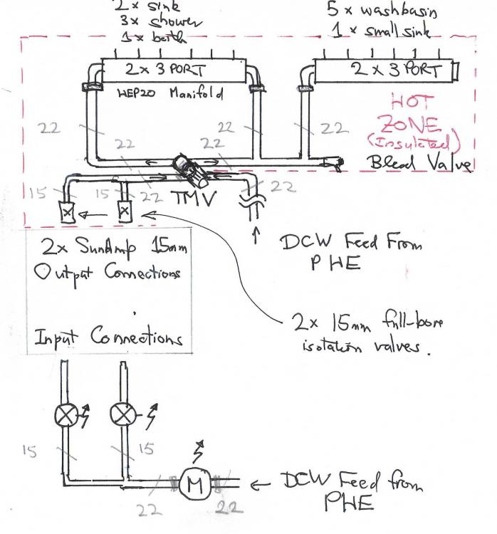
I am not sure whether this is best done as a blog post or a discussion thread, but since I am as much canvassing feedback and comment, I will start this as a thread and maybe summarise later in a blog post. I want tell a quick story as an introductory analogy. Back around the early 1980s when real computers took up most of a room, "Mini computers" were only the size of filing cabinet and ran at 1 MIP or thereabouts, and the first 5MHz IBM PC had only just been introduced, I remember reading a "futures" paper that took Moore's Law and extrapolated it into the future. What it concluded was that 1 GHz computers would be quite possible in the future, but identified that sticking point would be the memory: because of the speed of light, it would have to be less than 6" away from the processor! Unbelievable. Except that's how all processor boards are laid out today: memory on-chip or right next to it. My current house was designed around the time this paper was published: lots of copper piping and loops, the boiler on one wall, the hot tank 4m away in a cupboard, the kitchen 8m away again in the other direction. So the copper is in a mix of 28, 22 and 15 to get the flow rates -- and lots of copper to heat up on the way to the kitchen taps. Old mind-set. OK, plumbing technology hasn't changed nearly as much as computing, but a lot has changed, though many plumbers still hang onto techniques that were good practice 30-odd years ago. What I've tried to do in this new house is to abandon unnecessary concepts and optimise the system as much as possible for the use we want to put it to. So one core aspect is that we've already planned the house to centralise the wet works as much as practical: the house layout is roughly 3 × 2 tiles on two stories and a 3 × 1 in the warm roof. It is double fronted with living, dining and sleeping to the left and right. The front centre is a hall and landing column giving access to all rooms, and the rear centre contains the groundfloor (GFL) toilet, utility, bathroom, and one en-suite. Another en-suite backs onto it. We're using a HEP2O manifold system, so this means that all of the pipe runs are short, except the 7m run to the kitchen taps and a 6m run to the en-suite in the loft. The only long run of low-flow hot is to the loft en-suite hand basin, so we've just kept it simple and used 15mm HEP2O everywhere. What I want to talk about first in this post is our domestic hot water (DHW) system. It is heavily influenced by a thread where we discussed HEP2O manifold options with @Nickfromwales and others, and the example that he posted on this thread (with my current tails along side for comparison): This second photo is of my GFL toilet. The cold manifolds will be on the right (the two groups are high flow and low flow respectively) in a boxed in section above the Gerberit and the hot ones on the left in what will be the services area some 1.4m wide × 0.65m deep that will house all of our under floorheating (UFH) and waterworks and be separated from the toilet area itself by removable quick release panels. Some of my design drivers / rules are: All of the pipework in the service cupboard will be in copper, and sized 15 / 22 / 28 according to flow rates. My preferred approach is to use end-feed copper joints / fittings except where functional fittings are compression. This being said, I also use occasional compression joins to allow me to make up any soldered sub-assemblies on the bench, so that I don't have to solder in place. The hot runs have been reduced in size to the absolute minimum to avoid waste heating. I am using 2 × SunAmpPV (SAPV) for my DWH heat store. I am metering water flows and temperatures. I am preheating the cold feed for DHW to ~21°C using a plate heat exchanger (PHE) coupled to the UFH slab loops. So I have the 2 × SAPVs each using the supplied 15mm tails to a common 22mm @ ~55°C that is mixed with a 22mm @ ~21°C and fed directly into the DHW manifolds. The SAPVs are on a platform in the cupboard to keep this hot line short and to provide space underneath for the UFH subsystem. Each SAPV has a electronic value on its input feed, so that only one is normally connected in flow. Above a threshold flow rate, the second valve is opened to allow parallel flow from both; the "on-stream" and standby SAPVs are swapped during the day to balance the heat drawn down from the units. The PHE merits some explanation. In the winter our cold supply is typically at 5-7°C mixed which is the boosted to 48°C for supply to the hot taps. So that's a delta of 42°C, say. By using the slab to preheat the cold supply to ~21°C this drops the delta that's drawn from the SAPVs to 27°C and this effectively increases the supply capacity of the SAPVs by just over 50%. This is isn't free of course, because I will still need to add this extra heat to the slab on heating days, but we still effectively get 3 SAPVs capacity for the price of 2, and our maximum hot flow rate is prorated accordingly. On the thermal feed side, the PHE is (always) serially connected in the UFH circuit behind the return UFH manifold. The H/W flow rate is used to create a demand that will override the UFH circulation pump to the on mode. The intelligent charging and 1 / 2 use of the SPVs requires my Home Automation system to collect flow rate and temperature info from these feeds. My original plan was to put the digital meter and electronic valves on the hot output side of the SAPVs, until I had that "Durrrhhh" moment and realised that I could just as easily meter the input cold side. So here is the proposed schematic for my DHW. I have still to select the Digital / pulsed water meter, the valves and the Thermostatic Mixer Valve (TMV). But any personal recommendations / comments will be appreciated. The hot zone (that is pipework over ambient temp, and which must be lagged) comprises the 2 × 6 port manifolds, the TMV, some 1m of 22mm pipe and 1m of 15mm pipe a couple of full bore 15 mm isolation valves and the two flexible couplers to the SAPVs. Arguably, I should do the common section on the output of the TMV in 28mm, but given that its about 5cm long, there doesn't seem a lot of point. I haven't shown the SAPVs because they are just white boxes with some connectors at the back, that the flexible 15mm tails connect to. What I've missed off this diagram is the four temperature sensors: one on the combined input to the SAPVs, one on the combined hot O/P into the TMV and two one each of the output tails from the SAPVs.
-
Or just get one that doesn't have the glass in the first place. I think that Jøtul still do these.
-
The height is a trade-off: bending the back all of the time or lifting wood. I personally prefer using my legs to lift and keeping my back straight when I cut. As to the notch, IMO you should engage the dog teeth and then let the saw's own weight and its own pull rotate it into the log. No need to push, pull or force the blade down; if you are doing this then your technique is wrong. This being the case, the notch only needs to be half (maybe up to the full) maximum width that you want to cut. And keep your blade sharp. As I said before the files are cheap and YouTube gives you lessons on technique. If you do start hitting nails then it's probably eaiser just to order a new chain. They only cost ~£15, IIRC