


TerryE
-
Posts
3822 -
Joined
-
Last visited
-
Days Won
30
Everything posted by TerryE
-
Rob, can I just emphasise a fundamental characteristic of at least our PH. Nothing happens quickly. If you stopped heating it in winter it would only drop about 1°C/day at most and heating it up again is pretty sluggish as well, so its just far easier to keep the whole house at the same temperature all of the time. The one caveat here is if you've allowed your architect to persuade you to have "acres of glass" especially south facing, because a serious dose of solar gain can turn a PH into a greenhouse in hours. The other thing is the lack of zones controls, radiators on various walls etc. The rooms are simple and clean and the walls are for hanging pictures, bookcases and putting furniture against.
-
One of these days I will have time to write all of this up but my major post-build hobby is acting as the lead developer for an IoT firmware: I am upgrading the firmware to a Lua 5.3 version and fighting getting a £2 chip to run 15K lines of dense test vectors ?
-
No kit at all. I have a couple of DS18B20s in the wall fabric to get the average house and the external temperature forecast is a NodeRED HTTP request to datapoint.metoffice.gov.uk. This goes into a NodeRED function node (~60 lines of Javascript). The estimator has two linear terms with coefficients starting on my modelling of the house performance but then adjusted base on a fit of historic data. My HA system is an RPi + SSD, total cost ~£70. All the data logging and relay control is done through ESP8266s, total cost maybe £20. The most expensive bit were the 16A SSRs used to switch the Willis and SunAmps at around £45 each IIRC. Sure, but why don't you start the ball rolling just @ me so I pick it up ?
-
We've got one towel rail in our master bedroom ensuite and TBH we don't use it. It is really hard to really understand what it is like living in a PH unless you do so, because the experience is so counter-intuitive to all of your pre-PH experience. The whole fabric of the house is within ±½°C or so of the mean, and even if you are topping the heat up overnight there is still maybe about ±½°C ripple on this at most. There aren't cold spots; there aren't cold periods. I've got UFH in my slab, and nothing else (other than that towel rail). My HA system does some sums each night and calculates the kWh input needed for the following day as a simple function of the average forecast temp for the following day and the delta between the target set point (we have ours as 22.4°C) and the overage over the day. So let's say it calculates this as 12 kWh, then the Willis is turned on from 03:00-07:00 so that we use E7. That's it. I do have a few tweak that I want to do: when we have visitors then we should really offset the heat demand for the extra heat from their bodies, but we don't so the air temperature will heat up a degree or so because of the extra walking radiators, but this rapidly goes back to normal when thy leave as the fabric temperature doesn't really move. I also "cheat" by having a small oil radiator on a Sonoff timer in Dec/Jan when I need more than 7 × 3 kWh heat, so I use the rad to add extra space head during the E7 window. It is all really simple: if your house loses X kWr/day at your target environment temperature and with the current outside temperatures, then if you put X kWh heat into the house, (and it doesn't really matter too much how you do this), the house will stay within a small tramline of that target. As the others have said my whole system for my reasonably large 4/5 bedroom house cost ~£4K to install, and that included the UFH. I have no maintenance costs. My total energy costs for the warm 7 months are less that the annual maintenance on the Gas CH system in my last house.
-
First floor clay block and beam heating slab
TerryE replied to passivhybrid's topic in Underfloor Heating
Ah, the penny drops, and my confusion is explained. The two photos in your original post are 1st floor profiles rather than ground floor. Is this correct? I must admit I find it difficult to see what the advantages are for such a solid construction for internal floors within a single dwelling (though there are clear advantages for acoustic and fire separation in multi-occupancy dwellings). We have a eco joist system for our upper floors and this really simplified the distribution of services, such as foul water and MVHR. For example, it was pretty trivial to adopt a wet-room profile for all of our en-suites because we could trivially route our shower tray wastes within the floor void. You must have quite a few layout challenges. ? -
First floor clay block and beam heating slab
TerryE replied to passivhybrid's topic in Underfloor Heating
IMO, certification is an irrelevance. The core issue is thermal performance. You need the correct mix of profiles to get your U-values and your thermal capacities right. In your design the U-values are a bit high, I feel, and you don't have enough thermal capacity within the warm environment. Block systems like this are common across the Mediterranean. They have a lot of advantages, but they are nowhere near passive class. You would still need 200mm PUR in the walls to get this. Ditto under the block floor. Look at the data sheets. My floor profile has 300 mm EPS underneath the slab floor, and the slab floor beams have roughly 17 tonnes of concrete inside the warm environment. The cellulosic filled twin-wall frame with outer stone skin only has a 0.12 U-value; the skin makes no material difference here, but it does dramatical improve the overall wall decrement delays. All of this makes the room environment extremely stable. I only have about ±½°C daily ripple on a flat internal temperature set point yet only being heated overnight. This wouldn't be the case with a lower decrement delay profile and thermal capacity: you would need to heat throughout the day in colder periods. There's nothing wrong in principle with a continuous control, except that using electric resistive heating on a flat or peak tariffs can get quite pricey. You would really need a high CoP rather than 1.0 such as a decent ASHP. You need to start with a simple thermal budget calculator such as JSHs and plug in the numbers to make them balance before making finalising you profile and material selections. PS. On rereading this whole thread, I realise that this last advice comes too late. Maybe you can tweak the outer in insulation skin. You certainly need to think about correctly sizing your heating. / cooling system because whist the house is better than min 2016 BReg standards, it isn't going to be passive-class. The floor performance is a weakness, and you will probably need some upper floor heating for winter months, even if a few small 1KW oil filled heaters on timers. -
My son-in-law uses the Google timeline API to track his and my daughter's mobiles, plus polling the router to see if they are Wifi connected. He uses this for two reasons: (i) to detect if the valid occupants are at home. (He gets an alert if the movement detectors in house fires and one of them isn't at home), and (ii) to crank up the CH if either comes within a 10m radius of the house.
-
That's why we decided to forgo the VAT reclaim and put the ASHP in as a post move-in install. We're still running on a 1×3kW Willis which rarely goes on outside the E7 window, so I am very relaxed about my ASHP sizing since I can base this on a couple of year's actuals.
-
Dave, if you want to stick with Arduino, then the simplest method is to get yourself a Zigbee shield. There are a few marketed and YouTube videos on how to build ZigBee controlling projects. This way you can use standard Zigbee-controlled plugs. Less learning curve for you than using ESPs.
-
Yup both boards seem to peak at around 65°C after about 16 mins on (measured directly above the closed relay) and stay around this temperature whilst the relay is closed. So yes, it is the power relay being closed (now that the damaged board has been swapped out). Here is the data sheet for the Schrack (RZ03-1A4-D012) relays; it uses 0.4W when closed. That's about 200W/m² over a package of that size if free-standing, but it is hard against another relay so the actual output is higher over the radiating surface. It's not surprising that the relay gets up to gets up to 65°C. Note that this is still within the specification of 85°C.
-
You are right in that the thermometer can is actually lying on top of the relays, so this might be relay heat. I'll have to look out the data sheet for its contact closed power loss for the coil. I'd love to have a play with a thermal camera, but I suspect that time is running out before we are off to Alonissos again. In the meantime I have a good thermal sensor for this sort of temperature range on the end of a finger.
-
This is a difficult one and I have some sympathy for the company. We seem to expect to change our smart phones every few years; a PC maybe 3-4 years; 10 years for an ASHP perhaps; cars have a typical life of 10-15 years, though the average length of ownership is just over 4. So what is the reasonable life expectancy for a piece of kit like a SunAmp? My instinct is something like 10 years. I'd certainly approach the design differently if it were my product, with a greater emphasis on as-installed maintainability. The issue is that this unit is plumbed in to your DHW and at ~85kg per unit, these aren't trivial to lug around even it it is just to get access for maintenance. Jeremy made the comment that his UniQ is under the eaves on the first floor. My PVs are on the ground-floor but on a platform shelf over the rest of my UFH and DCW installation, and this means that I also need lifting equipment to drop one to floor level. In retrospect I think that this was a bad design decision. The best place for heavy bits of kit is on the floor at ground level. This makes maintenance and swap-out so much easier. Anyway my replacement board got delivered yesterday and I replaced it today. It has the 240V "neutral" bypass fix as discussed. This is a Rev 13 board whereas my current boards are both Rev 10, and there are both component and layout differences between the two boards. They've also made some other changes such as to replace the L / PV-L / N / E input pluggable M/F terminal block pair with a single screwdown terminal block. The PITA is that this block seems to use a screw-down blade attachment -- the sort typically used for bare cable and not ferruled multi-core. Certainly the female hole size was not big enough to take the ferrules that I already had on the cables (and these were the smallest that would take the full multi-core cable) so off came the ferrules again. Still everything is working though looking at my thermometer logs from the DS18B20 next to the 240V phase trace, the board temperature here still peaked at 47.3°C -- better than the 50.2°C on my fixed old board, but still warmer than I would like. And I still have the issue of what to do with my other PV with the rev 10 control board fitted.
-
The potential issue that you need to be aware of is that the LA planning office have the delegated discretion to determine whether the amendment is material or not. You have no right of appeal in this. In simple small amendments to the rear of the property will be regarded as non material if they don't extend the line of the property or materially change the overlooking on neighbours etc. You can't just assume that the LPA will accept that the addition of a balcony will be classified as a non-material change. A change to the appearance to a balcony, probably yes. If your property or adjacent neighbours already have balconies and so this is a case of just one more, then probably yes. If you aren't overlooking neighbours, then yes (so long as you explain this in the change). You just need to be a little careful, because if the LPA thinks that the neighbours to the rear might object, then they could just turn this down and tell you to submit a minor material amendment. If some neighbours get on your case, then you might lose the MMA as well and be forced to remove the balcony. I say this because I've been there. Planning enforcement noticed that the style of our front door had changed. I explained why we had to do this and the enforcement officer said "don't worry, you just need to submit an NMA to regularise the change". We did as requested explaining why and that the door isn't visible from the road and only partially from an upstairs bedroom window of a neighbour opposite who didn't have any issue with the change. The first response we got back from the LPA was the refusal. "It doesn't matter that it can't be seen from the road; it's the principle elevation and callers to the house will see that the door is different."
-
We have a warm loft with the loft space forming the 2nd floor, so our design parameters are different. But the corrollary to this is that it is worth considering whether you might ever want to convert your loft area into living space later. If you might then it's a lot cheaper and easier to design your loft floor, roof, etc. with this in mind, and construct it to this specification even if you don't fit it out during build.
-
I am getting a bit too old to tilt at every windmill these days. Jan and I reckoned that the chances of us getting anything back were smaller than the hassle involved in attempting to.
-
This was partly a pragmatic decision on my part: by accepting that I needed to pay for the board, I also got a speedy and amicable response within days. If I had dug my heals in and argued for free remediation, then this argument might have spun this out into weeks. This was just not worth the hassle for £90. I happen to be a pretty knowledgable customer, and so I have various remediation options. What really concerns me more is the SunAmp relationship with their more typical customer base and their aftersales service. With my BMW car, if there is a known risk then BMW write to me and inform me of a mandatory recall and fix such issues free of charge. In this case it is impractical to recall commissioned SunAmp units, but at least they should consider their aftersales options. Even if the commercial realities and contracted terms make it impractical for SunAmp to offer free remediation for such known issues with installed units, then at a minimum customers should be still advised of the issue and the fix options. That's why I gave only two starts for after sales support. This situation could be even worse: for example, we've just binned a £600 AEG microwave oven combi with about 18 month of use. From the AEG user forums these failures are common with this model, and my reading of AEG's response seems to be consistent: if you haven't taken out extended warranty, then AEG will accept no liability or obligations after the standard 12 month warranty period has elapsed. Yes SunAmp need to improve some processes, but overall I still give them the benefit of doubt because their product has compelling value for me. I wouldn't recommend AEG products to anyone.
-
I've just bought a replacement board at just under £90 inc VAT and delivery. TBH, the SunAmp people have been very efficient in responding once I engaged with them. There was a known issue with the 12A common track overloading, so later SunAmp PVs have an off-board bypass to mitigate this. Mine being an early unit missed these updates. The SA installation engineer has just said that he will include the bits and instructions with the replacement board, though I know what these will be. I will need to retrofit this to my other unit as well. I will post an update when I've done this just in case there are any other PV users so they can check their SunAmps. So: ***** for SA support. **** for their continuous improvement. *** for their making me pay for the board. ** for after sales support and failure to notify customers when such a fix is needed. But all-in-all I remain a happy customer.
-
Heat loss and running cost
TerryE replied to Jeremy Harris's topic in Energy Efficient & Sustainable Design Concepts
One of the side-effects of improving insulation is that it can have a significant impact on your heating design: we run our house as a single zone heated only by the ground-floor UFH in the slab. The 1st floor doesn't need any heating at all, so we got no radiators, CH pipework, etc., no TMVs or zone control. But this can only work if the room-by-room heat balance keeps the rooms within a comfortable range, and that requires a minimum level of insulation. We do have an issue with my son's bedsit in the 2nd floor (warm loft) which is prone to slight overheating in the hottest months (possibly thanks to his gaming PC being on when he is in the room) so we might need to install a local aircon option such as JSH described above, but this would still be the case if we dropped the insulation levels in the wall fabric and had 1st floor CH. -
Ours likewise and in terns of heating ours just classed ours as a resistive heater (immersion element).
-
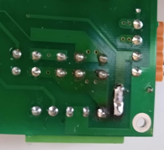
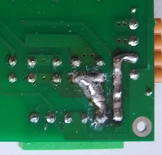
And here is the updated board. The common line is now beefed up from the input to the output connector, and the phase from the relay output to the output connector. (The latter looks a little untidy because it is covered in a clear potting polymer.) This seems to have done the trick and the board is running cooler. Plugging in the P=I²R numbers, a track resistance of 0.025Ω would generate 5W or so resistive heating, and this is enough to create a hot-spot of 50°C or so on a board without any thermal management of this size -- and this was the rough temperature that my DS11B20 was logging. Before and after
-
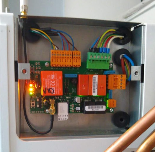
OK, the board was rather more damaged than I feared. Here are the before and after with the new connector fitted. The two RH pins below had got so hot that the through-hole liners very damaged and partially delaminated from the PCB, as had the RH trace. This is why I bulked up the track between the connector and the next through-hole component (this was the common a.k.a. AC neutral) The image below shows the refitted unit with is working OK. @JSHarris Note the crimped ferrule connectors I've got a DS18B20 taped to the replacement connector to see if I have any thermal issues, but it does seem to be working fine. PS. The 2nd pin (the 240V phase line to the heater) is getting rather warm. I think that this is because this track is probably also lifting near the pin. I will probably need to do the same trick and expose the track to the relay and bulk it up with solder. What I really need is a replacement board.

-
I've mentioned before about why I think that directly connecting any IoT device to the Internet is extremely dangerous, but if you don't believe me then watch this video. IMO, you should only open at most: an HTTPS port to a locked-down webportal and a strong authenticated SSH port, and possibly a VPN.
-
This reminds me. A 2-year post move-in check is to go around all of the sockets and switches to check the torque on all of the switch / socket screwed connections to make sure that none have deformed to the point of being a loose contact. I did this every 5 years or so one my old farmhouse -- mainly to check for dampness signs of overheating because we have 300 year-old stone walls -- but even so I'd occasionally come across a loose terminal thanks to deformation of the single core copper over time -- though the main deformation occurs on the virgin round core which is why I think it a good 2-yeear check.
-
On a different note, I've been reading up on the use of ferrules vs. alternatives such as tinning the twisted multicore (which to be honest is what I used to do). Apparently tinning is an absolute no-no. Why? Because a properly crimped ferrule presents a rigid cross-section whereas a tinned multiccore is plastic over time: it will deform and slacken off. Time to buy a crimping tool and ferrule kit!
-
You mean very like our construction industry approaches BReg compliance. ? The Chinese do it for consumer items. We only do for the housing stock that 95% of new buyers get.

