TerryE
-
Posts
3822 -
Joined
-
Last visited
-
Days Won
30
Everything posted by TerryE
-
Update on Energy Use Based on 4 years of Actuals
TerryE commented on TerryE's blog entry in The House at the Bottom of the Garden
It surprised me too. 🤣 Jan and I are retired. My son is only working a part week ATM, so we are in the house pretty much all of the time and my son effectively has his own bed-sit on the top floor. So we have 1 freezer (plus a small supplemental one brought on when needed); three fridges; 1 DW, 1 WM; our cooking is electric / induction; SunAmps for HW; MVHR and slab recirc; 1 gamer PC and 2 laptops on; tablets and mobiles of course, and 3RPis. All lighting is LED. The fridge/freezer in the utility is old, so it has a relatively poor energy rating, but it is not economically worth replacing. It seems quite easy to sustain 600-750W baseload for this lot, and that equates to 15-18 kWh /day. 😢 -
Downloading OVO Smart Meter Data
TerryE posted a blog entry in The House at the Bottom of the Garden
The OVO portal does have a publicly available RESTful API, but because the UI makes heavy use of Javascript (JS ) scripts to do the webpage renders and these make JSON callback to the OVO server, so it is quite simple to use your favourite scripting language to automata downloading data and aggregating it into a database or equivalent. I have written down-loaders for Python, and NodeRED (based on node.js) but I currently only maintain the latter. In essence your script will need to do a bunch of GETs which then return the JSON data that you need to parse, and one POST upfront to establish your login credentials. This script will also need to roll forward any session cookies as these are used to maintain the session context and authentication. I retro-engineered the request chain using a browser and web-tools window (typically Cntl+-Shift+I). (Hint: if you have two displays, then detach the debug window and move it to the second display, to keep things simple. Also set the "Persist logs" option to be able to track everything. Below is the result of my latest analysis, which was a useful exercise since OVO have updated their framework. My NodeRED flow looks like this and I've posted the JS code as a Gist: NodeRED Function to Download OVO Smart-meter Readings. The first two request are to https://my.ovoenergy.com to initiate the authorized session context. GET https://my.ovoenergy.com/login to initiate logon. On a real browser this downloads bunch of JS scripts that display the logon page and process the "Log in" button. These can all be ignores except the session cookies. POST https://my.ovoenergy.com/api/v2/auth/login. Post content is a JSON object with items; username, password, rememberme (boolean). Once authorized, the remaining request are https://smartpaymapi.ovoenergy.com. GET /first-login/api/bootstrap/v2/. This JSON object lists off the accounts used by the user (typically one). So either parse this or just use your known ACCOUNT. For a standard log on, the welcome page also generates a whole load of non-usage related requests, but the key one is: GET /orex/api/contracts/ACCOUNT. This JSON object lists off details of your contracts both electric and gas. Note that my smart meter is classed as ineligible for SMETS1 ot SMETS2 but is classed as "already smart"; I am not sure what this means but this could effect the format of the following requests for your analysis. You can now loop through requesting daily or half-hourly data: GET /usage/api/daily/ACCOUNT?date=YYYY-MM. This returns a JSON object with electricity.data[i] containing the values for day i+1 of the given month. The consumption cost, and rates can be used to calculate the standing charge, peak and off-peak use and cost. (If are up to solving a simultaneous equation. 🤣) This will work for any ACCOUNT that you've logged onto with the session. GET /usage?datePeriod=daily&date=YYYY-MM-DD&unit=kwh. This returns a JSON object with electricity.data[i] where i = 0..47 being the energy reading for that half hour slot. Note that for can only get energy and not cost data on a half-hourly basis. You can also use the next and prev parameters to chain fetches for a date range. In this case, the account context is maintain in a session cookie rather than a request parameter. I need to check whether this is set by the daily breakdown request. I assume that you can also do gas readings the same way. -
Update on Energy Use Based on 4 years of Actuals
TerryE commented on TerryE's blog entry in The House at the Bottom of the Garden
@ProDave, Accredited Installer route or not, we would still need to comply with the noise requirements complete with calculation sheets. We would need a BInsp to sign off on this and the danger that the assigned BInsp might just demand an accredited installer do the worksheet. Plus all of the fees of course. Also since the ASHP would only be 1.2m from our boundary fence and 7m away from the neighbour's nearest opening fenestration, we would need a quiet ASHP such as the Ecodan 5kW. This with the controller comes in at around £4½K. But another is that our house (even with the poorer as-built performance) is still factors out the operating regime and templates that most ASHP units and installers are used to. We need the equivalent of 1kW continuous heat at somewhere between 30-35 °C (max) into the slab during the coldest months (or say 8×3 kW if we want to use mostly E7 low rates). It is a huge thermal store and so will soak this up happily. My algo for this is quite simple: set the O/P flow temp to something sensible, say 32°C if can be set that low, though putting a decent PHE between the ASHP and the UFL circuits might simplify this gearing; turn on the ASHP demand; integrate up the delT out-return on the UFL to calc the heat dumped into the slab and turn off when the desired total kWh reached. Need to think more about the peak variation causes, but I'll reply separately on that. -
Update on Energy Use Based on 4 years of Actuals
TerryE posted a blog entry in The House at the Bottom of the Garden
As I have discussed on earlier podcasts and various topics, I have a Willis-based configuration for heating our low energy house, and control is implemented with a dedicated Raspberry Pi using a custom NodeRED application for our underfloor heating and SunAMP-based hot water. This system logs a lot of instrumentation temperatures every half hour and also any significant events such as turning on and off pumps and the heater. Our electricity supplier has been OVO for the last 4 years, and because we have a smart meter, the control application also includes a script to log on to the OVO Portal and download the daily usage data into the MySQL database. Because these latest energy hikes, we have decided to revisit the issue of whether it would now be cost-effective to install an ASHP in order to save on monthly electricity costs for heating. Because I have been logging all relevant data for the past 4 years, I can base this decision on hard actuals rather than some generic planning assumptions. The next two graphs summarise these results. The first is an analysis of our daily energy use (we have an electricity only house). What I have done here is to aggregate the 4 years of data by calendar month and split these into three categories: Underfloor Heating (34% or ~4,000 kWh/yr). In practice, we only heat off-peak and use the thermal mass of the floor slab and the house itself to smooth out the overall background heat levels. As I have discussed in other topics, this results in a temperature ripple of about 1°C which is quite acceptable given the reduction in overall all heating costs. Other Off-peak use (25% or ~2,900 kWh/yr). We also use a couple of small oil-filled electric heaters on the first and second floors for the 4 cold winter months. These output roughly 1 kWh and run on a timer (actually controlled by my home automation system). We find that 3 or 4 hours is typically enough to keep the upstairs acceptably warm in the coldest month; this also means that the UFH on-time doesn't need to run over into peak periods. Our resistive load white goods (the washing machine, dishwasher, SunAmp DHW) are timed to come on in the off-peak period. General Peak Rate use (39% or ~4,500 kWh/yr). Pretty much all of our baseload and direct hands-on devices: fridges, freezers, cooking, computers lighting, etc. Note that the 2 retired (out of the 3) occupants of the house spend most of May, June, September, October abroad; hence the dip in this general use figure. I find the annual variation on this base load a little intriguing ,and I am not sure why it is so high. Our live-in son often has his radiator on in the evenings when he's at home, and we do spend more time indoors in the cold dark months. The simplest ASHP implementation would be for slab heating only and would give a CoP of ~4 (as the circulation temperature is under 35°C) hence saving perhaps 3 mWh p.a. @ 18.86p/kWh or roughly ~£560 p.a. at our currently quoted OVO night rate. Given that we would need to use an MCS certified installer to exploit a permitted development waiver, I would expect our installation to be £10K or higher, so I still don't have a viable cost benefit case to go this route. Yes, adding pre-heat for the SunAmps would increase this annual saving, but this would complicate the installation, and given our volume of DHW use this would in fact worsen the cost benefit case rather than improve it. Another interesting point is raised by the following graph which I pulled from a 2014 Thermal Design post. The bottom line is that thanks to entropy, pretty much all of the electrical energy that we use ultimately ends up as heat within the fabric and airspace of the house. Given this, the overall heat losses (if you take December for example) are pretty much double what we originally estimated. The following can account for the majority of variance, but not all. We had to drop the U-value for the warm roof to minimise ridgeline heights keep the planners happy We added 60° reveals to our fenestration to improve overall light levels given the planners putting hard limits on our window sizes, and these some limited thermal bridging Winter solar gain is almost non-existent for our window configurations. As discussed in an earlier post, we had a cock-up in our slab design which created a thermal bridge between the inner ring beam (this supports the frame) and the outer ring beam (supporting the stone skin). We could only partially mitigate this during slab pour. We estimated that MVHR would have a recovery efficiency of around 90%, but looking at the inlet temp vs room, I estimate the actual recovery is nearer to 80%, that is double the heat loss. We run the internal room temperatures a couple of degrees warmer than initially planned. However the house is built and well established so getting any convergence is now unlikely. So the house performs as a low-energy one, rather than a true zero-energy one. And we still only put ~20kWh into our slab in the coldest months. -
Most commonly Microsoft Certified Solutions Expert but in this case a Microgeneration Certification Scheme certified engineer. The installation must comply with MICROGENERATION INSTALLATION STANDARD: MCS 020. In essence this determines the maximum noise level at the neighbours boundary. This is normally achieved by using a certified engineer to sign off the installation. The Planning Portal states that planning permission is not required if ASHP "equipment must be installed by an installer who has been certificated through the scheme using a certificated product" -- that is self-certification is not permitted. It also lays down other limitations. All other cases must be covered though a planning application, but whether your BInsp will allow self-certification is another matter.
-
If you use a warm slab (See MBC website profiles), though other specialist builders do these as well, then your main thermal store is the slab itself. Willis-only isn't cost effective for new build with current electricity prices. Better to go for energy efficient build and ASHP direct into slab circulating UFH water at ~35°C so CoP should be around 4. A few there have done this very effectively. The issue you will have is getting an MCSE installer to do this for you because their standard templates don't work for such energy efficient builds. However you don't actually need to use an MSCE installer as this can be signed off by your Binsp, esp is you have a private one. You just need to do all of the calcs to prove conformance to BRegs
-
MVHR Duct Design
TerryE replied to Triassic's topic in Mechanical Ventilation with Heat Recovery (MVHR)
IMO, a single correctly-sized system is always best and far easier to balance. Yes, there are circumstances where a split system might make sense for example a main house with a detached annexe, but not if you've got a single well connected living space of many rooms. If you are not careful and the two systems will just fight each other, and be really difficult to balance. -
The main source of sound is the pump circulation, and this depends on the flow rate that you need to dump the heating to the slab. You can either work this out using math, or by trial and error. In general you want the flow to be as low as you can get away with, as this will generate the least noise. In my passive house I only have three loops covering the entire ground floor slab and I can get way with the pump on the lowest setting. Our manifold is in a cupboard in the ground floor toilet, and I can just about hear it when sitting on the can. 🤣
-
As Peter suggests this doesn't really make sense practically. The manifold might only be 50cm wide but you've got the pump return on the LH side so you are going to have to cut out at least one stud vertical which will then need cross bracing top and bottom and the bottom bracing will then impede the UFH out and return runs. Have you got 60 or 40cm stud centres? If 40 then getting it in is going to be problematical. OK if you really want to lose your UFH out and return runs within the studwork, then you may be able to notch back the CLS uprights to 40mm and brace/support the two cutouts sections lengths of CLS at 90°. That would allow you set back the manifold and pump 50mm or so and allow the UFH pipework to run cleanly within studwork, but then so you will still need to box out the manifold and pump area with a shallow cover maybe 80-100mm deep. Even so, this is all very tight and for very little gain IMO. Also heaven help you if you need to do any maintenance !!
-
I never found any problems with internal corners at all: I don't mitre them but cut one with a negative profile, with the straight section using a (japanese) hand saw, and the profile bit done with a fine tooth jigsaw with a cut-on-pull blade on the reverse side (easier to draw the profile). No probs with tearing or breakout. We didn't have that many external corners so it was fairly easy to plan the laying sequence so that I could pre-glue and pin the externals and let them dry before fitting, with the far end being the square cut pair of any internal corner, so the piece can be overcut 5mm or so; offered up and cut exactly to fit. It's 4 years since we moved in and we've got no noticeable wear and tear yet.
-
We went with HDF skirting in our new build. I did all of the carpentry and fitting; Jan the painting. In previous houses we used pine. I found HDF easier to work, fit and paint.
-
Two comments on this What really matters isn't whether they've designed or even built passive houses, but that you visit examples personally and get the occupants to confirm that they perform to spec as built. Our house is the more boring variety but at least it performs within a 10% tramline of as designed. I've come across examples where the as-built is off by factors not percentages. IIRC, the self-builders bible has a rule of thumb: the cheapest house has 4 corners and a simple tented roof. Add 10% for each extra corner. Add 50% if you applying to Grand Designs; add 100% if you are selected to appear. 🤣 I repeat: get an independent QS to recost for as-built before to commit to anything!!
-
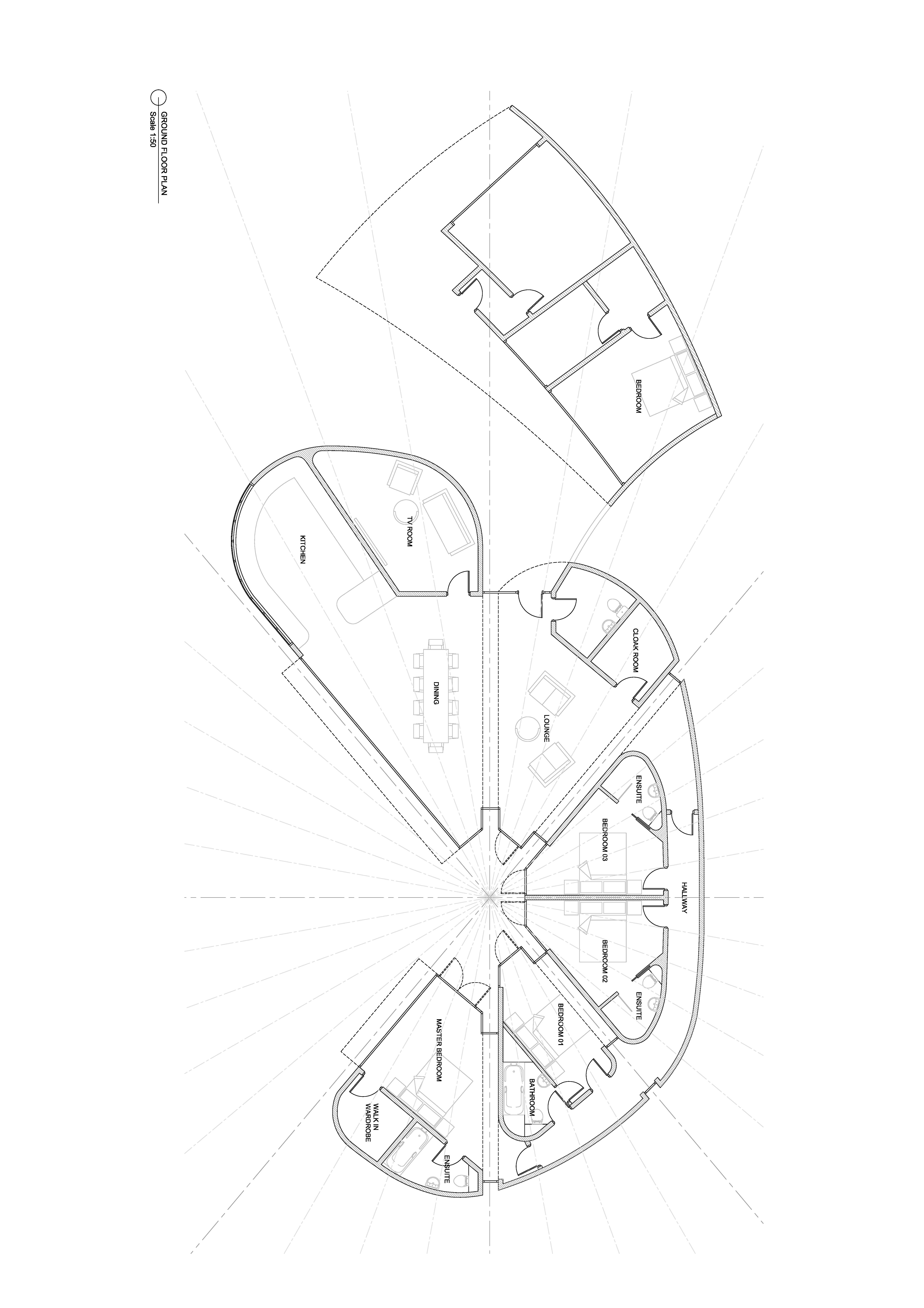
Your bedrooms seem awfully constrained given the total wallspace. Curves and none right-angles might look graceful on paper but are a total PITA when it comes to adding furniture / wardrobes / hanging space, etc. Heating must be UFH (which is the best choice anyway) as you will have no available wallspace for rads. Why not space out BR1 & 2 with a separating double wall (only one side will need to be load bearing) and split this into 2 walk-in wardrobes for the two bedrooms? OK, I see that you have a decent walk-in for the MBR, but nothing for BR 1-3 and this is especially the case given that you've got opposing doors creating round-bed access corridors. This type of layout could work if you are only two occupants with three guestrooms for short stay visitors. I see in another post that you are future proofing for a family. However no modern child, teenager or adult would be happy with this type of bedroom layout. Where could they fit a desk / home office / hang a TV / bookcase? What about privacy if their private space is accessible from both sides? Yes, the BRs could be used as offices, but dual use (that is also usable for overnighting occasional guests) wouldn't work with this layout. I strongly suggest that you get your architect to do a decent 3D realisation, dressed complete with a sensible selection of wardrobes, dressing tables etc, and you and your partner do a virtual in-room walkaround to see it it works in practice. Also the thermal design is going to be bad; really bad. I take it from the drawings that pretty much the entire south facing aspect is glass. (I say this because these clearly aren't solid walls.) Even with modern triple glazed glass the U-values are going to be 0.8 W/m²K or worse in practice if you are going for bi-folds, so the house if going to be expensive to heat in the winter and you need to double-check UFH design limits. In the the other seasons the house will turn into a hot-house. Airtightness is also going to be a real issue. So I feel that you are going to find it difficult to achieve current SAP requirements, let alone anything like passive class. I also can't understand the rationale for the S facing hub layout. It looks more like a circular bargraph than a clean arc. What's with the glass rebates? The rooms and the outside space and connexion to inside would work a lot better if the polygon formed at the meet of the room was more like a fit to a graceful circular arch. The extra floor-space in the formed in these reentrants isn't really usable anyway, and will add significant to the construction costs. What is the roof design and pitching? What are your ridge lines going to look like? I know this might seem harsh, but this plan looks to me like a concept that an inexperienced architect might come up without decent senior partner review. I think that you are going to be horrified at the build cost. If you want to go with this design, then I would suggest that you pay the extra $K or 2 to get a decent independent QS to give you an estimated low/medium/high total build cost before you go any further. You will also need to be really careful selection your builder and main suppliers. This is an unusual design and will require truly experienced builders.

-
I live in the new build opposite the Rose and Crown. 😊 PM me you want to hook up / trade experiences. Terry
-
Oops, I am the Wally: my answer was to the MVHR post that I was working on. Sorry. 🤣 The only running costs for the Harvey is the salt blocks as you say. Clearly usage depends on your water consumption and water hardness which will vary dramatically depending on geography and hence from household to household. We buy the 12 packs for £80 odd and these last around 4-6 months, IIRC. I can check with Jan what we use, as she does the reordering.
-
Yes, everything apart from cold drinking water, as tea and coffee make better with the soft water. Electricity on our current tariff is about 10p / day and filters are maybe £15-20 per 3 months so around £100 p.a. PS. Mike, it looks like I'm not the only one to cross post on topics. 🤣🤣
-
My experience is of a similar ballpark to @joth's analysis. Yes, the MVHR uses less than 1 kWh / day which is 1 kWh more than trickle vents. But we have a 3 storey detached house built to roughly passive-class standards. We are all electric and haven't installed an ASHP yet because I can't make a payback case. Instead we use a Willis to heat our UFH mainly on E7 cheap tariff over the winter months. Last year we used just over 11,000 kWh electricity in total (over 70% cheap tariff), so yes the MVHR accounts for maybe 3% of our total energy use, but the heat recovery is around 95% and without this our heating requirement would be around 50% higher, so this one is a no brainer for us. Not to mention fantastic air quality throughout the house and free drying room. @JohnMo We do the annual service ourselves and bulk buy the filters, so the maintenance cost is small beer.
-
We have a 2½ storey house with external stone skin, using an MBC provided and built Larson strut twinwall TF that is racked with a single 15mm inner OSB3 skin with 2 × transerve internal load bearing walls also racked. We had the full SE load calcs as part of our BCont docs. This has proved extremely solid with not even a single hairline crack in any plasterwork.
-
We have a heating strategy of keeping our house at the same temperature 24 × 7 (accepting the ±½°C ripple that I mentioned above), though one side effect of having a super-insulated house is that even in winter the house only cools by around 1°C / day if the heating is off. But the same thermal design process needs to be applied even if you live in a conventional low-insulation leaking house: If you are using UFH as your primary heating source then if your house looses X kWh / per day heat externally, then your UFH heating strategy must supply the same X kWh to keep overall heat balance. That (~7 × Δtemp × Area) W is a good rough estimate of how much heat the slab can throw into the room environment, so the more heat you need to input then the higher the Δtemp needs to be, though once this gets up to 10°C then the floor starts to get pretty uncomfortable, and you really need to worry about potential hot spots under in-contact furniture, etc. Higher rates of temp rise can cause heat stress in the slab which isn't a good thing. This is why IMO you want to insulate where practical and cost-effective and try to remove external air leaks and use MVHR as this will dramatically reduce your overall heat requirements. A more standard higher O/P slab will benefit from a TMV mixer and buffer tank design, though because the water circulating in the slab is a lot cooler than that in a radiator installation, UFH installations are a far better fit to ASHP installations. Last thing to remember if you are going for a non-constant Time-of-day profile, is the issue of time lag. With a 100mm+ slab (especially if the UFH runs are placed at the base of this) then the heat has to propagate through the say 80mm of concrete before the surface is at temperature and the floor starts to radiate heat into the room. This means for example if you want the house to be warm when you come home at 6pm, say, then you might need to turn the UFH on at 2 or 3pm and likewise turn it off at 9pm, say.
-
@SuperPav, Mesh selection is really a choice for your SE or whoever did your slab design and it is driven by that. Using the mesh as a placement framework for the UFH piping is really a secondary bonus and shouldn't impact on mesh selection. As to slab heating, there are broadly two strategies at the extreme: Dump heat into the slab at a steady rate so that the slab remains at a slight Δt above room temp. Here it will radiate ~ 7 ×Δt × A W into the interior. If this matches the net heat loss of the house, then your house will stay at the set temperature. Calculate your total kWh house losses for the coming day, and for a given input heating rate this give a total heating time. Just dump this into the slab in one or more "chunks", and accept that this will result in a slight ripple (say under 1°C) on your internal temperature. We have a passive house and have adopted the latter as this was easier to implement, in terms of kit required, ease of control, and simplicity leading to maintenance risks and reduction. The thermal dynamics here is a different Q entirely and one where I feel more qualified to answer on. I did my slab design back in 2015, and I was one of the first ones on this forum to go with a UFH solution which went against the prevailing wisdom of including a buffer tank. I decided to use a 3 kW Willis heater to heat the slab directly and use it as the thermal store for the heat. I needed to do some modelling of the slab for me to be comfortable with this solution and to ensure that it's thermal performance during the heating cycle was well within sensible limits, before finalising on this implementation. Luckily my professional background give me some experience of doing this type of modelling, but the main challenge was one of producing a model of the correct simplicity yet enough detail for the exercise to be meaningful. I have previously documented this in my blog posts and and specifically in my thread, Modelling the "Chunk" Heating of a Passive Slab written in late 2016. For the modelling, I didn't want to get into the complexities of CUDA compute engines and CFD libraries, so to keep the math and computation simple enough to be computable in Fortran on a single core (which is what I used back in the 1980s when I did this sort modelling for a living), I approximated the slab heated by one UFH loop as a (radially symmetric) concrete pipe some 0.120m in diameter and 100m long with a 15mm heating pipe running down its centre and with water circulating through it and heated by a 1 kW element before return. This allowed me to use a simple radial approximation for the Fourier heat equation and to solve over time for the (r, l, t) coordinates over time and the length of the pipe. (See this post for more details.) OK, it's a model and an approximate one at that because the actual heat flow through the pipe is not radially symmetric as the area around the heating pipe is insulated below, radiating to the air above, and adjacent to another. Even so, this did allow me to investigate the overall varying heating characteristics over time and both along and across the concrete. This was good enough to confirm that a "Willis direct into slab" approach would work fine for me. I subsequently instrumented the actual implementation with lots of DS18B20 digital thermometers which have been continuously logging now for ~5 years, and the slab behaves as predicted. This can be summarised by more simple and intuitive approximation. The slab surrounding a single pipe heating loop can be thought of a (folded) long box of concrete that is insulated below, radiating to the air above and with similar boxes on either side (since these are being heated by a return run at a similar flow temperature). The UFH pipe flow is dumps ~1kW (in my case) heat along the centre of this long box, and so the water cools as it flows along the pipe. The overall Δt is largely dictated by the water flow rate which in turn depends on the pump head, flow resistance, etc. In my case this was the biggest difference between the model and actual implementation, as I went with a slower flow rate than my modelled 1 m/s, in order to keep the circulation noise to a minimum. (The UFH is in a services cupboard off or G/F toilet and I don't like to hear the pump noise when I am taking a dump). So as the long "box" heats you get a standard radial heat flow curve where the circulating water in the middle is maybe 5°C hotter than the surface during heating period, with maybe a 2-3°C drop along the 100m run length. As the heat is dumped into the slab, it slowly but steadily heats up over the heating period, say by 5°C or so over a 7hr heating window. Certainly if you walk over the slab at the end of a heating cycle in bare feet (as we do), you can notice the 1-2 °C variation across the floor between the flow and return legs of the UFH runs and any gaps in UFH coverage. Pretty much as soon as the heating stops, the heat from the warm spots spreads so the feel becomes more uniform (as the heat only needs to flow ~50mm or so through the concrete). We heat our slab overnight, so by midnight the slab might be ½-1 °C below room temperature. In the morning after heating it might be 4°C above room temp, and it is now radiating ~28 W/m2 into the environment. This rate will fall during the day as the slab cools, leading (in our case) to a ~1°C ripple on the overall air temperature. The integrated heat dump from the slab must match the overall house losses, so the colder it is the more we need to heat the slab; and the warmer, the less. I hope this makes sense.
-
Your profile is similar to those of us that have MBC warm slabs. The rebar mesh was laid on ~40mm soldiers and the UFH pipe tied directly to the mesh. Have a look at my blog; there are pics of this. And others have similar. Absolutely no probs. Remember to tape the UFH pipe ends before the pour, to prevent dirt ingress. Our slab was laid in late Oct, so we didn't fill and pressure test until after the frame and windows were up and the structure airtight. BTW, I note that you have a cold bridge between the slap and the inner wall leaf. You typically put a small EPS upstand here to prevent this. Plastering out + skirting will hide this.
-
We just bulk-buy the salt block and have to remember to check the unit once a week or so and add another couple of blocks when needed.
-
How often do you need to descale your kettle etc.? We considered our water "slightly hard". Your local water authority should publish a water hardness by geo location report, and ours was harder that I thought. We have a Harvey Salt Ion exchange softener on all water as Nick suggests. Absolutely no regrets, as we next get scale in our appliances, taps, shower screens, etc. Remember that if you have any thermostatic mixers on any of your potable lines then these can fur up and fail if your water is at all hard. As Nick says, anything other than ion-exchange is just snake-eyes.
-
Rookies diving into the passive house deep end
TerryE replied to Jake Smith's topic in Introduce Yourself
On this one, a few of us have gone down a dissenting route and have been successful at it. I did the overall design for my house myself and spent a lot of time on the 3D visualisation to make sure that the internals worked as a whole. I then used a decent local architect technician to draw up the set of plans for planning submission, and put the money that I would have spent of architects fees into our TF and passive foundation by subcontracting a decent custom build TF passive house specialist firm (in our case MBC, though there are a few to choose from). I did all of the design validation myself. To be fair, I had recently retired when we started the build, so I could invest the time in doing the research and getting on top of all the issues. I do disagree with Mike on "PH experience doesn't matter". If you are going to invest in an architect's services then he or she should be competent to do what you require: although passive house design is any more difficult than classic UK build, IMO, it is just very different. For example, it is really hard achieving passive class performance with conventional foundations + beam and block floor + block and brick leaf walls. We used a warm slab (that is a floating reinforce slab with UFH in-slab on a structural EPS bed + twinwall TF with blown cellulosic filler: this technique achieves passive-class almost by design. Anyway have a browse of some of the blogs, and do your research. 😊 -
Why might my hot water tank not be working?
TerryE replied to jamieled's topic in Boilers & Hot Water Tanks
You need an electrian, though TBH is you own a multimeter, then this is probably something that you could buzz out yourself -- so lonf as you understand and are confortable with all of the 240V safe working pactices.