


TerryE
-
Posts
3822 -
Joined
-
Last visited
-
Days Won
30
Everything posted by TerryE
-
Anywhere where you think that you might need to put a screw in the floor.
-
My electrician used a plastic enclosure. I would have been a lot more comfortable with a steel one. ☹️
-
First I misread the Siemens datasheet. The input will accept 240V at a current draw of around 15mA so yes, this could be switched by the Pro SM4. The advantage of a Wifi based switch is that it removes the RPi from the scope of the inspectors review, though you should have the CE DoC to hand. The disadvantage of Wifi is that it doesn't work too well in a steel equipment enclosure. 🙃 Though you could try putting the RPi inside the enclosure as well In the UK, the rule are different. Your electrics have to be signed off by a Part P certified electrician who certifies the house registration and does this in an online registry so the Binsp (and insurance companies) can look this up. Once my electrician read the datasheet for the Crydoms he was happy to ignore the 5V control signals as these are outside the scope of the certification.
-
As it happens the answer is the same on both: you can manually set the post date and time on both, with the default as "now". Posts are listed in date order of the post date and time. You can edit any historic post and change its contents. In fact (again on both) you can hide a blog post. I do this when I am in the composing / proof reading cycle and I only publish it when I think it is good enough to be readable. If you look at my early blog posts, you will see that they pre-date the foundation of the forum. This is because I scraped the content of my posts from eBuild and set the DTS to be the original. @Rishard Sorry about this diversion, but that is what we old farts tend to do. You have to take the rough with the smooth. 🤣
-
@ProDave, Your blog is a Wordpress site so you can just paste in Rich text content into the standard editor or if your posts are in Word format there are a range of add-ins which will be decent conversion for you.
-
@Mike, you need to be careful in selecting SSRs both in terms of input and output specs. The Cyrdom's take a TTL compatible input and so can be driven directly by form Arduino micros or through a 3.3V to 5.V level shifter. I drive mine through MCP23008 multiport I/O expanders which can run at 5V and can drive the SSR inputs but interface to the microprocessor using 3.3V I2C. The Crydom range seems to be one of the few which match these requirement, but you do have more choice in the Panel Mount format such as the Cyrdom 1 Series (datasheet) which can also be directly driven at 3.3V and they are cheaper too. The Siemens models you reference are really optimised for industrial use and take 40V AC control inputs which means you will need a 6:1 step-down transformer and a separate way of switching the 40V AC input signals getting a USB or RPi SSR board capable of driving 40V AC is a PITA as most AC SRR boards quote 100-250V operating range. However you have a rich choice of relay boards which will happily drive at the 40V few mA that the Siemens SSRs take.
-
I can't answer for @ProDave, but his off-forum blog is Willow Burn Blog. Unfortunately a lot of the earlier content was on Dave's blog on another self-build forum that was shut down by its owner in 2016. Dave didn't scrape the content before the site went offline so the only access to the content is on the Wayback site, such as The Only Way is Up, but unfortunately Wayback only scraped the text content and not all of Dave's lovely Pics. ☹️
-
@Mike, I did the same. I use the 20A versions and my loads all pull just under 12A so I am at the limit of the CKRX2420 spec at 60°C. I did just think of putting a 5V 100mm quiet fan below the SSRs to give a bit of forced are circulation over the fins to see if this made any significant difference. PS: I do find the nominal ratings of these devices very misleading because at 20A, say, the device needs to dump about 7W and there's no way that this would stay under 60 let alone 25°C without having forced airflow over the finned areas.
-
@Nickfromwales Nick after you gave me so much help with my build, I am glad to return the favour in a small way. Yes, I've had 2 SSRs fail; one failed safe on and one tripped its MCB before failing. I never bothered to implement the contactor approach. We discussed the root cause on another topic: Because these Crydoms run hot at ~55-60°C, I recommend avoiding wiring any multicore leads (chrimped or not) directly into them. I have a separate connector strip in my box and I run a 4mm single core link from the SSR to this and wire the (chrimped) flex power lead into this. This way both leads into the L1/T1 connections are 4mm single core. The connector strip runs cool (at only a few °C above ambient) so I haven't had any issues since.
-
We had to run our foulwater drainage pretty deep because of the sewer level at street. We also had a 750mm trench for water and electricity into the house. These trenches were ~450mm wide because that was the bucket my builder used to cut them. He also filled these with type 3 MOT (IIRC ~3-4 cm broken gravel) -- about a 20 tonner's worth -- with about 100mm MOT 1 topping below the sharp sand bedding for the blockwork drive. The BInsp didn't seem to care. (He had a very good relationship with my builder 😉) It works really well, and even the worst deluges soak away happily.
-
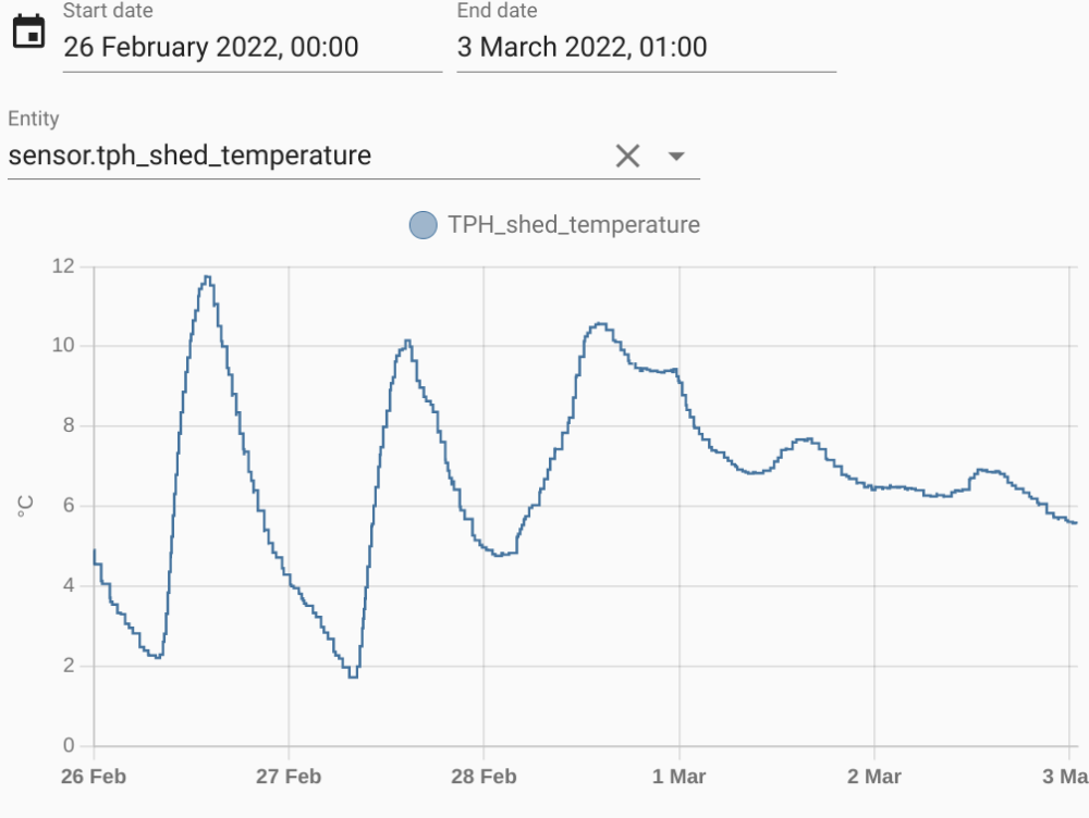
If you have a flush meter box in your outer skin then another alternative is to put in there. I also have an Aqara ZigBee temperature and pressure sensor in my garden shed, which feeds into my RPI4-based Home Assistant setup. Below is a quick screen grab from HA, but the data goes back a couple of years in InfluxDB. The shed is unlagged so tracks outside temperature well, but the sensor if in a dry environment.
-
You really need 200mm min and preferably 300mm depth for Cellulosic filler to get down to a U-value of 0.12 Maybe to way to go is to use pre-cut lengths of Steicowall (see here ~P38 or equiv to make up the wall cassettes. At least one of the member here ? @ProDave ? made up his own panels onsite. We have an MBC TF house with this general profile albeit using Larsen strut box sections and cassettes pre-made in factory. 👍 on the battened service cavity. The vertical were on 400mm centres so the OSB was but jointed every 3rd upright and then taped. The battening then sealed the joint totally. The service cavities made running electrics, plumbing, etc. an absolute doddle.
-
Nick, I did initially think of having an SSR and contactor in parallel, and using my control system to do a sequence of: <SSR on><Contactor on><SSR off> .... <SSR on><Contactor off><SSR off> And that way the SSR would only be on for a second or, but the Contactor wouldn't be under load during the switch, but I discarded this as being too clever. IMO the weakness with the CKR range is that they rely on convective airflow for cooling: IMO in retrospect you'd be far better off with the surface mount style directly mounted with thermal paste on the steel equipment enclosure, and here you would be using metal-on-metal thermal conduction to convert the entire enclosure (say ½m² area) into a thermal dump and the ~5W waste heat would only raise the case by a couple of °C.
-
Like the grave 😊 Triacs don't make any noise, as they do the switch as the AC crosses 0V. Remember that they only have an efficiency of ~99-99.5% and that ½-1% ends up as heat, say 5W @ 12A, enough that you may need have some sort of thermal sink.
-
Wet plaster is a big help, and I can understand your reasons for adopting a familiar construction technique, but you also need to address the main vulnerabilities that can lead to bad thermal bridging / air loss. A couple of examples: The inner blockwork is on the warm side of the thermal gradient. You don't want a thermal bridge to the ring foundation that carries it. Using something like Perinsul Foamglas blockwork for the couple of courses that span the FFL will dramatically reduce the bridging. Don't mount your joist direct into the inner blockwork leaf, but rather place in wood fillers when blocking up and then fit and seal joist hangers during first fix. This way you avoid all of the airgap risks. I am not saying this is the best way for you and your brother , but what I am saying is that you need to identify the risks and decide on construction approaches before you start the build rather than putting in retrospective mitigations.
-
Try this 😊 Also picking up @Iceverge comment. You will see in some my blog posts that I ended up using this sort of approximation. Worked fine and let me play with design trade-offs on elements and construction techniques. You really need to get U-values under 0.15 or so and have decent (e.g. triple glazed) fenestration. This involves avoiding thermal bridging by design, and as Iceverge says, going TF for the inner skin just makes everything so much easier. Another factor is that once you are in this sort of thermal domain, air losses rapidly dominate so you need to go for that ~0.5 ACH target and MVHR. It is really rather hard to get this sort of air tightness with a blockwork inner skin, especially if you have dot & dab boarding out: you are really too dependent on the quality of the bricky's work. Spending a few days following through other build experiences here will save you a lot of tears and money.
-
Perhaps the easiest route to low U-value walls is to use an internal timber frame. A lot of companies will prefab these in factory and ship to and erect on site. We used MBC (with an outer stone skin, because it was a planning requirement), but there are other vendors referenced in various topics. Single wall TF is cheaper an will get you to 0.15. Twin wall is airtight by design and will get you to 0.12. Other have used techniques such as ICF, and even conventional block inner with a 200 gap filled with Rockwool both of which should give you ~0.15. Getting airtightness with an inner block leaf can be a bit of a PITA though. Again lots of discussions on this.
-
I did a least squares fit over the first years heating days to get my first order functions. But remember this is a control algo with feed forward and feedback terms, so if it does put 5 kWh too little in for one day, say, then the the average house temp drops by 0.1°C and the 5 kWh is added in to compensate on the next day. Hence (visitors and offsite visits aside) the daily average temperature rarely drifts by about a 0.1°C 1-sigma. The only reason that I haven't put in the visit compensation term is that it just isn't worth the hassle.
-
Luckily I still remember enough of my stats modules 48 years on from my undergrad days at Cambridge -- which more than can be said for my daughter who did maths with stats at Oxford 30 years later. ?? So what you propose as the null hypothesis? A constant set-point? This isn't our goal. The reason for the ripple was a policy decision trading off the temperature tramline to save on overall heating costs: We cut our heating bills by about 30% by doing our heating using E7 off-peak vs single rate tariff. Yes having 22.7 ± 0.5 °C wastes under a kWh compared to a tight 22.4 °C, say, but we don't really notice the ripple; I do notice the savings on my electricity bill. This is fundamentally a control system problem. I look at the temperature plots over the winter months and the system is remarkably stable: essentially the same temperature throughout the house 24×7. We love it.
-
The stats are all aggregated in Home Assistant and Jan and I can look at these through a browser or the HA app. TBH the biggest bumps (about ½°C before the feedback term kicks in) is when we go away for a weekend, say or have guests to stay (about 3kWh per person plus extra cooking ....) Other than that the ripple is remarkably stable.
-
@SteamyTea Nick, that's a typical daily ripple during winter months. The time constant of heat flow through the walls is ~1 day so I find the Met office forecast is good enough.
-
Peter, thanks for the prompt to this interesting discussion. My only quibble is with the verb "tried" ? I would say that the system has been working really well for over 4 years now. IIRC, you have a pretty energy-efficient house with decent internal thermal mass. This puts you well outside the operating domain of most standard controllers. A good indication is the 24hr heat-loss without heating (mine is just over 1°C per day). I use two straight-line functions to calculate total daily heat requirement: Planned demand in kWh as a function of Δt: (set-point - Met-office predicted temperature) A feedback adjustment as a function of Δt: (yesterday's average room temp - set-point temperature) When you schedule the on times isn't that critical. I do mine overnight so I get a ~1°C ripple over the day. Moving a chunk to an afternoon boost would drop this to nearer ½°C I am not sure that you really need some fancy (and expensive) controller. An RPi zero 2 controlling a relay or two would be perfectly adequate.
-
What is the point of the faux garage? If you want a store room then having an internal store room / box room / drying room would make a lot more sense. If it's in lieu of a garden shed, then this is going to work out as a very expensive garden shed in terms of floor area. Just stick with a small garden shed for the garden stuff. If this is a self-build then scan the forum on building passive standard or near. We have one: all the rooms are the same temp within a degree or so; it costs little to keep it cozy (22½ °C everywhere). You'll need decent insulation for slab, walls and roof to get the U-values under 0.15, air tight by design, MVHR, under floor heating. You also need to think about services and their placement and service runs. Lastly think about low maintenance for the exterior: for example we have Alu-clad fenestration and black powder-coated eves and verges. No more external pain peeling or redecoration before we kick the bucket!
-
? ? Don't worry. I think you're one of the good guys. And yes, rereading I think that I did misunderstand your thrust.
-
@SteamyTea, either way I would be very uncomfortable leaving a 12A load connected through a standard UK plug for many hours overnight unattended. They just aren't designed for this type of use. Seems a recipe for a fire where the insurers could reject the claim.


