


TerryE
-
Posts
3822 -
Joined
-
Last visited
-
Days Won
30
Everything posted by TerryE
-
I started a related topic, IoT / microcontroller based power switching back in 2019, but a lot has changed in this last 5 years both in terms of the commercial off-the-shelf (COTS) products available to approach this; in my own attitude to doing custom development; and lastly in the actors on the forum that might want to input their thoughts. There is also a steady stream of new members who want to implement this sort of approach. There is a spectrum of options here, so let me list three sweet spots, and what I want to do in this topic is to focus discussions on the last one: A full IoT HA installation. Here I am talking about a Loxone-type system, the sort of installation that @jack has and where you want a soup-to-nuts home automation. This sort of system needs professional installation and certification, so you are probably talking about maybe £5K+ for the kit and another £5K for professional services, so quite an expensive option. Consumer-grade IoT devices. At the other end of the spectrum, there is a huge range of end-user kit and devices that are treated as outside the scope of Part P notification and certification. This area has really blossomed in the last 5 years with the explosion of systems such as the RPi-base Home Assistant, a plethora of ZigBee and Wifi smart devices, many also Alexa and Google Home enabled or with other cloud-service enabled functionality. Technically aware homeowners can use these to do a lot of home automation without falling foul of Part P Building Regulations. However, in terms of power devices whilst the standard UK socket is rated for 13A and can comfortably take this load for short durations, I personally would never leave even a 2kW device plugged into one for long term unattended use. Installation falling with the scope of Part P. In my case I have 3 × 3kW resistive heaters and a UFH pump that I want to control safely and legally, and at a sensible cost (that is without needing to install a Loxone system), but this work definitely needs to integrated in the house's wiring fabric and must comply with Part P requirements. So what are my options for work in this last category? (@ProDave @Nickfromwales and the other relevant trades experts on the forum, I would value your views / sanity-check on what I say here.) First some observations. In my case I have a good relationship with an electrician who did my house wiring and is Part P approved for signing off wiring modifications. He is a good but traditional sparky so I would need any mods to be well within his comfort zone for him to sign off. I am more than happy to leave the 240V stuff for him to do. In his case he is quite happy to wire up components such as relays so long as they come from a reputable UK supplier and have the correct certification paperwork, but he definitely would be a lot more unwilling to put his name to some power connectors sourced directly from China such as the SONOFF Smart Stackable Power Meter range even though these do have proper CE certification, and good build quality. As far as I read it, almost any wiring that is part of the building fabric falls within the scope of Part P. The explicit exemptions include coms wiring such as telephone lines, but even PoE is a grey zone. However, the primary aim of Part P is to ensure Fire and Personal Safety and there is a category Extra Low Voltage (ELV) that covers wiring such as 24V DC circuits,, and the risk here is very low (but still not-zero). The main point for me is that my electrician is a lot more relaxed about 24V (or lower) control circuitry. In my last topic on this, I ended up using DIN rail-mounted 240V 20A Crydom SSRs that are driven by 5V TTL logic to do my power switching, but TBH they have proved a total PITA, as they throw out about 60W waste heat at full load and so they run just so hot, which then causes various thermal problems. In retrospect since I am switching 12A AC1 loads, a decent relay is perfectly good enough such as the Finder 22.21.9.024.4000 are fine for this job and they only chuff out 3W. (AC1 includes straight resistive loads such as immersion heaters. Heavy AC7b loads such as motors or ASHPs are a different ballgame and would probably require using a contactor). These relays are driven by 24DC coils, so I can drive all of my control logic from a single 24DC supply. So how do I implement the 24V DC control circuitry? One option would be to add a MOSFET relay driver hat to an RPi, but my preference would be to stick with a dedicated I/O front-end processor, such as the Kincoy KC868-A8M switch, but my current choice is the Sonoff 4CH Pro R3. Both can run off a 24V supply and can drive 24V DC control logic. Being ESP32-based they both can run standard Open-source Tasmota, ESPHome and ESPEasy firmware builds. All three of these connector apps support MQTT as well as allowing you to set up failsafe watchdogs on any relay open commands. I have more to cover, but I'll break his post here for others to comment. @MikeSharp01, that includes you 🙂
-
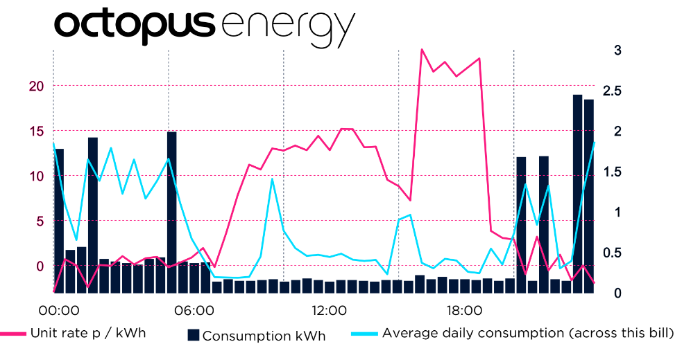
Nick, surely any form of efficient ToU heating should rely on a number of factors: Your house as a system should have a reasonable thermal inertia, passive or active, so that you can decouple the timing of heat input from the largely externally-driven heat losses. This BTW is an intrinsic property of my house design with its passive warm-slab, and 30 cm cellulosic wall insulation: I can pretty much top up the heat in the house at any ToD and the worse that I see in room temperature ripple over the day is ~1 °C. To make use of a ToU tariff you must have some predictive model, say covering the next 24 hrs, of what your input needs are going to be based on an external weather forecast for temperature, and possibly other factors such as sunshine, windspeed, etc. plus a corrective feedback trim depending on the delta between your target average room temp, and the historic actual temp over the last 24 hours, say. For us the external temp forecast and a trim correction works fine. If you are using resistive heating then relating heat requirements to electrical input is trivial, but with ASHP you will need a reasonable CoP predictor based on external weather etc. so that you can map your predicted heat requirements to electricity input. I do this type of modelling automatically at 11PM each night and then use the Octopus Agile tariff for the next 24 hours to allocate an optimum heating plan for the coming day. So here was my Agile cost for Christmas Day. OK, we were visiting my daughter and family so this was a "sustain day" where the system was only maintaining the house and HW temperatures, but the 23 kWh the system used only cost me 37p.
-
Nick, really interesting stuff but I am a little confused about how this relates to "Running an ASHP on a ToU tariff". Perhaps you could link the dots for this old dummy?
-
Mike, you can get refurbed 8Gb Lenovo M73 Minis for £50-100 on eBay. Set it up as a ProxMox host and run the HA VM on that.
-
I use a little star connection board with 3 pin connectors one-per-thermo, and run the individual OW thermometers back to this. IIRC, I had to bump the pull-up resistor to get it stable.
-
Nick, have a look at the Datasheet for the MLX90614. It runs a proprietary 2-wire protocol that isn't quite I2C. This might confuse the RPi I2C driver, but the easiest is to have a look at the various MLX90614 on RPi YouTube videos, e.g.
-
Anybody used ultra wide monitors
TerryE replied to Adsibob's topic in Networks, AV, Security & Automation
Welcome to the world of Windows. Not an issue with Linux, ChromeOS or iOS -
I have a passive class house which make things a lot simpler. Once a day my CH system calculates the heating required using a couple of 1st order linear functions: one heat required as a function of forecast external temp, and a feedback adjustment on the delta between the average internal temperature over the last 24 hrs and a target set point. This comes up with a total amount of heating energy required. This if the external temp is below a threshold, this is split 80:20 between the slab UFH and an oil-filled rad on the 1st floor landing. Because I use Octopus Agile, it then allocates the heating to the cheapest half-hour slots, so if I need 6 hrs of slab heating, say, then the scheduling will pick the cheapest 12 half-hour slots. These are usually (but not always) sometime between 11PM and 6AM UTC. This is all easy because my heaters have a known heat O/P and my house has such a high thermal mass that it only makes a tiny difference to the heat ripple throughout the day. Doing this would be a lot harder when using an ASHP where the actual heat output is hard to predict or measure and also in a more traditional house where the heating time constant is measured hours rather than days.
-
Fabric and ventilation heat loss calculator
TerryE replied to Jeremy Harris's topic in Heat Insulation
@Adrian Walker, a bit off topic I discuss this in my blog posts, but to summarise for your Q, I have added the manifold out temperatures. This is a Home Assistant plot. My CH system is a standalone RPi running Node-RED. It publishes temperature and other stats ½ hourly to my local MQTT instance and these are tracked by HA, so the jaggies in the plot are partly because of the 30 min subsampling, and partly because the heating is only on when the electricity is cheapest. (Octopus actually paid me to heat the house on a couple of days over the Xmas break.) As you can see the out whilst heating is ~4°C hotter than the return and the temp gradient is pretty even along the loops so the UFH pipework peaks at ~6°C hotter than the slab surface during heating. The heat flows out radially from the UFH loop throughout the slab and within 15 mins of so of the heating stopping the bulk of the heat has spread pretty uniformly throughout the slab at around just over 25°C or 3 °C hotter than room temp. It is noticeable and Jan really like padding around in the kitchen in her bare feet in the morning when the slab is at its warmest. My ripple is was little more that J's: when I measured it with a spot IR temp meter -- about 1°C.- 204 replies
-
- 1
-

-
- heat loss
- ventilation
- (and 4 more)
-
Fabric and ventilation heat loss calculator
TerryE replied to Jeremy Harris's topic in Heat Insulation
@Chris D, I have a warm slab (essentially 17 tonne of slab + another 10 tonne ring-beams wrapped in 200-300 mm EPS) with the UFH loops running in the slab itself. The house is a near-passive design so the slab only needs to run about 3°C warmer at its surface to provide enough space heating to keep the house at ~ 22½ °C which is what we like. Here is a plot of the last 7 days manifold out & return temps: I do my heating using Octopus Agile. The CH algo calculates the total heat required daily and heat the slab at the cheapest ½hr price slots, which are mostly (but not always) in the overnight period -- hence the jaggies. The house is treated as a single zone. Currently the return peaks at 26-27 °C and decays to room temp through the day. The outs are ~4°C hotter during heating. With your house, you will need the slab to radiate more heat, and a conventional heating control will tend to keep the temp in tighter tramlines so the core of the UFH will run hotter, say 30°C, with heat conducting up the surface and then radiating into the room from the floor, but also a lot conducting down through the subsoil because you don't have that 300mm EPS layer. Given that the P/A U-value estimate is relative to external temperatures, then you could be looking at a Δt of maybe 25 °C when you are heating the slab, or 25 × 0.5 × 250 W loss or 3 kW or up to 72 kWh / day of ground heat loss on top of what goes into the house itself. So you need to do your figures carefully. The bottom line is that putting UFH in an uninsulated slab is nearly always a very bad idea. ☹️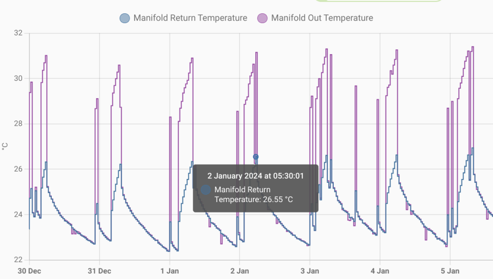
- 204 replies
-
- 3
-
-
- heat loss
- ventilation
- (and 4 more)
-
Fabric and ventilation heat loss calculator
TerryE replied to Jeremy Harris's topic in Heat Insulation
OK, my bad. Having scanned the BRE paper and the CIBSE paper it references, this treats ground leakage as a semi-infinite heat flow to ground and that, given a large enough area, this is negligible (in the limit). The IP3/90 (P/A) and (P/A)² terms are curve fit approximations which reflect edge and corner leakages and these heat flows dominate the losses. Note this is all rough order empirical estimation, and as @Redbeard's reference state "On a cautionary note it must be stressed that the following table is based on approximate calculations as detailed above and is for guidance only. It is intended to help give some ‘feel’ for insulation requirements". So @ADLIan's advice is better than mine. 🤒 -
Fabric and ventilation heat loss calculator
TerryE replied to Jeremy Harris's topic in Heat Insulation
Eh? This is about 10 × smaller than the radiant equivalent. It doesn't pass the sniff test. What is the source for this statement? -
Fabric and ventilation heat loss calculator
TerryE replied to Jeremy Harris's topic in Heat Insulation
Picking up @JohnMo's point, your floor is acting as a near to perfect heat sink. However the ground temp under the house will be in the 8-10°C range. Hence a bare or tiled floor will soak up about 6-7 W/m2K so if the Δt air:floor is 10°C that's 6×10×250 W or 15 kW and that's 24×7. That's nearly all radiant, so the "heat rises" adage, as John says, just doesn't apply. However, adding a decent fitted carpet and underlay throughout will make a big difference as this in practice is the main insulation layer. How much is moot. I suspect maybe 2 or 3 × factor reduction. -
Not just any relay, you need a decent SSR or contactor rated at 240V AC and 16A load for a 3kW resistive load, and wiring these up needs some electrical knowledge, as it is quite easy to do this in a way that breaches code. I played it by the book and got my sparky to do the 240V stuff and sign it off. I used SSRs so I could drive them with 5V DC. You can get contactors that are driven by 12 and 24V DC. You don't need low voltage stuff signed off.
-
We have a democracy in our house. It's just that Jan has 1.1 votes. 😉 What she hates about the SunAmps is their unreliability (due to control board failures): we are both in our 70s now, so reliability is becoming more important than ever. TBH, if we were in the situation of @Cooeyswell and only had one unit then we would have given up on the SAs long ago. We have been looking at our utility room and we can fit an OSO tank opposite the toilet; a job for next summer, maybe. This needs more mulling time to refine options. @MikeSharp01, I really like the idea of the SunAmps and the physics behind them, but they seem to be really let down by the engineering implementation. 😪
-
@SteamyTea, I just checked the SX 210 - VIP model which has a 193L water capacity. The heat loss is 1⅓ kWh / day which is about 30-40% higher than 2× SunAmp PV, but I could live with that. The killer (for me) is it's dimensions (1.3m high × 0.58m). I can't put it on the deck because of the other stuff in the services cupboard that I can't move (the UFH pipework, manifolds, rising main, etc. so it would have to go on a shelf -- pretty much in the same place as the SunAmp. I have 600mm depth to work with so it would be very tight, and I'd have to move my Control Panel. And then the OSO is a UVC so all plumbing would need to be done and signed off by a certified plumber, so he or she would need to sign off the installation. So this isn't an easy refit for me. ☹️
-
In our case, all of our services are in a small cupboard off the utility room toilet. We would have difficulty fitting in a cylinder and the hot losses would turn the toilet into a sauna. And @MikeSharp01, I will talk to SunAmp first.
-
That SunAmp PV of mine has failed again, so I am down to 1 × SunAmp PV again. It looks like the safety thermostatic cut-out has tripped again. No good reason. I had a DS18B20 on the heater wall and it never got near a cut-out temp threshold. I like the unit but the control electrics board is crap. I am seriously considering replacing it by an off-the-shelf ESP32-based control board, and reimplementing to control myself.
-
Logging OVO Actuals Data and Octopus Agile Half-hourly Prices
TerryE replied to TerryE's topic in Boffin's Corner
There is a Feb 2019 Octopus blog post, Agile pricing explained, that give a lot more detail on the makeup of the pricing formula. They've since tweaked on of the coefficients for later contracts and hence the formula for your contract is available on your account portal. -
Logging OVO Actuals Data and Octopus Agile Half-hourly Prices
TerryE replied to TerryE's topic in Boffin's Corner
@Alan Ambrose, another way to look at it is that OVO seems to use a ~3× markup instead of a 2×, but instead Octopus puts a premium on the 4-7PM window. Our use is pretty flat outside the 0-7AM windows so I would take the 14p peak premium anyday for cheaper prices (overall) for the rest of the day. -
Sorry to hear that. Maybe ask them to scan this post. 🤣
-
The drawing above shows 50mm insulation. However 150mm EPS has a U-value of around 0.2 W/m2K. Can you get vacuum panels formed on the curve, or AeroGel blanketing. You'd need something like this to achieve this. My other cry here after my SunAmp on a shelf experience is: Maintenance Access!!
-
If I remember what @Nickfromwales said, they've pared down the UniQ design. Instead of using a heating loop with pump and (external to cell) inline water heater to heat up the salt cells, the UniQ cells have an electric heater in-cell. The upside of this is that the engineering is significantly simplified, but the downside is that if the heater fails then it might not be a simple field replaceable item. Maybe a more knowledgeable UniQ owner can comment. TBH, if my current PVs failed or became End-of-Life unrepairable then I would still have SunAmp at the top-of-list as a replacement supplier.
-
@Russdl, if you take the lid off, it is an inline Y intake filter located above the heater (on the opposite side to the entry ports). On mine, the maintenance access port face downwards so it isn't easy to maintain or to access and you need to remove the side panel to do so, so you need the unit cold first, ...
-
Yes, there is one inside the PV models on the recirculation path, but not in the UniQ ones AFAIK.
