


sharpener
-
Posts
1487 -
Joined
-
Last visited
-
Days Won
1
Everything posted by sharpener
-
Small ASHPs / Units primarily for DHW
sharpener replied to Conor's topic in Air Source Heat Pumps (ASHP)
Natively it does HW priority (like most other HPs) which de-powers all heating circuit valves. There is a Parallel Cylinder Charging mode which you can engage if you particularly want to do both at the same time. But why would you? IMO best time to heat the water is in the small hours on cheap tariff, this utilises the stored water for timeshifting and interferes minimally with heating. Top up in the afternoon if reqd as the OAT is typically higher then so you get slightly better CoP. -
I would not recommend Bristan. Their basin waste corroded through in < 5 yrs, replaced under warranty. Looking at it I think the casting was a cheap zinc-rich alloy not proper brass and there was intermetallic corrosion between it and the brass nut. The shower head had an array of jets moulded into a rubber plate, when new you could massage the rubber and all the limescale would come out. After a year or so it became brittle and all the little rubber jets started to break off. Their bath taps have worn so there is too much travel; after turning them off you have to rotate them back a bit or they drip. The shower/bath pull selector leaks, dismantling and cleaning with de-scaler works for a short time but it recurs and I have given up. Out of four fittings only the basin mixer tap is OK after a few years.
-
Don't personally like flexis much but have had no problems where they were necessary. They have been used on the Continent for decades. A lot of satisfaction to be had from DIY, you can take your time over it and choose your fittings not rely on what is in the back of someone's van, often the result is to a higher standard than a professional would have left. Also you end up with a much better knowledge which helps enormously with fault-finding, and you are not paying someone for the time taken to trace and understand the plumbing in your own house.
-
Continuous ducting, mains supply, Southern Water
sharpener replied to Del-inquent's topic in General Plumbing
10 yrs ago Cambridge Water Co replaced my lead supply f.o.c. and were happy to have my supply pipe laid in a scrap length of 50mm waste pipe where it passed under the front wall of the house. Annular space was filled with metal mesh both ends to keep rats out. They didn't insist on duct under the suspended floor. Also said that 450mm deep was adequate for DIY but would have insisted on 750 min if my builder had done it(!), don't understand the logic but was grateful for the concession. They originally wanted 25mm MDPE but I had a load of spare 20mm, so they fitted a reducer and a stub of 25mm on their meter. Haven't had any problems with flow rate for a 3 bed house (internal h & c pipework is all in 20mm copper as far as the bath taps). Overall I was very pleased with this sensible outcome. Seems things have got a lot tighter since then. -
If you are planning to replace the existing pipes with new copper then 22mm probably more than big enough. I was happy with fitting 22 Cu as far as the unvented cyl, though it was previously OK on a 1/2 in lead supply jointed to 15mm copper for the rising main as many Victorian houses are. OTOH if you are going to use polymer pipe as easier to work with then worth keeping with 28mm as the capacity is only about 2/3 of the same OD in Cu. Good calculator to play with here. Would be interested to know what treatment/filration plant you have fitted in yr outbuilding.
-
Thanks. And that is for 3.5kWh. A 260l tank from Newark will store 9kWh for me, and even filled with 20% glycol will cost a small fraction of that. As the principle is well established and SA have had the formulation of their 58C phase change material sorted out long since, it is a mystery to me why the engineering of the product seems so poor and there is no effective competition in this marketplace. (The mix of compression, soldered and Speedfit fittings described earlier sounds like a test rig thrown together in a university lab not an engineered product.) The USP seems to be the compact size of the units, but it must be a very small property indeed that has no space for a hw cyl. Even my first flat had an airing cupboard with a Fortic tank in it.
-
Flamco also make phase-change thermal stores. At first sight there are some similarities to the Sunamp e.g. the diagonal arrangement of the four pipe connections. No idea about price or availability in the UK.
-
Sounds like it might have been very old and needed a new cable, and maybe a new service head, so it kinda makes sense if you are going to dig anyway. But the original cables were quite generously proportioned, if in good condition they will happily take uprating to 80A, have had that done in the past, don't know about 100. BTW not a peep out of the OP either here or on the PV board, hope he is happy!
-
What kind of upgrade though? If you have an 80A supply and ask for 100 they will (subject to various checks) just change the fuse for free. I wouldn't have thought they would put in a new 3 ph cable f.o.c.
-
One thing no-one has mentioned is that an ESS inverter should be protected by an RCD which it does not share with any other circuits. Several of the systems upthread do not comply with this.
-
For a 250 sq m new build you are unlikely to need 3-phase, a typical 100A supply would cope with solar panels, EV, heat pump, battery system. But some DNOs are fitting 3-phase connections now as standard as I have heard.
-
So yes, Vaillant's schematic is treating the SA just like a hw tank. SP1 is the input for their usual VR10 thermistor sensor on/in the tank. AFAIK it's not an input that can accept a demand signal from voltage-free contacts. Maybe they just are using it to short out the sensor inputs, this would simulate a high temp signal and so turn the DHW off? Don't understand the connections shown to terms 3 & 4 on the SA as the inline pic shows 3 is the earth of flex B and 4 is the live of flex C. Live applied to SP1 will probably blow it up so they are presumbably referring to a different set of terms somewhere else. If you need to control the HP's DHW output from contact closures there are two ways I can think of. 1. This morning I had a conversation with one of Vaillant's systems people and he said a contact across terms ME will force DHW on until it is satisfied and after that force the heating on so long as it continues. This is intended for getting the HP to run whenever there is surplus PV or off-peak electricity available regardless of the schedules. You would have to think carefully about the timings for this. 2. You could fit an VR71 expansion box and configure a second zone as a DHW zone and then use contacts across S7 to control it. Try the installation menu in the simulator here, you will see if you do this then the available settings become those for a DHW circuit not a heating circuit. Sorry I don't know enough about SA connections so the reference to purple/white resistor wiring passes over my head. What are they trying to achieve with it? What does Rly 2 normally do and why do they want to reverse the sense of it? What needs controlling about the SA anyway, the HP will supply heat when its DHW schedule demands it and it will stop when SP1 says it is hot enough.
-
Yes
-
Unlike the rest of the excerpts the use of the word "should" here implies that it is not in fact mandatory. But as it is notifiable under the Building Regs I don't know how you would in practice get away with anything else. If DIY I imagine they would inspect just like other building work. G3 installers can self-certify IIRC. Then there is the old conundrum about definition of "competent", maybe it is elsewhere in the G3 regs. OSO cylinder has internal expansion space and no provision for measuring or adjusting the pressure. The instrs have a complicated process for initial fill which I have never had to implement (and I bet the HP installers don't know about). Ariston instrs are much the same as Ideal quoted above, annually. If the pressure is wrong there is water hammer so you soon know about it.
-
Coming to this (drifted) thread by chance I am a bit puzzled by this. I have a 25 y/o UVC and I check the strainer annually and the TPRV whenever I am up in the loft space i.a.w. the MFIs. That is all they say is necessary and I can easily do it myself. Where exactly does the requirement to have it "serviced" and "re-certified" annually by a G3 technician come from? Does anyone really bother? Insurers are mentioned upthread, are they really that interested in all this? BTW the HP installers have not noticed or mentioned that there is no tundish and so the outlet pipe does not increase to 22mm below it. Not much point in fitting one bc if within 1m of relief valve it could not be heard when the loft is closed up. (Also IME they are rubbish, at full bore they splash all over the place.) It has been like that for 17 years to my certain knowledge. The original installer used to service our oil boiler but never once suggested he look at the cyl, and has now retired. Some of his other work was a bit dodgy too, for example the filling "loop" is in rigid pipe with only a single shut-off valve. And the boiler PRV vents straight into the plant room, as it has no drain connection let alone a tundish.
-
I am on WPD as was and have 3.68kW of AC connected panesl and 3.24kW of DC panels all on a Victron 5kVA Multiplus II battery system. WPD wanted me to restrict the generation capability of the inverter to 3.7 kW but that still leaves me free to charge the car at over 6kW when the sun is shining and the house battery is full. Try ringing 01752 502021 and ask for Cerys Piper, she was most helpful in steering me to the right person. Or Alan Langman 01752 502260 who actually dealt with the case.
-
Maybe that is the answer then. The min recommended conc is 22%, I presume on account of the possibility of fouling. As upthread I don't really need it pumpable down to -10C; something like -7 with burst protection to -10 will be more than sufficient. The tables don't go down that low (high) but something like 16% looks plausible if the fouling issue can be cracked by some other means.
-
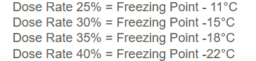
Thanks for that, hadn't thought to check Screwfix. For completeness it would seem this has a pH in the range 7.5 to 8.5 and I eventually found the following dosage table in the Q & A There are other tables here. It says that low concentrations of ethylene glycol (<25%) are at risk of bacterial contamination. I wonder if the biocides you can add to marine diesel would be effective? But they are pretty expensive too. On the whole I would prefer an ethylene glycol based fluid because as you know my application is close to the limits on heat transfer. But I don't want to use a lot of it because I have a relatively mild climate but a large thermal store to fill.
-
No, it seems not. Of those widely stocked by plumbers' merchants Fernox HP-EG is based on ethylene glycol (CH2OH)2 which is highly toxic and has a pH of 7.7 (slightly alkaline). Minimum concentration is 25% for proper inhibition, which protects to -10C Sentinel R600 is based on propylene glycol CH3CH(OH)CH2OH which is much less toxic but more viscous so more difficult to pump. It has a pH of 6.5 (slightly acid, arguably less desirable). 20% concentration will protect down to -10C. In addition specialist companies like Hydratech make several heat transfer fluids based on the above, plus other low viscosity and bio-based liquids. They also make Thermox DTX which is available retail and is an ethylene glycol based fluid with detoxification additive. 22% is needed for protection to -10C. So what do people actually have in their systems and in what concentration? Has anyone got the chart which distinguishes between the temperature a solution becomes impossible to pump and the (lower) actual freezing point for a given concentration? What would be the recommendation for a coastal site in Devon where the lowest temp in the last ten yrs was -4.9C (on 1/3/18)?
-
Low loss headers and plate heat exchangers for air source heat pumps
sharpener replied to dnb's topic in Boffin's Corner
You need to keep the flow temp down to that level for best CoP. So if all flow temps are matched then heating not a big problem - if you can run it with all the UFH engaged. Then you will not need a buffer or LLH, they both involve mixing hence an increase in entropy and so loss of thermodynamic efficiency, Heat Geek call it "distortion". You might not need a volumiser either if the UFH volume is enough for defrosting. There is a good discussion of all these arrangements on the Caleffi website, mostly they are to make the system more bullet-proof for the installer not to benefit the end-user. Avoiding call-backs is a big incentive for installers which is why they over-specify HPs and leave them set ridiculously high. Much of the above discussion seems to be about DHW. My own planned installation has got a secondary circulation pump to improve heat transfer in an existing tank, but starting from scratch it should be easy so keep it simple. As @JohnMo says first select yr size using some rule like 45l/day * {greater of [actual occupancy, # of bedrooms +1]}, specify 3 sqm coil, job done. (Newark will quote for custom configurations inc 2 x immersions and many other options. Ideal cylinders are identical to Gledhill but much cheaper. HP mfrs own cylinders are more expensive again.) PHEs involve an extra temp drop typ. 5C, so much the same as a coil, useful for corner cases but generally offer no advantage over a good coil and will de-stratify which you do not want to happen. I have recently looked at the trade-offs between storing energy as hot water and battery storage here. In summary thermal storage has a payback of 12 - 20 years in which time you are likely to have replaced batteries once or twice which makes them more expensive. In my case I have already got them, they are not big enough to run the HP entirely but will be useful to fill the gaps caused by the sun going in unexpectedly. With your smaller HP this will be easier to do, get the smallest HP you can get away with as then batteries will go that much further and you will need a smaller inverter as well. And it will modulate to lower outputs in mild weather without cycling on and off. IIRC there is an issue with Samsung HPs, they use some trick ?hot gas bypass? to improve turndown ratio but at the expense of efficiency. -
Installing wifi adapter on Ecodan
sharpener replied to Garald's topic in Air Source Heat Pumps (ASHP)
Doubt it. You would have to read the terms of the warranty provided by the original installers. They might not be enforceable anyway. Unfortunately, by asking how much they would charge, you have alerted them to your plans, did they say anything at the time? Otherwise I will leave it to @Kelvin as he has first-hand experience of the process and may be can shed light on the warranty issue as well. -
As upthread the flow setter is planned for the TS branch as that will have almost zero resistance otherwise and steal all the flow. At £51 a time not sure I need a second one on the coil cct as the Arotherm display will show the total anyway. Why on earth do they not use s/s tanks then (like the OSO tank I have got)? Or treat the water.
-
Installing wifi adapter on Ecodan
sharpener replied to Garald's topic in Air Source Heat Pumps (ASHP)
I would give it a go, you are unlikely to damage anything. If the rest of the installation instructions are clear and you feel capable of carrying them out I don't imagine there would be any problem. If you are going to employ an electrician to do it then at best he will have installed one before and it will be a doddle, at worst he will have no more clue that you and you will be paying for his time while he looks it up on youtube just like you could have done. The biggest issue is likely to be not the physical installation but getting it registered on your wifi network, that will depend on what security measures your router has got. How comfortable are you with working on the wifi setup? For comparison I installed a zappi wifi car charger a year ago and it was quite complicated because of the MAC access control and network extender I have got installed but I got there. If I had used an electrician I would have had to explain all this to them anyway because the standard install instructions would not have been much help. -
Thanks for the reminder. In fact I offered them a blanket clause about all pre-existing equipment following the Tech Dir's visit 9 Jan, I had forgotten(!), will mention it when am next in touch (still awaiting 13 Feb visit report). Will also remind them that Vaillant visited back in October and confirmed they were happy with it as it is.
-
Good point. If it is an inverter drive then who knows what the waveform and power factor will be like? OP would be well advised to check that the proposed device measures true rms power not just infer it from the current, the spec here does not say. Fortunately it appears to have an AC voltage connection so at least there is that possibility.
