sharpener
-
Posts
1487 -
Joined
-
Last visited
-
Days Won
1
Everything posted by sharpener
-
I started on this with a quite open mind and of the three installers I got quotes from the front-runner originally proposed a Stiebel Eltron. They too are expensive and the 15kW is an extremely bulky single-fan model which would have taken up a lot of our kitchen yard. They then suggested a 12kW Vaillant which is taller, thinner and can go closer to the wall of the house. So I said yes to that. It has almost as much output but still needed a bit of playing with the MCS calcs. Since then I have put in a lot of time and effort working to get a manufacturer-approved system design which solves a number of technical issues, and ideally I don't want to have to start again with a different brand. Also it would mean re-applying for PP and DNO approval. Mitsubishi would probably be next on my list but a whole new learning experience to get to the same point. As reported here I liked the look of the Grant R290 models on show at the exhibition but they don't seem to be available yet. At the more cheap and cheerful end CoolEnergy look interesting but the form factor is against them. Octopus say I am out of area, Good Energy have quoted for 2 x 12 kW Midea(!) which I do not have room for.
-
South Hams, Devon. Meantime I have seen yr other threads about Alto, but when I contacted them they did not do Vaillant and would not do custom designs. So if you have migrated from an 11kW Ecodan to a 7kW Vaillant I am guessing you have gone with someone else?
-
Brilliant, best of luck with it. Have you discovered this simulator? Now that it seems my Vaillant installer has turned into a pumpkin I would be grateful to know who yr MCS umbrella firm is, I haven't been able to find one that does Vaillant myself. Feel free to PM me with any info or queries if you don't want to post them here.
-
Sounds like you need these Vaillant schematics pp 84-86.pdf, which is an abstract from their big online book. If the zone valves for rads and UFH are wired as shown to the VR71 they are automatically de-energised when DHW is operating so you don't need a 3-port diverter at all, just a 2-port wired to UV1. If there is a consolidated voltage-free call for heat from the rad stats that goes to S6 on the VR71. I still don't quite understand what stage you have got to, you mention an installer but appear to be doing the system design and choosing parts as you go along. What am I missing?
-
This is a Vaillant approved method, I have their official schematics that show it. Tell us @mk1_man what controls you intend to fit, you may not even need the relay. How much of the install are you doing yrself, sounds like quite a lot? BTW a 7kW HP hardly needs 28mm pipe anywhere in the system unless the runs are extremely long.
-
Vaillant Unistor cylinder - or not
sharpener replied to mk1_man's topic in Air Source Heat Pumps (ASHP)
Sorry to learn you have lost the battle against the MCS orthodoxy @mk1_man. -
Vaillant Unistor cylinder - or not
sharpener replied to mk1_man's topic in Air Source Heat Pumps (ASHP)
Well since we have to use them if we want the BUS grant I was agreeably surprised (as I re-started my quest today from the beginning(!)) that MCS has a useful database which lists ?all registered firms in increasing distance from your address, which you can filter by service required, and with links in most cases to the company website. So in an hour I was able to contact five firms and one has already got back to me with a site visit for next week. Original installers appear to have gone to ground completely. -
Vaillant Unistor cylinder - or not
sharpener replied to mk1_man's topic in Air Source Heat Pumps (ASHP)
I have had a quite lengthy interchange with Vaillant tech about retaining an existing cyl on a 12kW installation and at no point have they said it will not modulate on HW, some of the calcs I shared with them explicitly assumed that it will turn down to 6kW (summer mode, no parallel heating of the thermal store). Also there is the Noise Reduction mode you can set to be at the same times as the DHW, you can programme the output to be 40...60% of the full rating, see the charts here. The rest of that thread is also quite relevant to this discussion as the starting point was the Vaillant 200l tank, which has only 1.4m^2 coil but the chart shows is compatible with the 12kW HP. Proportionality would therefore suggest a 7kW unit will go on a 0.75 coil and the OP's solar tank is at least twice that. -
Vaillant Unistor cylinder - or not
sharpener replied to mk1_man's topic in Air Source Heat Pumps (ASHP)
I have twice had put to me the argument "but a subsequent purchaser of the house might". In one case it was as noted to fit a new cylinder and in the other to justify putting radiators in the utility room FGS as well as the kitchen. As I told them, if a subsequent purchaser is going to remove the AGA it is likely to be in the context of a £20k kitchen refit so adding a rad or two is small change. And they might want skirting rads or fancoils in the kickspace under the units, who knows? They tried to argue the utility room was habitable and therefore MCS required it to be heated (we have had some discussion on this and I see it was in yr submission to MCS @JamesPa). -
Vaillant Unistor cylinder - or not
sharpener replied to mk1_man's topic in Air Source Heat Pumps (ASHP)
If the current 240l model listed here on p10 is anything to go by, the two coils in series will handle 30kW which is the same as the HP model on p11. Though it does not state the coil areas directly I imagine a call to Warmflow would quickly elicit it, and maybe an email from them would confirm its suitability. I notice the Warmflow HP models show an external heat exchanger. Perhaps worth discussing with W whether this can be added to yr existing cyl and if it is worthwhile to do so. Anything has to be better than unnecessarily scrapping off kit worth £1000+. Yr installers may not know about the Eco mode either which if you can afford the extra heating time will for sure solve the problem. Also as you say the HP can achieve 75C and can have a programmable offset of as much as 40C between flow temp and DHW target, it is in Installer Settings|Hot Water in this simulator. -
Vaillant Unistor cylinder - or not
sharpener replied to mk1_man's topic in Air Source Heat Pumps (ASHP)
Yes, @mk1_manhas Vaillant, DHW priority by default, they also tell me all space heating circuits are automatically de-energised when any DHW heating is going on so S-plan is fine. If you have only got one heating cct and so no VR70/71 wiring centre you might need to add a £10 relay. To avoid the heating being off for too long there is a programmable max time for DHW, and a programmable lockout period before it will re-start, which OP may find useful esp as he has a big tank and a relatively small HP. -
Vaillant Unistor cylinder - or not
sharpener replied to mk1_man's topic in Air Source Heat Pumps (ASHP)
I doubt any improvement in CoP would repay the capital cost of fitting a new tank if it is not strictly necessary. @JamesPa would I am sure agree (name check in previous post doesn't seem to have worked). -
Vaillant Unistor cylinder - or not
sharpener replied to mk1_man's topic in Air Source Heat Pumps (ASHP)
Vaillant are not very consistent in their advice about coil sizes. However 7 kW is not the biggest o/p so I think you will be OK, and you might not need a new tank at all, see under. IIRC their tanks are made by OSO and it might be cheaper from them. You need 2.9 litre/min to transfer 1 kW with a delta T of 5 deg so 20.3 for 7 kW. In a 22mm Cu pipe this will require a flow of 1.1 m/s which is just over the 1.0 max usually recommended. 1 kW will heat 250 litres at ~3.6 deg/hr so to heat it from 19 to 55C will take yr HP 10/7 = 1.4 hours To improve the CoP while heating DHW you can put a Vaillant into Eco mode where it runs at 50% power so the approach temperature is better but of course it takes twice as long. If you are happy to do this (depending on occupancy and usage pattern) then you could probably get away without changing the tank at all, a normal coil will handle 3.5 kW without difficulty. Alternatively you could do what I am planning, fit a bronze pump on the secondary side to recirculate the water and improve the heat transfer. Or fit an external plate heat exchanger. Either would be a lot cheaper than a new tank. @JamesPa has a spreadsheet which will model all this and perhaps will chip in. BTW for a retrofit you do not need to fit a new 3-port diverter either, existing S-plan 2-port valves work just as well, I have this confirmed by Vaillant tech. -
Alto Energy ASHP spec seems wrong?
sharpener replied to BotusBuild's topic in Air Source Heat Pumps (ASHP)
You might find a tool such as https://heatpunk.co.uk/home a bit easier to use as it is pre-populated with U values and radiator sizes. A bit clunky in places but it gave me similar results to several installer surveys (at least the ones I thought were plausible). -
Alto Energy ASHP spec seems wrong?
sharpener replied to BotusBuild's topic in Air Source Heat Pumps (ASHP)
It seems there are several different Altos out there. They have just turned down my request for rads, UFH and a TS in parallel with the HW tank, saying "I have discussed this with my technical director, and we don't have a heat pump that will permit this type of set up and unfortunately this type of bespoke design isn't something he wants to get involved in." So I am assuming that Mitsubishi don't provide the necessary control options, at least not natively. Still waiting for a final Vaillant quote, which was promised as top of installers' list well before Easter. -
Most HPs work with priority to the HW via a 3-way valve, do your proposed arrangements take account of that? From what you have said so far no obvious need for a buffer.
-
Vaillant AroTherm plus flex connection???
sharpener replied to Myatix's topic in Other Heating Systems
Try this facebook page if you get no joy here. There has been some recent discussion about the changed hoses, mainly bc it is now difficult to get the olives on as well. -
Thanks @JohnMo that is immensely helpful. The immediate takeaway is that over the whole MWT range 30 - 50C the o/p appears to be directly proportional to MWT-20 (so is obviously intended for a room temp of 20C). Also by changing to 150 mm centres and adding 33% in terms of pipe length you only get a 10% increase in o/p. In my case my HP installer has assumed I have 150mm centres (which I somehow doubt) in the 1995 floor in my living room, and come up with a 62 W/sq m heat loading to get a room temp of 18C. Using yr helpful nomogram this equates to a MWT of 37C. However his total of 2522W does not sound enough for a 40.6 sq m room in a stone barn conversion. And to get to 20C when it is freezing outside I will need 10% more, so MWT = 41C (43 if the pipes are actually at 200mm centres). Fortunately I am not reliant on the UFH as I have already added 2 rads to get faster warmup, so using them in addition will I hope push the flow temps back into the region of sensible CoPs. Edit having now read @John Carroll's post I agree about the 20C target but am not convinced we need a higher power than 1.00. For example for the 200mm centres and 30 ... 50C I had written down 29, 43, 60, 75, 90 W/m^2 which is pretty much linear. Is there a theoretical basis for the 1.15, like there is for the 1.3 or whatever applied to rads?
-
Has anyone got a formula for how UFH heat dissipation is related to the circulating water temp? I have found trawling through various websites the following rules of thumb: dissipation should not exceed 100W/m^2 for concrete floors and 75 for wood pipe spacing should be 200 mm for boiler systems, and 150mm for HPs with a flow temp of 35C (this gives 5m and 6.67 metres of pipe/sq m of floor respectively) Volume of water in system is 0.12 litres/m pipe run (which is 0.6 and 0.8 litres/ sq m respectively) Flow rate in l/min should be loop length in m divided by 40. (Combined with the previous result this gives a constant dwell time of 4.8 mins independent of length.) Max length should be 110m for reasonable pressure drop (At the flow rate given above the flow velocity is 0.4m/s and the head required for 110m is about 2.8m) All well and good. A bit of additional info in this thread. But nowhere can I find the flow temp required for a given heat output to the room for typical construction and floor coverings, any ideas?
-
This is a counsel of perfection. Many on here including me have to start from having a property with rads already fitted upstairs, and the upheaval of installing UFH in their place makes it impractical. And as @ProDave says we do not need much heat upstairs, there is no insulation in the bedroom floors so they are 16+ without any heating on. My propossed solution to this is - when the rads are required at the same time as the ground floor UFH - to run them from a 55C thermal store charged up at off-peak rates, while the UFH is supplied at the lower flow temp in real time. The house is long and thin and I don't want all of it heated all of the time. That is if the installer ever gets back to me now that Vaillant have issued their final approved drawings for it.
-
compressor size of Vaillant Arotherm 7kw ?
sharpener replied to Post and beam's topic in Air Source Heat Pumps (ASHP)
AFAIR it is only the 10 and 12 kW that need express PP, the others qualify for deemed PP (unless part of a new build IIRC). -
I think the main reason you need a mixer and pump is to achieve a flow rate within the UFH loop(s) sufficient to distribute the heat evenly along their length. From the heat loss equation point of view it is the volume supplied at the higher temperature that matters as it defines the quantity of heat input, for me the surprising point is how little flow you need. A thermostatic mixer will of course achieve this by closing the inlet so most of the flow to the manifold is what is recirculated from its return pipe.
-
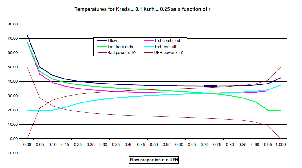
Equations actually result in a figure of less than 20 in these cases which is not physically possible, see my recent post. At the lhs the pnk and green lines do converge though the pink is not that easy to see, soz (the pic is a screenshot of a pdf print of the xls). At the rhs they don't bc I now notice there is a data point missing from the pink line, the missing value at r = 1 is 17.50, same as light blue. This gives an avg temp of 40 to the UFH which is what is required to dissipate twice the design value (2.5kW at 30C). HTH.
-
That is exactly the situation I am trying to model as it corresponds closely to my barn conversion retrofit except the numbers are 6 + 6 kW. I am taking a common feed from the HP to both rads and UFH, at whatever flow temp is necessary to dissipate a total of 5kW (dark blue top line). At r=0 this has to be 72.50(!) to get rid of all the heat via the rads. At the 2.5:2.5 power point it needs to be just under 47C (bc the flow rate through the rads is higher than the design condition so the delta T is less). (At such a low flow rate the equations are actually satisfied by a UFH return temp of about 12C which is clearly not attainable hence I have put in a lower limit of 20. Why this occurs I have not yet worked out, but see below regarding the UFH temp profile. OH teaches maths at Cambridge University and has independently solved the equations in the model to reach the same result but can't shed any light on this.) Have now modelled this too using heat loss proportional to average temp. If s times the flow to the UFH is mixed back from the UFH ret with a pump and mixer then the ratio Tf/Tu is given by 2(s+1) + Ku(2s+1) (2(s+1) - Ku) which tends to 1 + Ku for large s so in this case where Ku = 0.25 (kW/C) the limit is 1.25 If we assume s might be 4 this gives 12.25/9.75 = 50/39 = 1.256 with no recirculation at all k = 0 so Tf/Tu is 2.25/1.75 = 1.286 so not a lot different. But I cannot reconcile this result with the temps from the overall model and I think the problem is the "average temp" heat loss assumption breaks down for the UFH where an exponential decay temp profile along the loop is more likely in RL. Yes of course but in my retrofit situation to get to 45C flow I have already had to re-size the rads by a factor of 1.9x and to match to 30C would require a further 2.5x increase in size!
-
Puzzled by some previous threads about mixing I have run a model of a heating system that combines radiators designed for an average temp of 45C with UFH designed for avg 30C. The model assumes you have an HP which produces 5kW at 5 deg delta T (this keeps the numbers simple), and want 2.5 kW out of each side, as might be the case in a house with UFH downstairs and rads upstairs. The return pipe flows are allowed to mix on the way back to the HP. A few simplifications have been made: the heat loss from the emitters is taken as proportional to the avg temp which is not quite true for the rads, and also at low flow rates the temp drop profile along the UFH loops is not linear but an exponential decay. But I think the general shape of the curves is right and the conclusions are valid. Here is the graph of the various temps as a function of the proportion of the flow going to the UFH. The surprise is that for an equal 2.5kW/2.5kW split you only need 7.6% of the flow to go to the UFH circuit, because its emissivity per degree is much higher and the equilibrium flow temp is also 17 deg higher than it expects. For a 50:50 division in the flow you only get 1/3 of the heat into the radiators and 2/3 goes into the UFH. As you can see, this does not vary a great deal over the whole central portion of the diagram. I don't think the conclusion would be much affected by the conventional UFH arrangement of using a circulating pump and blending valve to temper the actual flow temp to the UFH loop but I have yet to complete the modelling of that arrangement. Notes on the model: It arrives at the equilibrium temperature values by solving the following simultaneous equations (which give rise to some very complicated algebraic expressions in r, Krads and Kufh). (i) The HP produces 5kW at 5 deg delta T - this defines the relationship between flow and (combined) return (ii) Each circuit dissipates an amount of heat equal to the average temp between its inlet and outlet multiplied by a constant K, from which the temp drop across each cct can be calculated (iii) The two circuits together dissipate exactly the 5kW ouput of the heat pump (iv) The combined return temp is the sum of the individual return temps weighted by the respective flow rates (Method of Mixtures).