


MikeSharp01
-
Posts
5693 -
Joined
-
Last visited
-
Days Won
16
Everything posted by MikeSharp01
-

How to calculate heat load…
MikeSharp01 replied to G and J's topic in Energy Efficient & Sustainable Design Concepts
Just ran the free version and it gets close to the PHPP outcome.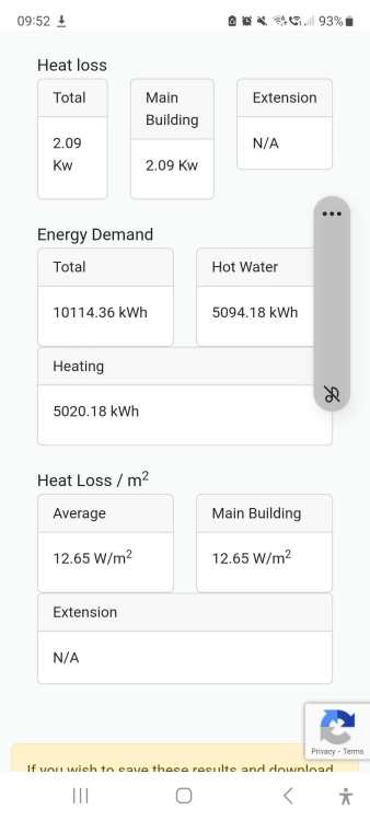
-
How to calculate heat load…
MikeSharp01 replied to G and J's topic in Energy Efficient & Sustainable Design Concepts
Can't tell you what that is because the sheet is locked and its on a hidden row, however by unpacking it (pasting the formulas from the hidden rows into another sheet) I can see it takes more factors into account, there are intermediate rows, than are in the table shown above - so I guess its complicated but it must just, in the end, be some function of the values shown. -
How to calculate heat load…
MikeSharp01 replied to G and J's topic in Energy Efficient & Sustainable Design Concepts
I found this relatively straightforward guide to the difference between heating demand and heating load. https://sustainableengineering.co.nz/qa-with-jason-explain-heating-load-vs-demand/ there is also a discussion here http://public.wookware.org/gbf/newforum/commentsbb9a.html?DiscussionID=13647 on GBF looking at the same issue. Essentially the two values don't have a direct relationship, and you need to know that the Passive House Planning Package (PHPP) & passive house concept generally, has this concept of treated floor area (TFA) which differs from the more traditional floor area - but not significantly for most designs, in ours TFA is 139, and actual is around 150, this is used in PHPP for calculating both Heat Load and Heat Demand but that is where the similarity between the two ends. Heating load is: the number of Watts you need to pour into the house across each square meter of the building's TFA to keep it at set point temperature at the coldest point of the year (it has no time dimension so its an instantaneous thing). In our case this is 8.268W/m2 according the our version of PHPP. Given we have 139m2 of TFA we have therefore need a heating plant capable of delivering: 139 x 8.268 = 1149W or 1.149kW (Which on reflection is bonkers small but that is what PHPP says it is) and as you cannot get a ASHP below 4kW that is the size we we will need. Actuallly in our case, assuming we could get the flow temperature above 42oC space heating via a heat battery in the MVHR would be enough in our case but we have UFH in the slab anyway and will use that. Heating demand is: the total amount of energy required to keep the house at the set point temperature across the whole year, based upon: the average outside air temperature (OAT) each day / week / month (monthly and annual for PHPP) the amount of gains & losses from things like Solar gains (N/S/E/W + Horizontal / Ground) and internal heat gains (people / things / operations - EG Washing up & running the fridge and your mega sound system!) Here is what that looks like for our build in our version of PHPP : So we have will use 1465 kWh/a which comes out at 10.512 kWh(m2a) using the monthly method on our 139m2 TFA given a coefficient of performance (COP) of 3 we will need to pour 488kWh of electricity into our ASHP to keep the house at set point (without cooling - cos PHPP says it won't be a problem, even if I think it will) at 30p a kWh that comes out at £146 pa. Does that clear up the differences for you?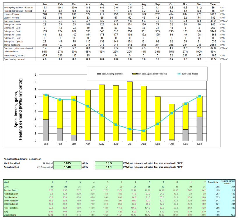
-
Hi and welcome to THE forum for people like us - looking forward to hearing more about the project and getting your input on heating, which is a widely discussed topic on here.
-
Interesting. I have one 'radiator' unit I brought to put in the MVHR supply line to allow heating / cooling but I could get another and make two of these, one for each bedroom!
-
Is this not the very definition of short cycling? Would it be better to run the cooling longer at a higher temperature?
-
So I clearly need to think this through. I cannot run drains as all the pipe runs are in the ceilings so above and supposed unit. Insulated pipe runs not difficult in the ceilings Electricity is no problem - what controls do these things have?
-
Just a temperature & relative humidty (RH) sensor, such as the DHT22.
-
Are you insulating them? What water temperature are you running the FCUs at?
-
We will be cooling the slab at the same time so the dew point will be important. I guess then that some sort of dynamic dew point (DP) monitoring / calculating will be needed as the various environmental factors affecting DP will be moving about all the time. The good old DHT22 in combination with the Lawrence approximation equation [ Td = T - ((100 - RH)/5.) ] should do that? I cannot see how I can do a drain back the plant area given the way the pipe would need to run - so perhaps that is us out of this one, so that's a few grand saved before breakfast.
-
There are many on here that extoll the virtues of fan coil units so I thought it would be fun to see if we could put a couple in - one for each bedroom. Looks straight forward enough but two questions come up. Firstly what pipe to use from the plant space to the units. I have found THIS stuff which looks like it should work. Will it? Secondly do I need to provision for a condensate drain back to the plant room and away or can an evaporative approach be taken as in most fridges?
-
Think the import / export meter should be after the CU so it captures all the loads on the CU not just the inverter / battery combination on the edge of the properties consumption / export.
-
Sealant around sliding doors
MikeSharp01 replied to tokyotecubate's topic in House Extensions & Conservatories
Good plan Either way you still need an external seal, mastic / silicon or compriband (or similar) (I note they say on the section image that this seal is by others but that must be the installers as the drawing is from the manufacturer) and the EPDM under the window needs to be lapped up the rear of the frame, or when fitted the sill, somewhat to prevent water getting in. It is a poor detail in the way it has been done here by the looks of it but we cannot see how it is detailed. The occasional use of a a few packers looks wrong and the continuous sill sounds like a good outcome. Check the registration details of the installers (well the people you are paying) EG FENSA and then consider talking to them about the quality of work as they may well have sanctions they can use if the reinstall is not to your satisfaction. -
Sharing Fee Proposal with other Architect
MikeSharp01 replied to flanagaj's topic in Surveyors & Architects
Then you will need to do a lot of value engineering or borrowing. -
I am no structural engineer but my guess is the three bolt scheme is much better because the extra bolt is taking a chunk of the load and preventing a straight fracture across the two straight up and down bolts - the only thing I really know about structures is that 'triangles' are everything.
-
Don't say that as I only get to build full time in the vacation - then I am back on the semi retired part time role I have.
-
In what way have they declined one wonders, fewer of them, fewer visits by the owners?
-
What is allowed to be left on a building site?
MikeSharp01 replied to Vijay's topic in General Self Build & DIY Discussion
good move - face the daemons head on. -
Nope, no motorways in Norfolk, but not 100 miles to the M11 - the closest I suspect maybe 40 miles. The M11 gets gets you to the bottom of the A11 which is still in Essex - the A11 / A14 bit of the run is good through Cambridgeshire & Suffolk then, when you switch back to the A11 and head for Norwich and into Norfolk, they hit you with a selection of annoyingly busy roundabouts interspersed by some great bits of dual carriageway.
-
We love Norfolk, spent the last couple of days there, going backwards and forwards round the Norwich ring road - one thing we can say is that the diesel is cheap up there, and the pan tiled roof's, the North Norfolk coastal path, big skies only a couple of draw backs- the two lane section of the M11 and the roundabouts on the A11, sort them and it will be even more of a pleasure to visit!
-
+1 I have wired ours as full radial lighting so every light fitting and switch has a wire back to the panel with a number. Appreciate that this cannot be done in this situation but we should move to it, or something equally simple for future builds. The only thing the old approach has going for it is that is probably uses less cable.
-
Sealant around sliding doors
MikeSharp01 replied to tokyotecubate's topic in House Extensions & Conservatories
Would be good to see the outside finish, should be Compriband, might be mastic as @Mr Punter says, post a picture to confirm. -
Welcome to THE forum for people like us, sounds like an interesting project.
-
Sealant around sliding doors
MikeSharp01 replied to tokyotecubate's topic in House Extensions & Conservatories
That looks like Ilbruck air tight sealing foam, they just have not pressed it in flush with the foam. Our installers waited for it to skin then just pushed anything that stuck out back into the gap nothing stuck out. You can probably still do it as the Ilbruck foam stays flexible anyway. You can then run the final plaster board reveals round and plaster from there, assuming that is your build up. -
Just in case I am not happy with my drywalling skills. Did the garden room OK but the house has much bigger expanses and on 10m long wall directly to your left when you come in the front door so you will see any undulations I worry. Base of plaster boards is dead flat and all vertical joints are butt joints with tapered edges - it's just I wanted to be sure I had a get out if I need it.



