RHayes
-
Posts
61 -
Joined
-
Last visited
Everything posted by RHayes
-
@vala I should have @ tagged you to the last to messages and now can't edit them. Let me know your thoughts.
-
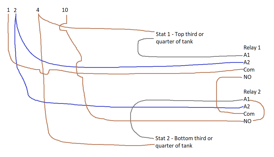
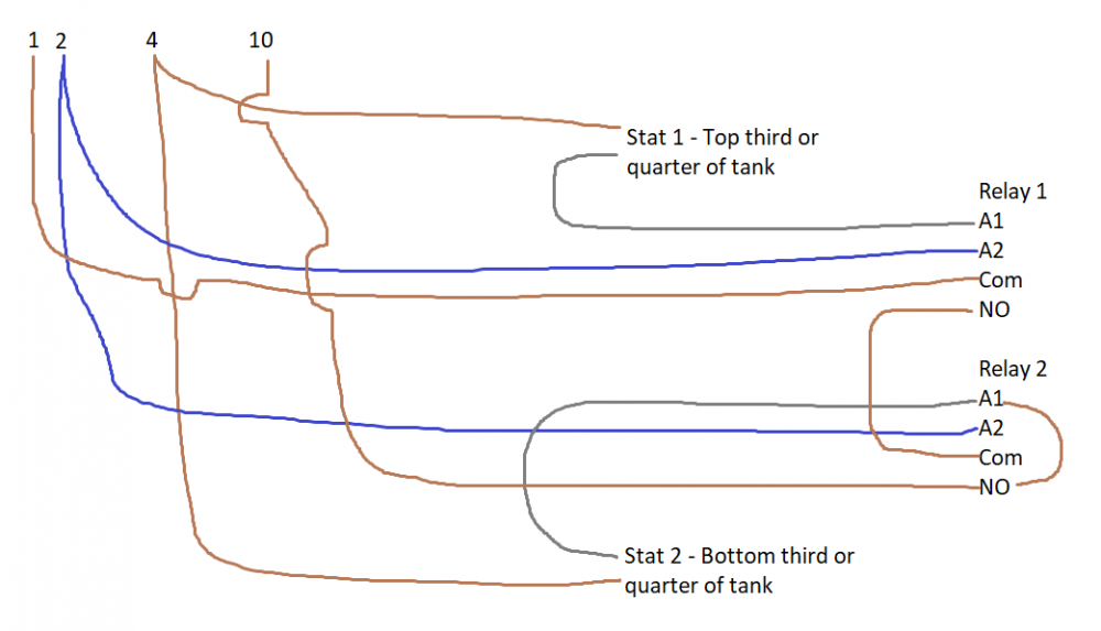
This is a rather rough sketch i have done in paint of how you would connect the stats and relays in the 2 stat option. Trust you can make head or tail of it. It is important that the stats are placed in the tank between the connections to the boiler and the underfloor heating connections. I beleive it is also important that the flow from the boiler enters the top of the tank and return from the bottom. Likewise the underfloor heating is fed from the top of the tank and returns to the bottom.
-
Hello Vala You mentioned in your initial post that you had in mind to get a 100l vessell therefore the difference between the two sensors will be approximately 33 litres. This could always be increased by moving the sensors further apart, for example 1/4 and 3/4 of the tank height. I don't have any experiance in the placement of these sensors, however I guess an influencing factor would be what the output of your boiler is rated at compared to the total load of your underfloor heating. Perhaps you can confirm. We are getting in to thermodynamics and comparing load to demand with different flow temperatures between them too, but assuming it is something like a 30kW boiler and a 20kW underfloor heating load then the boiler will probably cycle on for about 3 or 4 minutes and off for about 5 or 6 minutes. This is assuming the underfloor heating is all but on full demand. If it is only a few areas that are heating then it may be a cycle of more like 1 or 2 minutes and off for about 10 minutes. Not sure that this answers your question, however to reiterate the difference between the two options, with 1 stat you'll have just the 1 controller and sensor. With the 2 stats, you'll have the 2 stats or sensors, 2 relays, and a box to house these relays in. You can buy relays for £8-£10 each (you'd need 2) and an enclosure which i guess could be just a double back box and blank plate to house the relays in. The only extra 1st fix wiring for the 2 stat option is a permanent live and neutral (terminal 1 & 2) to the BS location on the latest schematic and then just a case of connecting them up in the right order.
-
@vala The Thermosense device originaly mentioned by PeterW is the programmer for yhe temperature sensor, be it a thermistor or other type of sensor probe. A dry pocket (or a bit of 10mm copper pipe squashed and soldered at one end as i have done) would be needed to insert the probe in to amd then wire the probe back to programmer/controller for the temperature input. setting the controller to a high histerisis so that the boiler only comes on when the tank drops below 40 degrees and then turns off whenthe tank reaches 60 degrees. This way only one controller is and sensor/thermistor is needed and the wiring is straightforward. If you want to use the principle of two tank stats one at 1/3 and one at 2/3 of tank height then you will need 2 controllers, 2 thermistors and still need the relay set up. In this set up you wouldn't need the 10 degree histeresis and so would just set the bottom contorller at 60 or 70 degrees and the top controller at 40 degrees so that the boiler only ran when needed. there is not realy any difference in this set up whether you go for the original buffer tank stats you were concidering or the Thermosense controllers. I would also guess that the Thermosense controllers and acompanying thermistor/probe is more expensive than the original buffer tank stat you had in mind. I'm happy to do a wiring diagram for you, just need to know whether you'd like to use 1 or 2 points of tempertaure measurment and whether you want to revert to the original buffer tank stat or the Thermosense controller and sensor probe. Trust this helps explain the differences and the benifits of 1 point of measurement or 2 points of measurement at 1/3 and 2/3. LMK your thoughts.
-
Leave the pressure in it. If you do feel the need to take some out then drop it to 3bar but I would definitely not go less. The screed shouldn't make any difference but you want to be able to see or notice straight away if a pipe is damaged whilst screening, with a trowel for example.
-
UFH Just ground or both floors or all radiators
RHayes replied to NewToAllOfThis's topic in Underfloor Heating
Ambiente Systems UK do some low profile systems at as little as 18mm buildup. Is recommended their AmbiSolo. I used this over an existing timber floor and have had excellent performance and response times from it. It's good for your floor finish too as it is a self leveling screed based system and therefore will be flat and will spread the heat out well unlike a groved underlay system. I had to make sure the timber floor was well sealed so that the screed didn't leak to below but otherwise an easy one to install yourself. I only put 50mm EPS insulation underneath too. Partly due to other restrictions but it works well. www.ambienteufh.co.uk -
Routed chipboard should be strong enough for joisted floor providing the routed grooves are laid perpendicular to the direction of the joists. A 3mm ply or even 1.5mm aluminium sheet on top of groved chipboard would be sufficient to prevent feeling the empty grooves. Or just fill the grooves that don't have pipe in with an adhesive, but most grooves will have pipe and this should be flush with the top of the chipboard and won't be felt though the carpet and underlay. Take care on the thermal resistance of your carpet. Kind of goes without saying but a carpet will hold the heat back.
-
Screwing Heatmiser back plates back too tight is a common problem causing the back plate to bend away from the front screen and causing the pins between front and back to loose connection. I'd advise checking that the are just held in place and not wound back in to the wall.
-
Re high points in loops and air locks, I will start off my saying that it isn't ideal, and that the manifold should be at the high point, however I have experience on more than one job where the ideal was not a viable solution and in one case the manifold served the floor above. In one sense this was a physics nightmare, however providing the manifold is oriented so that the loops go down before going up and providing the system is flushed with mains pressure/flow to fully purge with air, then you'll be ok, certainly on a small drop of a couple of steps as is suggested. Indeed in the job I mentioned with the loop going to the floor above providing it was installed and commissioned properly without cutting any corners there shouldn't be any issues with air locks in loops.
-
Just been looking in to latching relays, and as far as I know most of them are designed to run with a pulse input not a continuous voltage. It may be easier to use a couple of SPDT relays and wire them in such a way that it acts as a latching relay this way you don't have the issue of constant voltage on the coil of the latching relay. I can do a diagram on this tomorrow if it helps.
-
@OldSpot Yes a good idea. How has you thought this would wire up with the 2 buffer stats? I am not sure your wider histeresis would work with just 2 standard stats and no other components. On way I can think of is to have a couple of relays connected in a way that would hold one on when you are heating inbetween the two stats, but you may have other ideas.
-
I do just the same. Yep, looks good to me. I'm not sure what a Tado extension hub does. From checking up a little I assume it is a wireless rerceiver for tado controls. If that is the case and assuming you are taking out the Tado controls and puting in Wunda then this extension hub will no longer be needed. I may be wrong here.
-
Air source heating, how far does it run in a loop?
RHayes replied to saveasteading's topic in Underfloor Heating
I was thinking of a contractor but there are some who will do a pre order design for you asking them to do this for you (cheekily or otherwise) woudn't be a bad idea. That way you'd know your pump duties and maximum loop lengths instead of it being guess work, that is if the designer you choose gives you pump duties. Some do and some don't. Look up underfloor heating designers, there is a few uk based who may be able to help out as a one off, but I doubt they'd do it FOC. http://www.ufhcaddesigns.co.uk/ https://www.ufht.co.uk/ -
Youll need a dense shallow insulation as you don't want to redcue that 2.4m any more than you have to. Id recomend something like a 6 or 12mm insulated tile backer board, something like this, https://www.wickes.co.uk/Prowarm-Backer-Pro-Insulation-Board-Single---1200mm-X-600mm-X-6mm/p/166935. You'll need to put a self leveling or laytex screed over this to encase the electric cables and provide something flat and firm for the lino to be adhered to. Remember to put the floor sensor in the correct place before you put the self leveling screed down. Key things to be aware of, the electric mat will need to be encased or covered by a screed or cement based materials with no air gaps. Any air gaps will limit the heat conduction away from the electric heater cable and may mean the electric heater cable over heats and trips out. The insulation will need to be firm as the depth of screed is going to be so small.
-
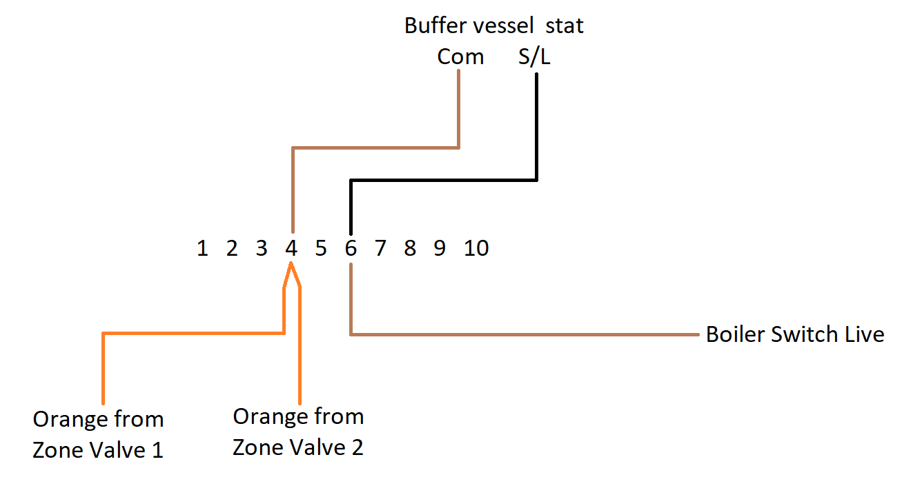
On that diagram: 1 is permanent live 2 is Neutral 3 is Earth 10 is switched live to the boiler (shoudl be from the zone valve orange only) You also need switch lives for the following (which you can use any of the other spare terminals for. Switch live from the Wunda wiring centre to the buffer stat Switch live from the buffer stat to the zone valve (brown) or directly to the boiler (terminal 10) if you aren't using the zone valve.
-
Whilst the colour is blue this isn't neutral. This is switched live as mentioned in Vala's earlier post (Brown goes to Com and blue goes from 1). Strictly the blue shoudl be intalled with brown sleaving to indicate that is has 230v live on it.
-
Some amendments are required to this diagram as wiring it like this will mean the boiler will maintain a hot buffer tank over the summer. I'll start with the BS (assumed to be buffer stat). The brown wire to BS needs to be connected to the blue from the Wunda wiring centre that is currently wired in to 10. Thererfore you need to use a separate terminal (4 for example) to connect these 2 together. If you don't use the zone valve as mentioned in my earlier post then this is all you need to do. If you are going to use the zone valve then the brown from the zone vavle will need to connect to the blue from the BS (buffer stat). The reason the above diagram is not correct is that you have the wiring centre, the buffer stat and the zone valve potentially all asking the boiler to fire, however only one item shoudl be connected to the boiler directly and everything else should switch in sequence up to that point. Trust this helps.
-
Yes. You don't need a zone valve in this system. Zone valves are to stop the flow of water to a part of the heating system when the system pump or main circulator is running for another element of the heating system. In your system you have basically substituted all the zone valves for pumps instead. There is a pump that will circulate from boiler to buffer and nothing else. There is then a pump that will circulate from buffer to ground floor manifold (nothing else) and a pump that will circualte from buffer to first floor manifold (nothing else). Therefore as all pumps are only circulating one part of the system each and not affecting the other parts, this effectively negate the need for any zone valves.
-
Air source heating, how far does it run in a loop?
RHayes replied to saveasteading's topic in Underfloor Heating
I haven't heard of a 50m maximum before, but as Olf mentiones it is down to internal pipe size, and number of bends etc. that contributes to pump duty. The only reason the pipe work lengths are limited is to prevent having to have too big a pump, or having too high a flow rate requirement. Typically a 16mm UFH pipe system will be quite happy with loops of 100m. We use 17mm pipe ourselves and have a maximum of 120m as rule of thumb. Have you had a UFH design done for the property. This would be the best way of getting the pipe runs calculated and working out flow rates, pressure drops and ultimatly circulator pump sizing. -
This is likely to be 15mm being jg-speedfit Ambiente UFH, based in Hatfield, Hertfordshire hold cliprail in stock with adhesive backing and no barbs. It is strictkly for 17mm but i know it is tight for that size of pipe and i expect 16mm will be fine. - www.ambienteufh.co.uk
-
To answer your original question I would measure 100mm out from the wall, or finish wall if possible to gauge where that will be. As another mentioned 200mm is quite satisfactory too, or anywhere inbetween. The reason for this is so that you avoid coving the pipe with the final buidup of the wall, or hit the pipe with carpet griper (I'd still glue these anyway) or anything else that is up against the wall, e.g. skirting. In otherwords it is to give you the perimeter around the edge to avoid pipes conflicting with structure and any fixings and heat isn't needed any closer than that, especially on a screeded floor as the screed spreads the heat out the best.
-
Typically I would recomend puting in zone valves before underfloor heaing manifolds as it helps extend the life of the actuators on the manifold (prevents let by), however in this system as we only have the manifold/mixing pump sets and no other pump between the buffer tank and manifold there isn't really the need, it is just another component to go wrong, (and there is one particular make of zone valves that is notorious for that). As PeterW has confirmed, wire 1 and 10 on the S plan wiring centre to 1 and 2 on the Wunda wiring centre. Then from 10 in the S plan will need to go to the buffer tank stat and then on to the boiler switch live. I think you mentioned that the boiler is a combi so no need for any zone valves. If there is a timer at the boiler or buffer then I'd also advise putting these on constant and let the control be from the Wunda thermostats, otherwise you will be depending on both timers being on to get any heat.
-
I have to confess I did read the drawing incorrectly. My diagram should have been to terminal 10 instead of 4 to match the S plan diagram. You will only have 1 S plan wiring centre and the two underfloor heating manifolds would connect in to it. One as shown above, in terminals 1 and 9, and the other one in to 1 and 5 (in place of the radiator stat). The hot water part (terminals 6 & 8) is not needed. An S plan wiring centre is simply a fancy name for a multi terminal junction box as far as I am aware. The terminalso 1 to 10 are simply means of joining the right wires together and the numbers are to make it easy for anyone to do. It doesn't matter which number of terminal you use for what. so long as the correct wires are joined so as to follow the switching sequence. I call it a switching sequence as the flow of 230v power (demand) has to go through the right components and in the righ order. A convential system would be Power supplied from the consumer unit/spur, to timer, on to thermostat, on to valve, on to boiler and/or pump. Therefore the switching sequence is time control, temperature control, open the valve, then run the boiler/pump. As you say you don't have the hot water part of the above diagram and the thermostats are wireless, (although if you have the option to run wires in (I strongly recomend it) and go for a wired thermostat then you won't have to change batteries and won't be depending on the weak RF signal from them.) therefore the power goes to the Wunda wiring centre. (This then switches its own local pump at the manifold). You then have the demand live coming from the wiring centre to the zone valve (Brown). The Grey on the zone valve is permanent live and the orange becomes a switch live to the buffer stat, which is then passed on to the boiler if the buffer is not warm enough. Hope this helps explain and simplify the 'S plan wiring centre' or 'fancy junction box.
-
Ok, so terminal 4 on the S plan wiring diagram above is ultimatly the call for heat from your underfloor heating and in the fulness of time I assume you'll have 2 zone valves wired in to this, ground and first floor UFH. Then from terminal 4, this needs to go do the buffer vessel stat, then from the buffer vessel stat on to the boiler. This is the basics of it, see below.

-
I'm guessing that you have an S plan system currently, right? If you are planning on haveing underfloorh heating throughout with the Wunda wiring centres, (and by the way one thing that has been left off your drawing is any thermostats and the cable runs from them to the Wunda wiring centre) and as there isn't a direc link to the boiler (boiler simply maintains the buffer temperture) then there isn't a need for an S plan wiring centre. That said, how is your hot water heated?