markocosic
-
Posts
979 -
Joined
-
Last visited
-
Days Won
1
Everything posted by markocosic
-
It is fine. A surveyor will be sent. The surveyor needs to see a stop tap in the street and a stop tap in the house. Photos are needed for the form / app to raise the job. The meter fitter needs to see a pipe in the trench connected to the meter. Photos are needed for the form / app to close the job. The form / app doesn't ask for photos showing that said pipe in trench is indeed connected to said stop tap in the house. It is very much in the interests of the men with the meters and shovels wanting to close the job to assume this though. 😉 Happy aligned pragmatic incentives. 🙂
-
How to control an Ecodan with UFH manifolds?
markocosic replied to ADringer's topic in Air Source Heat Pumps (ASHP)
Ditch the separate UFH pumps? Feed the while lot directly fed from a big pump at the heat pump. Run the whole lot on the heat pump controller weather compensated. Room thermostats can still "trim" hot rooms down (locally "call for no heat" as it were" but for the most part do nothing because your output is limited by the weather comp and they stay open. -
Weight of insulation may also be an issue - how much can these structures take?
-
Batts from the side. Fit membrane in ~1 metre wide strips that it comes in. Post insulation in from the side. As you go along. If you start from both ends and meet in the middle then you can probably arrange it, with mineral wool batts, such that there's half a metre of batt overhanging in each side before you put the final metre of membrane up underneath. Is still be a little concerned about air pressure on windy days with a big door open sucking/pushing against this insulation though. 2" of spray foam is probably enough. U value 9,000 down to U value 0.5 and perfect airtightness. £15k for materials and a month of misery saved seems good value to me. £300/month over 5 years even if borrowed?
-
Go to America (via YouTube) for big cheap buildings. You either spray foam these structures (cheap) OR you effectively build an insulated inner wall and hack ventilation holes into the walls / ridge such that the tin is just a ventilated rainscreen (expensive). With a hiding hole that's properly heated/cooled with an A2A unit for defrosting between jobs. IMO paint booths should be an internal space partitioned off from the rest so that you can keep the grinding/welding shite and pigeon shite away. Air feed your mask with fresh air rather than using a 3 foot fan to impart a texture finish of bugs and dirt onto the car. 😉 Heat that BEFORE the paint job and AFTER the paint has tacked frankly with fan heaters. Cars stay warm for some time. Don't leave the paint tins in there when doing this. Definitely don't leave the dinitrol tins in there whilst doing this. Worst mess ever. Except for that bloke whose cat ran into the garage, got blasted with waxoyl and knocked over the lamp whilst running back into the house with the beige carpets... (ex Land Rover and MX5 owner here...) Between those Z-purlins you have 5 bays to span ~6 metres (plan view) or ~8 metres (roof diagonal) They are not so big. You want some ventilation above the insulation to clear any moisture that does live there. You don't care for a flat ceiling. Are roofing membranes fire retarding? Wrap one end around a piece of wood (a couple of times) and staple to the wood. Attach this wooden batten to the Z-purlin at one eave using self drilling tek screws that'll whizz through wood then self drill into the purlin. Repeat for other purlins keeping it taut. (perhaps Wrap over a round bar clamped to the purlin at the ridge with some small spacers (so that you can pull the thing tight) and another round bar clamped to the purlin at the opposite eave. Hang weights / pull tight. Tek screw it to every purlin using battens to clamp it.) Insert 1200 mm batts of mineral wool on top of the membrane (with a couple of squirts of foam to hold hem to the membrane in case it tears for some reason and you avoid these falling on your head) between the purlins leaving a gap above to the roof. Repeat down the length of the building. Curse at the last 1200 mm? Or do the same with chicken wire held up to the purlins with battens and mineral wool above. That'll never burn. Your steel will be ok if there's enough airflow in the air gap above. Blast it with white emulsion for lighting. Pop a piece of plasterboard down the ridgeline for lights. Pop two more strips at the eaves for lights?
-
There is your bypass. The upstairs rads have shut down their TRVs. All the flow is whipping straight through the towel rail and back to the boiler at 65C with no heat being rejected to the rooms upstairs. (If the rads were chucking out heat the return water would be cooler) The UFH on the other hand IS drawing heat from the boiler. Can't say where it's going if you've got adequate insulation. Probably no showstoppers just death by 101 issues. Temperature control on boiler would be: - Fit 3rd party Opentherm capable thermostat / time clock/ programmer that tells it to use X degC when on the CH zone and Y degC when on the HW zone - Fit OEM weather comp controls - this mentions where the DHW call for heat must be wired so that the boiler runs at higher temp not weather comp temp when the HW zone is calling: https://www.baxi.co.uk/trade/boilers-parts-and-accessories/-/media/websites/baxiuk/sagittarius/trade-section/files/boiler-controls/7225851-multifit-relay-outdoor-sensor-kit.pdf?la=en&hash=D7E47402B2188AE578FCEB1FF0BC0DCFC86AB6CF That may need a replumb of your zoning though. Alternatively redo the lot with a heat pump and chuck the boiler in the bin whilst at it!
-
The boiler SHOULD modulate down to meet your flow temperature setpoint. If it can't modulate down enough then it will shut off until the circulating water has cooled sufficiently that it can fire again. That is not necessarily a disaster. (old boiler never modulated at all, and relied on cycling to match their average output to what is needed) It will still operate with acceptable efficiency if the flow/return temps are in the condensing range. Your radiator output is not high enough to be above the boiler's minimum output. That's probably because your rooms are at the temperatures (that are set by the TRVs), the TRVs are throttling the input into the radiators, and something somewhere is bypassing the flow back to the boiler return in order for it to be this high. If you have a towel rail on the circuit that would be a likely culprit. Else look for a sneaky bypass hidden somewhere. Setup the boiler properly. Space heating should be weather-compensated (flow temperature out to radiators only increases if it needs to because the weather is cool). This should result in the TRVs throttling the input into the radiators less. Better for it to sit there condensing at 45/40 than not condensing at 70/65. If you can't weather-compensate the boiler because it's been installed by some numpty as a non condensing boiler then you'll need to rework your controls such that the hot water cylinder and the space heating systems can operate independently/request different flow temperatures from the boiler. It sounds like your underfloor circuit IS drawing enough water / heat from the boiler that the return remains tolerably low. (i.e. all 30 degrees is being sucked out by the floor) If it ALWAYS runs like this then your underfloor system must ALWAYS be calling for heat and NEVER reaching setpoint. The UFH mixing temperature should be set as high as the floor can tolerate/as high as the floor needs to deliver the peak space heating demand in winter. (whichever is less) You can then use the weather compensation on the boiler to reduce the flow temperature out to the floor to less than this if you don't need that much heat. The above will trim your usage by perhaps 20% by allowing the boiler to condensate and reducing cycling time by having more of the water in the system active at any one time (rather than throttled by TRVs) Fundamentally your energy use is what it is due to the building fabric / ventilation / comfort setpoints rather than the heat source though. Is there adequate insulation under this UFH or are you now "slowly reheating the ground under the house" after a summer of inactivity and it slowly getting grained down over autumn? That could also be an issue. A floor that manages to keep on sucking heat out from a boiler is suspect.
-
A friend of mine has just bought a house. The original house is 1920s with a side extension by Handy Andy in the 00s. The floorboards on the ground floor are coming up as we speak for rewire / replumb / insulation. Boundary stop tap is in the footpath outside the front gate; approx 0.5-0.75m from the property boundary. Incoming water pipe is steel. Indoor stop tap in the kitchen. No water meter. Current floor is wooden boards on joists on dwarf walls with concrete oversite. It'll probably get the dwarf walls knocking out, 300-500 mm of EPS in the hole, and a sand/cement screed when it goes back down. We think there's a leak between the stop tap in the footpath and the house. With stop tap in the footpath open you can "hear water" with the sound coming from the incoming water pipe - whether the indoor stop tap is open or closed - at all times of day/night. It's about 20 metres as the crow flies from the stop tap in the footpath to the incoming water pipe. Q1) Does that sound like a leak to you? Or is it possible that with the stop tap open you hear water fro the mains rushing past to other houses? Affinity Water offer free leak detection services...but only if you have a meter fitted. Q2) He doesn't want to touch this ever again. A plastic pipe from the meter to a stop tap inside the house would be ideal. What's the most appropriate approach / phasing? We were thinking: Indoors: - Drop 25 mm EPS on top of the concrete oversite (to cover any sharp bits) - Run MDPE from the final inside location (at rear of property in kitchen) across the top of this, clipped in a straight line, then out through the front wall of the property into a hole outside the house, and left in a coil for now - DPM over that EPS and cut/taped around the incoming MDPE (and potentially existing incoming electricity supply that he's yet to expose) - Main EPS floor insulation, secondary "DPM" to stop the screed floating the insulation when laid, then pipework / cabling / screed Outdoors: - Trench to the footpath, unroll MDPE, ask for a meter to be fitted and hook up the MDPE at the same time to avoid needing to dig up the footpath or having joints on the consumer side of the meter. or - Trench to the footpath, unroll MDPE, ask for a meter to be fitted to the existing steel supply, then hook up the MDPE whilst whistling Potential issues: A neighbour had a replacement supply pipe fitted. Affinity Water refused to connect without "certification" from a professional that it met some requirements about how it enters / type of stop tap etc. Probably these: https://www.affinitywater.co.uk/alerts/lead-pipe-replacement/lead-supply-pipe I think these are the same but clearer: https://www.nwl.co.uk/globalassets/customer-pdfs/wholesale-pdfs/laying_new_water_supply_pipes_2018.pdf Involving burying this kind of thing: https://www.murdockbuildersmerchants.com/110mm-90-degree-long-radius-ducting-bend-ud471 https://www.murdockbuildersmerchants.com/110mm-single-socket-ducting-pipe-60m-ud460 That duct with a 750 mm radius exiting 750 mm below ground level would be a kango hammering ditch digging footing disrupting pain in the backside. The cold water pipe would then need to be trenched all the way around the house. This is (1) digging 35 metres rather than 10 metres and (2) would mean digging this in a side alley and I suspect digging below the footings of the Handy Andy side extension (tops are visible 400 mm below ground level) which he isn't took keen on vs taking the pipe through the front wall and under the floor. What we're proposing would have the pipe ~600 mm below finished floor level; shoved through a ~75 mm hole drilled at a downward angle through the outside wall and packed with stainless scourers to end up ~600 mm below ground level outside and dipping quickly to 750-850 mm below ground level for the run to the stop tap before rising up again to ~500 mm below ground level. (which is where the stop tap is...) Is this a stupid idea? The folks that you're allowed to talk to as a consumer aren't interested in informal advice. You'd have to notify to get a decision and at that point...you've notified and are kinda bound by that decision. https://www.affinitywater.co.uk/metering/water-fittings-regulations-notify We haven't found the existing entry point yet (pipe enters kitchen floor void horizontally before kicking up in the corner) but based on where the stop tap is in the street / electricity cutout is / gas meter has been moved to we think the water pipe might have entered where Handy Andy built the extension and suspect if there is a leak it'll be where they might have whacked the pipe with a digger / concreted it into a footing that moved.
-
Is this a house or a flat? Private or ex local authority? If that is a heat interface unit on a district heating scheme do be aware that some run at decent (e.g. 10 bar static) pressure and temperature (e.g. 95C) - be careful.
-
At least a week for a rat IME. They take an age to dry out and stop stinking. 😕
-
Though the OSB too? 😮 There's no stopping the things 😕
-
She doesn't make / post doors @janette Too much heartache involved in ordering the doors themselves and you don't want to be the one to "sell the door" and therefore be the one to warrant all the door mechanisms etc. If you had a door already (with a "weatherproof" painted finish already) she could probably key/prime this and apply the same kind of finish to it; which would be as durable as the varnish/lacquer applied over the top. Door would need to be demounted for this though as you can't work the finish vertically. Quite the faff to arrange during a build. Not so bad as an addon in spring/summer later though.
-
Demand controlled recirc/purge
markocosic replied to markocosic's topic in Boilers & Hot Water Tanks
Nothing specific in mind - it just seemed such a simple solution to existing setups that there must be a catch. Cooler water would recirculate back towards the unvented cylinder/expansion vessel before being sucked back towards the fixture to blend with the hot. What's the UK logic for prohibiting it? Risk is...? -
Hot water recirculation is nice but (can be) wasteful. You could recirculate only when there is presence detected. That's nice. Any tried tested and recommended presence sensors for (a) whole bathroom or (b) right next to kitchen sink? You could recirculate right back to the cold feed to the tank. You could also backfeed the cold water line near the fixture back towards the tank. See the last bit of this YouTube. Is that legal under UK regs? @Nickfromwales? It look neat to avoid an unnecessary return line; at the expense of your cold water being lukewarm afterwards. This also worth a read: https://www.garykleinassociates.com/PDFs/15 - Efficient Hot-Water Piping-JLC.pdf
-
Size. 1 ACH in a shoebox is a lot less fresh air than 1 ACH in a warehouse. A fixed amount of CO2 fills a shoebox faster than a warehouse. Passivhaus projects tend to be high end. High end projects are bigger. They set the ACH based on an assumed "stocking density" of humans per cubic metre. If the density is higher the ACH need to be higher.
-
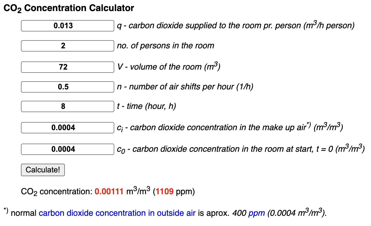
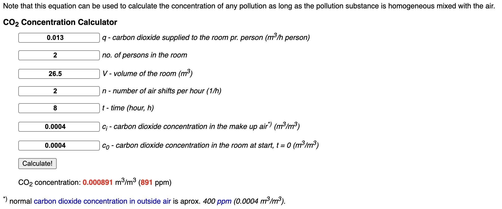
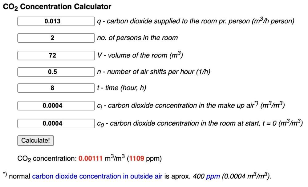
Sze. Passivhaus builds tend to be decently sized. 0.5 ACH works fine for out LT apartment: (double bedroom 6 x 4 x 3 metres = 72 m3) That's the equivalent of 1.35 ACH in a 26.5 m3 room AND you've got that much more volume to dilute into over the 8 hour period.
-
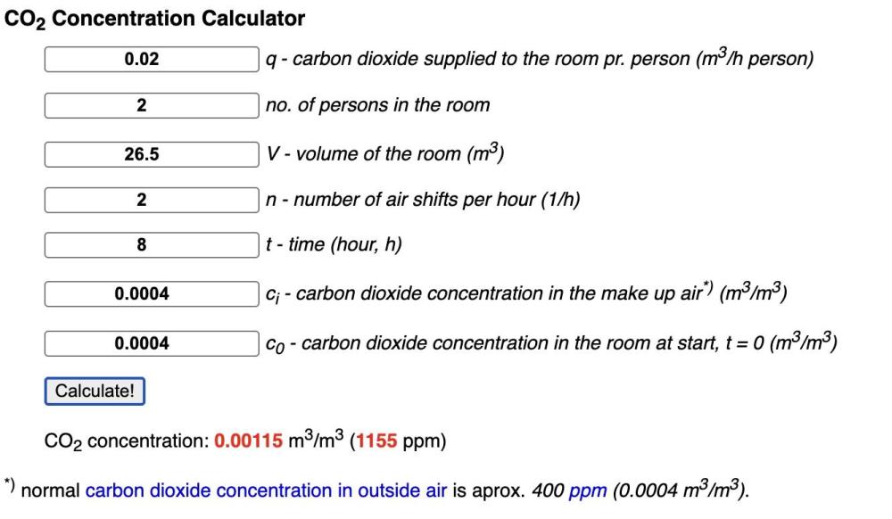
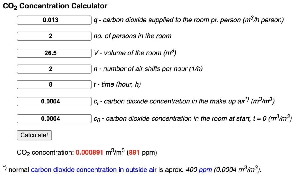
I'm not sure @Marvin It isn't something that I've given too much thought to previously; but now that window closed season is here and I have a lodger that I didn't have before so the door is shut; it's something that needs attention. Drivers for airflow are: - Moisture removal - CO2 removal - Heat transfer Bedroom 1 is 3.2 x 3.6 x 2.3 metres. 26.5 m3 (small) Bedroom 2 is 3.2 x 2.6 x 2.3 metres. 19 m3 (smaller) Bedroom 3 is 2.3 x 1.8 x 2.3 metres. 9.5 m3 (harry potter) I think CO2 is the annoying one. My wife is more sensitive to it than I am. There's an app for that: https://www.engineeringtoolbox.com/pollution-concentration-rooms-d_692.html So we need 2.5 air changes per hour in the largest of the bedrooms to keep CO2 to 2000 ppm or 6 air changes per hour to keep it to 1000 ppm. 2.5 * 26.5 = ~65 m3/hr or ~1.1 m3/minute or 18 L/sec 6 * 26.5 = ~160 m3/hr or ~2.5 m3/minute or 45L/sec This suggests an "occupancy method" of 20 cubic feet per minute per person or 0.55 m3/minute per person: https://continentalfan.com/general-ventilation-how-much-airflow-do-we-need-to-ventilate/ That pretty much tallies with the 2.5 ACH for two people above. And fits with this reference to 10L/sec per person for commercial buildings. https://assets.publishing.service.gov.uk/government/uploads/system/uploads/attachment_data/file/945754/S0973_Ventilation_Actions_Summary_16122020_V2.pdf Sleeping...probably involves less CO2...so a ventilation rate that gives 2000 ppm for active duty would give 1000 ppm for sleeping duty. There's a page for that too: https://www.engineeringtoolbox.com/co2-persons-d_691.html Sleeping should be 0.013 to 0.02 per person not 0.05 which gives about 2 ACH or 15 Litres/sec or 0.9 m3/min or 54 m3/hr per double bedroom: That's...quite a lot MVHR is this: https://www.titon.com/uk/products/hrv-2-q-plus/ So likely needs to run at 40-50% overnight if serving just the upstairs bedrooms. (which it is) In answer to the door grille: 15 litres/sec. One and a half paint buckets. If door gap 0.8 metres wide and 0.01 metres tall area is 0.008 m2 so velocity for 0.015 m3/sec would be 2 m/sec or so. Breezy! Is my maths right here? Top and sides leaking a bit (depending on how badly the door fits) will add a fair bit more as length is longer. 2 cm door undercut brings that to 1 m/sec Or you trick of leaving off the top door stop bead and having 1 below / 1 above. Assuming forced fresh air input to drive that air change. More Google sanity checking. Yanks use forced air heating/cooling so they need a return air path for the heating/cooling air. (which presumably means fewer concerns on CO2 as if the heating/cooling flow is adequate the CO2 should work out too) https://www.energyvanguard.com/blog/can-door-undercuts-work-as-return-air-pathways/ https://www.energyvanguard.com/blog/easy-retrofit-return-air-bedrooms Talking similar orders of magnitude. 2 cm off the bottom of the doors...or a 20 cfm / 15L/sec / 0.5 m3/hr grille with a decent pressure drop.


-
Any recommendations for air transfer grilles above doors that are light blocking/ sound deadening/suitable for 63 mm CLS and plasterboard stud walls? I've decided that the bedrooms are not well with coupled to the hall for the mvhr to be happy without there being a sock to hang the door open. 🙂
-
We can't tell Jack from their published dataset. Naff all detail on full or part load performance is published. I don't think you do this if you have something to brag about. I think you do this if ambiguity suits you. So waiting on some actual numbers for the RED units before giving a verdict. @dpmiller
-
BBC "Wood in Finnish Construction" programme
markocosic replied to Ferdinand's topic in General Self Build & DIY Discussion
There's a rat in my attic in Cambridge. Stupid cold roof. Stupid cushy insulation exposed to rodents. Stupid cavity wall ladders for rodents. Stupid terraced houses with a slumlord HMO 2 doors down. Stupid room in roof with no eaves access. Bloody smart rat that eats at number 45 and sleeps above number 41 where it's quietest. Bloody smart rat that evades all forms of trap and poison. Took weeks to get the first one with a glue trap posted through a socket cutout. Any new build for me gets a sealed construction inside and out! -
BBC "Wood in Finnish Construction" programme
markocosic replied to Ferdinand's topic in General Self Build & DIY Discussion
Fancy plasterboard. https://inspectapedia.com/structure/Gyp_Rock_Sheathing.php Fires don't like it. Bugs don't like it. Helpful in wildfire and bug country. I wish I had known about it - I'd have cut in diagonals for bracing, then used this outside the timber frame THEN stuffed in insulation at our leisure THEN done the airtightness layer. And not worried about the effing bugs that effing eat their way through the breathable membrane that we did throw over the timber frame; or the effing pine marten that effing decided to shred it's way through the membrane and into the insulation to overwinter. I think this is the same kind of thing and can sit outside for 6 months until the cladding is fitted: https://www.british-gypsum.com/products/board-products/glasroc-x-sheathing-board-125mm#technical-description -
RED are trying to compensate for misguided desire to some a system / general inability to design / balance a space heating circuit by using a very American style pumped zone setup then speed controlling the pumps to set the deltaT. You can do pretty much exactly the same thing with any other heat pump if you swap the inbuilt pump for a spool piece and ensure that your minimum zone flow exceeds that of the heat pump. Pointless though. Just do the pipes and valves right on the space heating circuit...
-
To multisplit or not to multisplit
markocosic replied to Radian's topic in Air Source Heat Pumps (ASHP)
Vacuum / hose out the dust and wildlife; job done. Units used for getting that condense on the outdoor coils stay a little cleaner. Single outdoor unit to single head more efficient and flexible at expense of clutter. -
Liquid injection to run the compressor harder without melting it or trashing the oil/refrigerant is the party trick. Doesn't do much for performance in the normal range AFAIK. Figures for the 8kW unit vs some for an Ecodan and an R290 Vaillant Arotherm. (these show part load, Samsung doesn't) sCOP 4.6 on the 35C cycle and 3.4 on the 55C cycle. It ain't 5+. Key features: (1) is black (nice) (2) capable of running hotter than you need to for idiots that want hot water over 50C (meh) (3) capable of maintaining output at decently low temperatures for use in real winters (main application) You won't be able to use it for space heating at high temperatures without murderous COP. The idea that you retrofit to old radiators is stupid but that's exactly how the marketing people are going to ensure installations are effed up along with official instructions that tell you to use a 4-pipe buffer vessel to maximise the temperature that the thing here to run at. The sCOP at regular temperatures is good but nothing groundbreaking. No published part load data so we can't tell how it's really going to perform yet. Uses yesteryear refrigerant but looks to be a generally nice unit even if it is still using legacy refrigerant. Register for Samsung partner portal.for what data there is - no technical limitations to stop anybody doing this even if the official launch has been delayed. Not all the performance data is there yet though. If you want a *really* tasty unit...I'd buy something else. €12k but makes sense if your heat load is large enough. https://lambda-wp.at/luft/ Air to water unit. High efficiency courtesy of R290 (propane) refrigerant AND hulking great heat exchangers. Seasonal COP of 5.7 on the 35C cycle / 4.6 on the 55C cycle in medium climate. (UK is warm climate so should be better) Rated capacity is down to -10C. Can run up to 70C if required. Quiet courtesy of blowing through the heat exchanger to muffle fan noise rather than sucking through it and giving you direct fan noise. Three options for PV diversion 1) run at a set output when digital contact bridged 2) measure the actual excess export and run at as close to this as possible using a meter 3) get told what to run by an external device using a modbus input Also tall to avoid getting buried in snow; buried in cold lakes of air; and designed to thermosyphon from the house in the case of a power cut so needs no antifreeze.

-
What energy rating is your HW cylinder?
markocosic replied to Adsibob's topic in Boilers & Hot Water Tanks
And the share of bought in vs generated electricity. I think you're generous with PV on two counts - Probably generates less than 1000 kWh per kW(p) per year - Seasonality is all wrong so you'll waste loads in summer and not have enough in winter (when the water also needs more heating - try 5-20C variation) Try a seasonal calc using pvgis and variable temperature and I think you'll conclude that you need a lot more than 3kW(p) to supply that kind of demand.