markharro
-
Posts
638 -
Joined
-
Last visited
Everything posted by markharro
-
Thanks for the advice. Turns out that the the lights we have are fire rated. Another connected issue though. Our electrician has wired one of our shower room switches to power a downlight and an LED strip. The LED will I think be 24V so will need a driver and the downlight is mains voltage. I called the manufacturer of the downlight and they recommended not to use it with the low voltage LED strip. So do I need a 24V downlight for these to work properly together? If so any links to a decent IP65 and fire rated 24V downlight?
-
Can anyone recommend? We will probably only fit 5-6 recessed downlights in the whole house but seem to recall building control had specified need to use these hoods if installing in insulation as will be as the GF/FF ceiling void will have 100mm acoustic insulation. Thanks.
-
Wetroom Tiled areas - plasterboard or backerboard?
markharro replied to Conor's topic in Bathrooms, Ensuites & Wetrooms
I have installed Hardie backer for our shower enclosure but for the rest of the room I won't need to use this but the question is what is normally used? Moisture resistant plasterboard? We indeed to lime plaster whatever we use if that is relevant and the board will extend to within about 3mm of the (concrete) floor as a shadow gap. Also do you need to use moisture resistant PB for the ceiling in a shower room? thanks. -
Vat On Electric Gates
markharro replied to nod's topic in Self Build VAT, Community Infrastructure Levy (CIL), S106 & Tax
Hi @nod I have bought these gates - https://www.fhbrundle.co.uk/products/54SGCK154__Cantilever_Gate_Frame_Kit_-_1.5m_High_x_4m_Wide_Opening although have yet to instal. These would save you a bit of £ I would be interested in where you sourced your motor kit and what I need to look out for in this as its my intention to but and then have electrician wire up but my knowledge of what to get is pretty scanty -
Our floor to ceiling void is about 300mm. Our warrant grant requires a minimum of 100mm >= 10kg/m2 insulation. I have some Rockwool 100mm RWA45. Will a single layer of this give us a decent enough result? My intuition was saying add more but from what you say @Iceverge that may be counter productive? If just using 100m should I try to place this in the centre of the void leaving 100mm free air above and below the insulation?
-
How to make PV invertor safe before re-routing a wire
markharro replied to markharro's topic in Electrics - Other
Thanks @ProDaveDave. Can you tell me how I test for dead? I have a multimeter but can't say I am too clued up on how you operate one! -
Acoustic insulation on 400mm centres joists
markharro replied to BadgerBadger's topic in Sound Insulation
I have a similar question. Our floor to ceiling void is about 300mm. Our warrant grant requires a minimum of 100mm >= 10kg/m2 insulation. I have some Rockwool 100mm RWA45. Will a single layer of this give us a decent enough result? Somehow my intuition is saying add more!? -
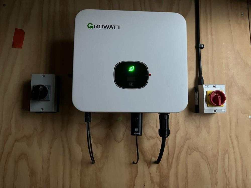
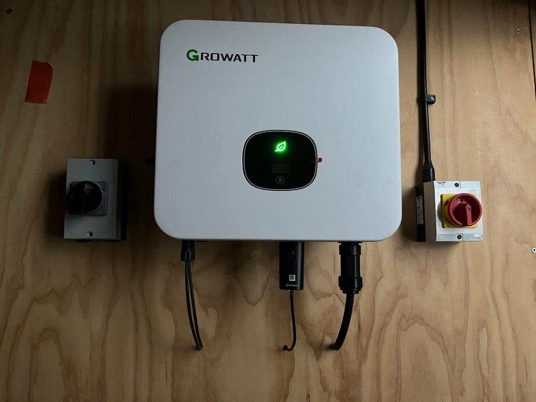
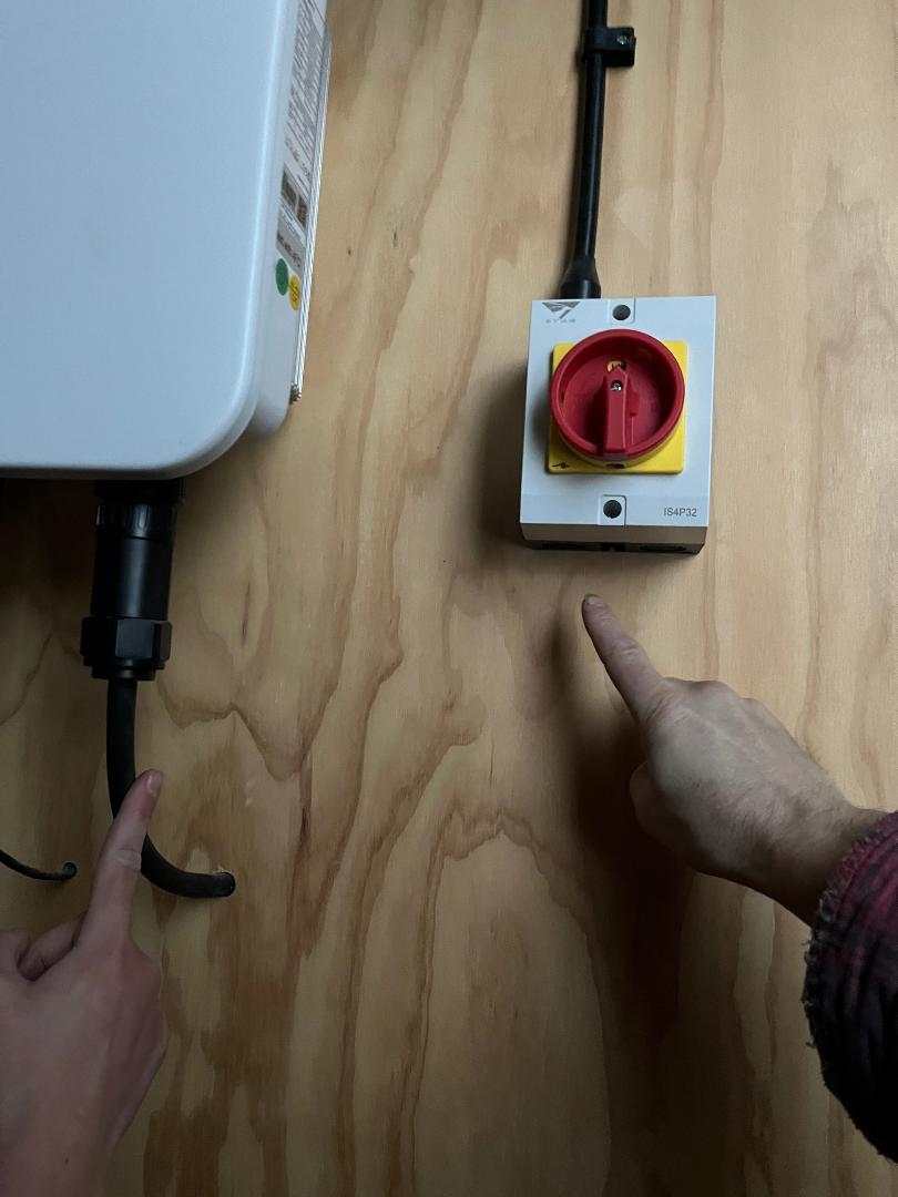
My issue is that I need to change the route of a wire into the red switch in the photos In the second photo I am pointing at the left to a cable out of the inverter that goes through the wall into the service void and then enters the back of the red switch from behind. The issue is that I need to re-route this cable out of the wall so that it enters the red switch from below as I show on the right. It should be a simple 5 minute job for me but I need to know how to isolate the PV so I don’t kill myself. On the photo to the left there is another black isolation switch. Do I just switch that off and also switch the red switch to off and is that all there is to it? Thanks PS I have asked the company who installed for us but they say they would need to send someone out to do this and they are not local

-
Hi @Trw144 can I ask how you laid the engineered flooring after you had the walls completed as I am trying to puzzle out the same thing now. . I understand the mechanics of fixing the wall board down to the correct height so that the floor then slides under and leaves the desired height of shadow gap. My query is how do you set the short board joins? The long lengths are fine as they are fully exposed other than the 10mm or so tucked under the shadow gap. But we will be using mixed lengths of 1.8 - 3m for a floor about 4m x 4m and so the boards need to be joined to get across the full 4m length? I think the standard way to do this is to use a pull bar and hammer but that means somehow getting the end of the bar under the far edge of the board which is under your plasterboard if you see what I mean? While this might be possible at one end what about the other length that you are butting on to? How does that stay in one place as you hammer the other piece? Would it not hammer in tight under your plasterboard on the other wall and mean you have no expansion gap at that side? Maybe use 2 pull bar left and right and two people hammering at the same time?
-
Shadow gap and engineered timber floor??
markharro replied to Sarah83's topic in General Self Build & DIY Discussion
I have the same question as @sarah83 for you @nod. I understand the mechanics of fixing the wall board down to the correct height so that the floor then slides under and leaves the desired height of shadow gap. My query is how do you set the short board joins? The long lengths are fine as they are fully exposed other than the 10mm or so tucked under the shadow gap. But we will be using mixed lengths of 1.8 - 3m for a floor about 4m x 4m and so the boards need to be joined to get across the full 4m length? I think the standard way to do this is to use a pull bar and hammer but that means somehow getting the end of the bar under the far edge of the board which is under your plasterboard if you see what I mean? While this might be possible at one end what about the other length that you are butting on to? How does that stay in one place as you hammer the other piece? Would it not hammer in tight under your plasterboard on the other wall and mean you have no expansion gap at that side? Maybe use 2 pull bar left and right and two people hammering at the same time? -
To refresh this topic when I was looking at the Grohe instal video for the shower set you will see from the attached screenshot that they show two orange fabric seals..... The larger one for the control valve is included in their kit but the smaller one for the hand shower pipe outlet is not. I got in touch with them to mention that it wasn't included in the kit pack and they said that it's not meant to be. They say it's not essential and if you want to use one you need to source it yourself. I would like to fit a seal like this but a quick look online has me struggling to source one. Can anyone provide a link for purchase of one of these fabric type seals with a rubberised circle in the middle to go over the outlet? Thanks.
.thumb.png.2002f628c97aa87172a04c9e36e5420c.png)
-
My other half is seemingly changing her mind about a shower niche after she was adamant she didn't want one!! Annoyingly the studs have backer board on with screw heads and joints sealed etc and in fact one board that part cover a possible niche location is now impossible to remove. I could easily multitool an opening having said all this but what is needed after that? Can I build out the internal frame needed through a window cut in the backer board? thanks
-
I agree but its mainly to satisfy the pernickety "boss". These Steinel ones look good. One question - this is to operate an external LED strip it wired between the mains cable and driver or between driver and LED?
-
LED strip causing MCB tripping! Reason?
markharro replied to markharro's topic in Consumer Units, RCDs, MCBOs
So this has got me thinking. If this new driver lasts a similar time to the one that failed how do you plan to be able to replace these things? I assume you normally fit them in the circuit behind plasterboard. Once hidden away and the wall finished and plastered and painted what do you do if/when the driver fails? should you design in some sort of access hatch? -
LED strip causing MCB tripping! Reason?
markharro replied to markharro's topic in Consumer Units, RCDs, MCBOs
In the end it turned out that the (brand new) driver was the issue. I got send a replacement and now all is well! -
Thanks v much. Be good to get some more input on this as well.
-
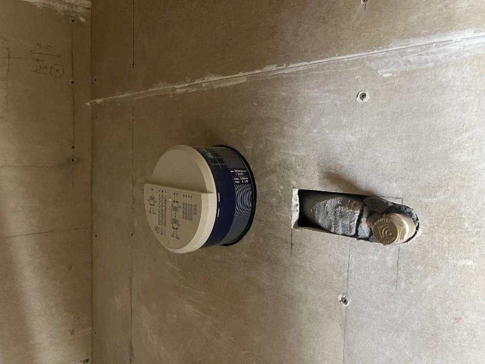
Almost finished the backer board and then will tape before using a tanking roll on product. Can I leave this hole "open" or does it needed sorted and if so how? The reason its there was to fit the cement backer board as the pipe that feeds the outlet to the right pushes out a bit. Thanks
-
LED strip causing MCB tripping! Reason?
markharro replied to markharro's topic in Consumer Units, RCDs, MCBOs
Thanks Dave. First question is how do I tell between mcb and rcd? Once I know that I can check what I have connected to our external power sockets on our shed. Then I might be able to run an extension cord from there. Yes def cut in the correct spot and then sealed with special silicone glue I bought. The thing is after I did all this and mounted the strip in a metal housing and then clipped on the diffuser and then siliconed the end caps I tested it in the house and it worked fine. It was plugged in to the exact same power socket. -
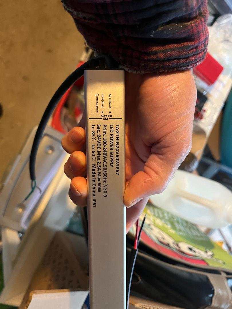
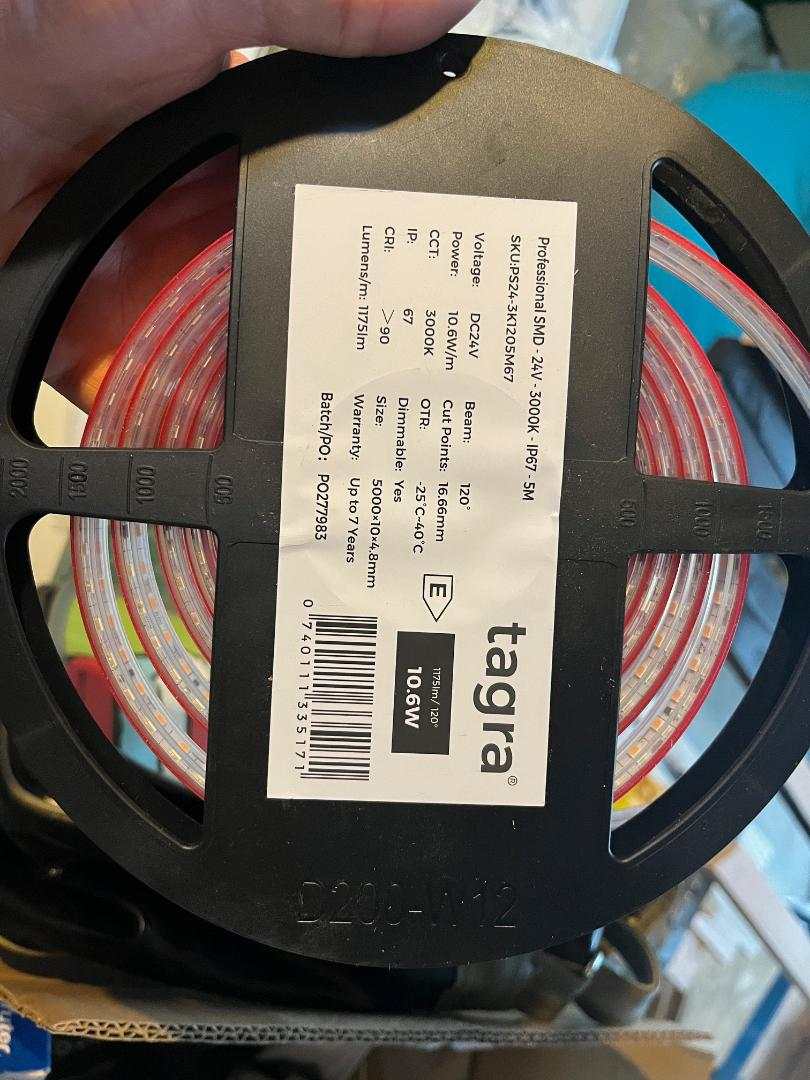
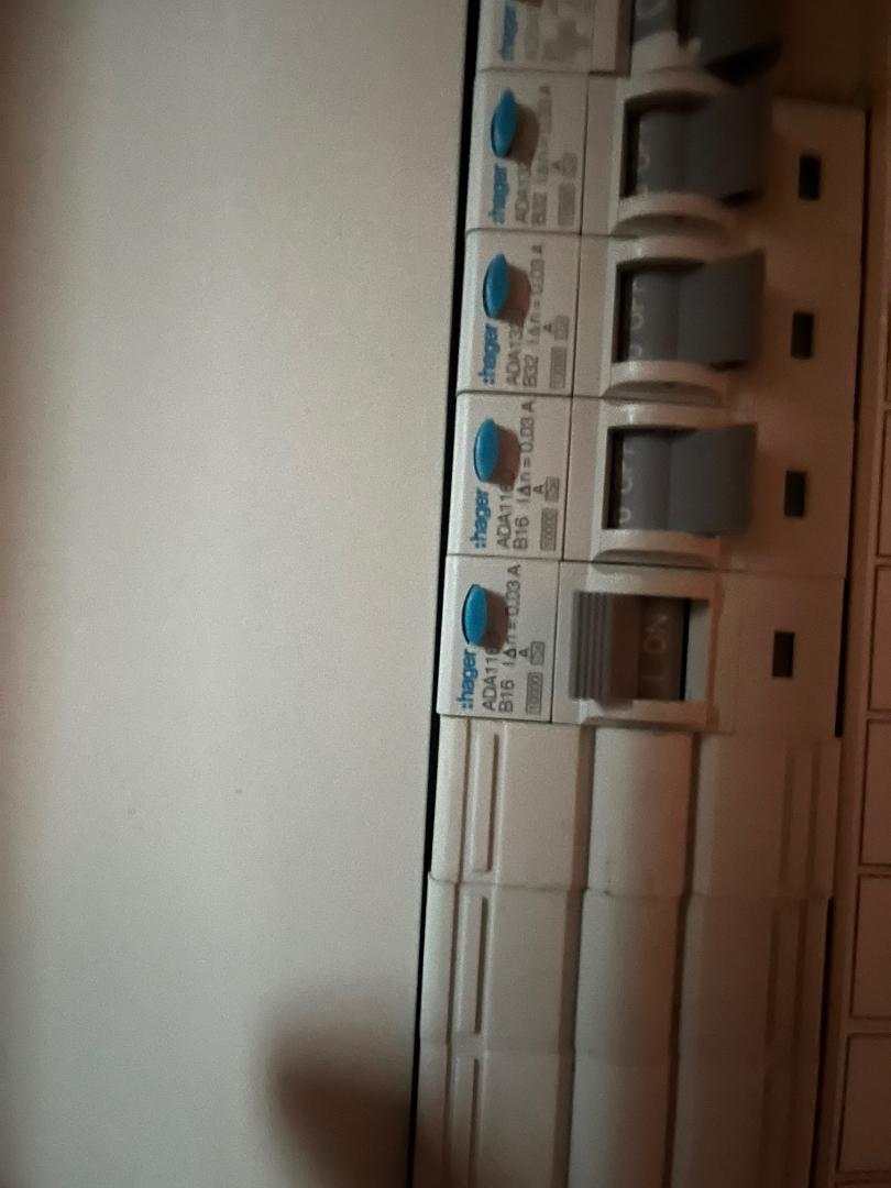
At the moment we only have our ASHP and solar PV connected to our 3phase consumer unit. Other than that we have 4 temporary power sockets energised. We are using these to power our internet router/switch and MVHR from time to time and a couple of lights etc. Also power tools from time to time. I am currently installing a 2.5m external LED strip. I checked carefully with the supplier that the strip and driver are compatible. You will see the specs in the photos. I cut the 5m strip down to the 2.5m required. I added a plug to the mains end of the driver and connected to the strip as a dry run in the house and it lit up as expected. I have now fitted it outside. However on wiring up again to test each time I plug in the MCB trips. The strip doesn't light at all. I am totally puzzled - why would it work first time around with the strip lit and no tripping but now not at all? I have googled and most answers are talking about inrush current but these seems mainly connected to multiple drivers etc. Any other ideas what might be going on? thanks


-
Vaillant ASHP low pressure isues - fix?
markharro replied to markharro's topic in Air Source Heat Pumps (ASHP)
Thanks everyone. Got it reset and will keep my fingers crossed that these are just teething troubles -
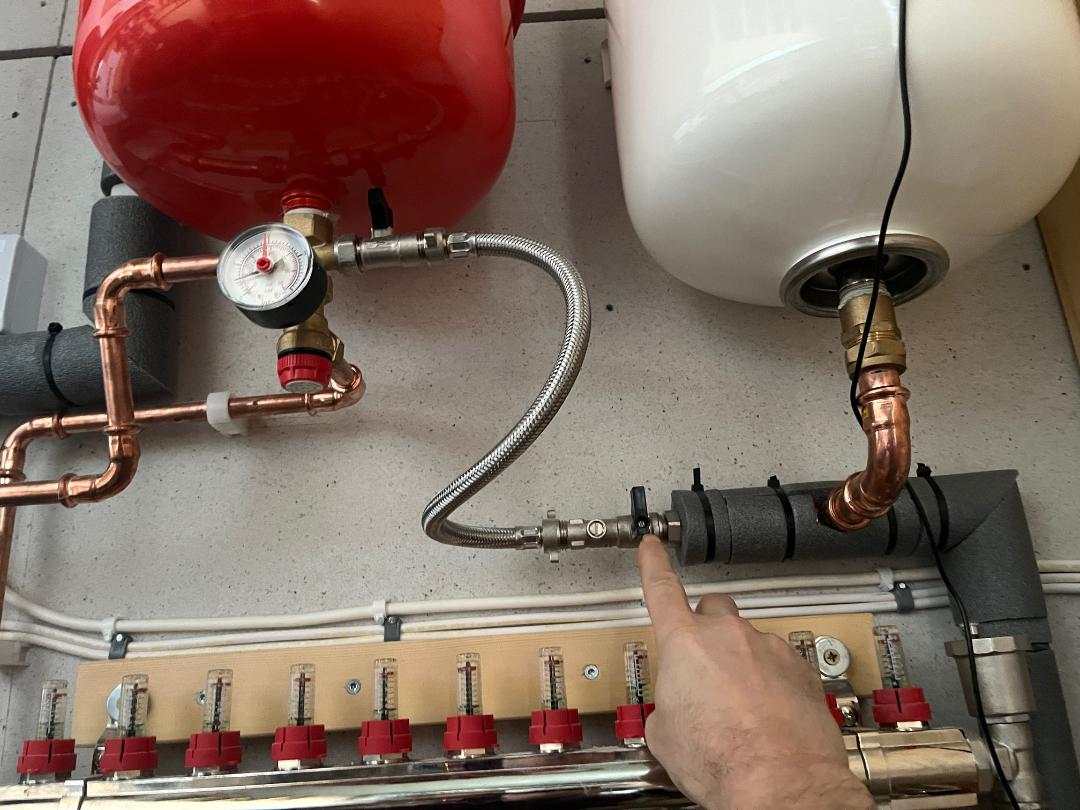
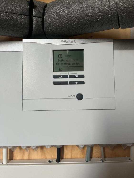
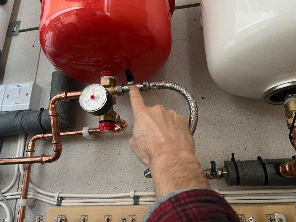
For the second time in about 3 weeks we have this warning showing for low water pressure. The pump was installed in the summer and basically hasnt been used until about 4 weeks ago. We then got this warning. The installer came out and opened and shut the two black valve levers in the photos and it worked again. That was about 3 weeks ago. We have used the heating since then sporadically. Now the warning has come back. Surely this cant be normal!? The installer showed me how to reset the pressure but I cant remember now if I have to open and shut these valves in any particular order? Hopefully someone can advise? thanks

-
I am planning to instal an LED strip to light some recessed timber cladding by our drive. It would be good to be able to trigger the light on with a PIR sensor. Having done a quick google most of these look awful. I need one in black to match our cladding - any recommendations? thaks
-
I cant say I understand this. We have a 3phase supply so can instal PV up to 11.04kW (or something like that) on our existing G98 permission. At the moment we have about 6kW installed. If we installed a standard home battery does that mean it reduces what further PV we could instal because that would be news to me? Why would or is the position different using a car battery as the "home" battery?
.png.1cfde21479e150e791123af2001c0ea5.png)