
JohnMo
-
Posts
12886 -
Joined
-
Last visited
-
Days Won
188
Everything posted by JohnMo
-
There is a roads document that details the slopes required and where the acro drain is located so you don't get slippage on to the road. It basically has to comply with highways regs. Your slope itself is likely to have to SUDs compliant also
-

Changes to planning once house is built!
JohnMo replied to squealeyhealey's topic in Planning Permission
We had a full landscaping plan, but at time of sign off most hadn't been done, BC had zero interest, just interested in the actual house build was over plan. Being anal. Your agreed plans for planning and building control, is a legal document. You are not allowed to vary from the agreed plans, so actually installing frosted glass where it hasn't been stipulated is a breach of planning. Prior to doing so, you need permission. So a throw away statement from planning means nothing really. -
Wheelchair access and patio (part M)
JohnMo replied to iMCaan's topic in Landscaping, Decking & Patios
Really depends how you do it and roof overhangs etc. if required and acro drain will just move the water away out of harms way. Just a matter of planning what you need to do and implementing correctly. -
Really wouldn't bother, tech will change by the time you get it working. Or you will change your phone it it won't work.
-
Wheelchair access and patio (part M)
JohnMo replied to iMCaan's topic in Landscaping, Decking & Patios
Only one access point needed. But we have flat access to every door, either on to decking or patio. But whole house is single storey so why not. Nice future proof, you never know what's ahead of you or your family. -
Assume NI same as rest of UK and the unvented cylinder would require a G3 certificate to cover the unvented cylinder install. The heat pump install would be asking the commissioning person for a commissioning certificate.
-
Wheelchair access and patio (part M)
JohnMo replied to iMCaan's topic in Landscaping, Decking & Patios
We don't have edge as such. Small step down to gravel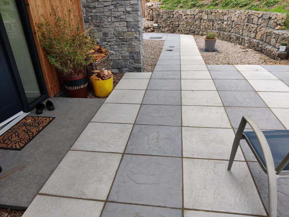
-
What is an inverted heating system?
-
Pretty much exact same. Hep2O will also go into Tectite fitting
-
Wheelchair access and patio (part M)
JohnMo replied to iMCaan's topic in Landscaping, Decking & Patios
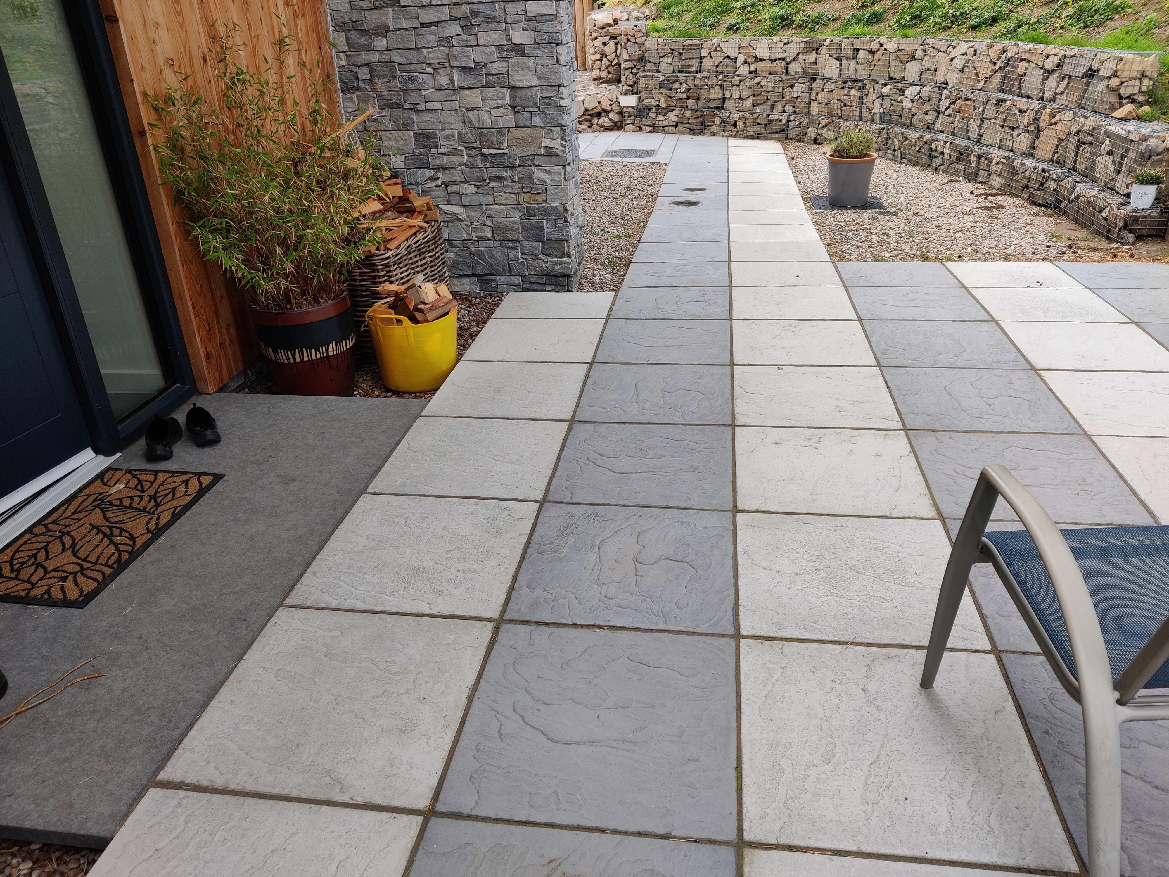
You also will need to a ramp down to your parking area from that. I just made a very shallow incline direct from parking area to the level threshold in paving slabs. Never found weed suspension membrane to work. The weed are generally blown on the wind and find their way in from above. -
Backer board or plasterboard
JohnMo replied to Super_Paulie's topic in Bathrooms, Ensuites & Wetrooms
Never seen a need to tank a shower room and in my 60 plus years and never seen an issue. Only ever used moisture resistant plasterboard around the shower and normal elsewhere. Tiles direct to the plasterboard. If you foam the plasterboard on or batten and screw it's not going anywhere quickly. -
Does the UK really have the most expensive electricity in Europe?
JohnMo replied to SteamyTea's topic in Boffin's Corner
Pretty wide range of pricing there. -
Integrated multi outlet or all mounted. Should be easy to do if you plan ahead Cool Energy do fan coils for bathrooms, with towel rail also
-
Why go mlcp, and not just Hep2O? Hep2O is easy to get, pretty idiot proof (that's why I like it) and no special tools needed. Mixes with copper easily.
-
Well you have answered your own question, as you have already sorted out your storage of the bits. Why build that big, you must rattle about in there
-
And the spares, where did I put them? Bugger I've looked everywhere?
-
No, not high enough to mitigate wind disturbance Would they have applied?
-
Fan Coil Units for use with a (cooling) ASHP
JohnMo replied to ProDave's topic in Air Source Heat Pumps (ASHP)
Good indication you aren't getting much heat transfer. -
running cooling mode? noises
JohnMo replied to Post and beam's topic in Air Source Heat Pumps (ASHP)
What I notice with UFH cooling, it knocks of that uncomfortable couple of degrees at the high end, AND the house actually feels cooler than the gauge would imply. But importantly the recovery time to more normal feeling temperatures is way quicker in the evening. -
Texecom home security products
JohnMo replied to SilverShadow's topic in Networks, AV, Security & Automation
Our last house had a fully insurance approved and maintained alarm. Out of interest, at one renewal time for insurance, I asked to quote with and without alarm and got the same cost. All these things were true if I declared the alarm. Kept the alarm, didn't declare it any more. -
Texecom home security products
JohnMo replied to SilverShadow's topic in Networks, AV, Security & Automation
True -
You have to be careful with hybrid roofs. Otherwise you end up with condensation issues, as you seem to be aware of. Suspect you already have issues, you have a vapour barrier at plasterboard and above it with bitumen vcl. So any humidity that finds it's way in the roof structure is stuck there. My thoughts are adding 25 or 50mm just isn't worth the effort. If you concerned with shrinkage get a thermal camera and see if you have issues. May need a cold night to see if you have a thermal gradient between inside and outside.
-
Texecom home security products
JohnMo replied to SilverShadow's topic in Networks, AV, Security & Automation
I assume this will be a professional installation, otherwise worth nothing as far as insurance is concerned? So would suspect the installer would be the best person to talk with and they would be well aware of the correct mix of components for a good glitch free install of your house. -
Completely agree. Many on are talking about what if.. lots of multiple systems on one circuit etc. Who in the right mind would bother. You are royally ripped off on one system, so why would you buy multiple systems. Plus if your in a flat (the reason these systems exist) where do you put all these panels for multiple systems, most would struggle with a couple of large format panels.
-
Fan Coil Units for use with a (cooling) ASHP
JohnMo replied to ProDave's topic in Air Source Heat Pumps (ASHP)
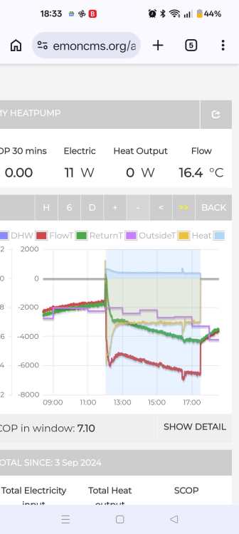
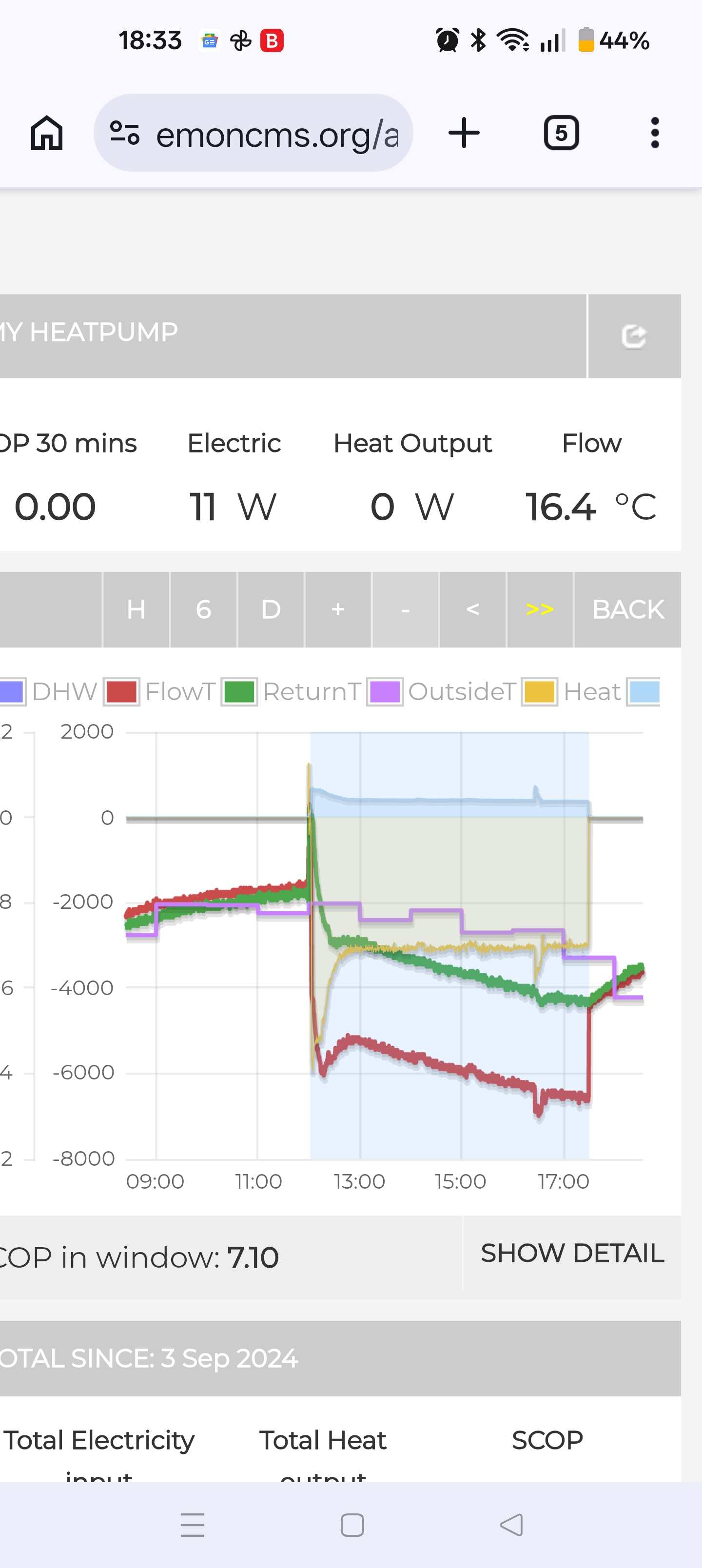
Couple that to heat pump monitor, that will add an electric meter, a few bits and bobs, and you get full monitoring. We have the same heat meter. 4th or 5th push of the button also gives you kW as an instantaneous reading. You have dT available to read. Will give stuff like this, it's ace for understanding what really happening.