MortarThePoint
-
Posts
2294 -
Joined
-
Last visited
Everything posted by MortarThePoint
-
Glulam (inc. service class)
MortarThePoint replied to MortarThePoint's topic in General Construction Issues
Sorry, I should have shared more context and the other thread about the loggia which you have kindly contributed to. My last query there was whether I needed ceiling level ties to constrain the main beams laterally or whether the bracketry would achieve that on its own.
-
I have a deburring tool so can do that bit my self, but they are a nice bunch down at this merchant and I'll put what trade I can their way. Unfortunately, they don't stock Hep2O just PolyPipe and Speedfit.
-
The kindly local independent plumbers merchant sells pipe by the metre and was happy to cut it up for me which was great. Alternatively: https://pipedreamfittings.com/product/copper-tube-22mm/
-
Has anyone found a sensible place to buy pre-cut (e.g. 100mm) lengths of copper pipe to go between fittings? It feels like there should be a market for these as it would save time on site and are particularly useful for people using Hep2O and the other push fit poly systems that then need to reliably connect to compression fittings. I don't want to buy a 2m length of 22mm pipe and a 22mm pipe slice for the sake of 6no. 100mm lengths of pipe. The only place I can find these is on Amazon at high prices and dubious sources. I would happily pay about £2 each which is about double the current rate for 22mm Copper pipe at SF. Same for when I need 15mm ones.
-
I need some beams under a loggia (veranda) with 3.1m spans. The drawing calls for 2no. 8x2 but I'm tempted to go with a Glulam instead for the following reasons: Normal tanalised timber will twist / cup / bow as it dries. The two timbers being joined together would help that but still The total length of the beam is almost 10m including its bearings (atop 150x150 oak posts) so there will need to be joins between sections if done in normal timber. I can have a single length of glulam. Glulam is fun to say The downsides of the Glulam approach are: It's not treated timber It's more expensive: 8x2 joined together. 8x2 is around £3.80/m exVAT around my parts and I'll need to carriage bolts, timber joiners and square washers (£0.25, £0.23, £0.30 ex VAT) about every 400mm so that makes for a cost of £9.55/m exVAT. The Glulam is about £24/m + delivery. As the beam is exterior but under the cover of a roof eave the glulam suppliers are saying Service Class 2 is OK. I could make my own 95mm x 225mm glulam out of tanalised 4x2 at a cost of about £9/m: Timber: £1.60/m * 5 = £8/m Waterproof Urethane Glue: £0.331/m based on 0.16mm thick gives (0.16L/m2) * (4*0.045m) = 0.03L/m , £8.63/0.750 = £11.51/L -> £0.331/m (Soudal Pro 45P D4 professional waterproof polyurethane wood adhesive). Fixings: £0.45/m based on 1no. 5mm x 80mm every 400mm for each joint so works out as one every 100mm, 10/m and they cost £4.50/100 The eased edges would make for bumps in the beam which are a shame. Scant timber is actually more expensive (+33%) than eased edge and I don't know how available it is tanalised. Planing off the eased edge would reduce the timber to about 40mm and the glulam to 95mm x 200mm or raise the number of laminations to 6. It would likely cost a jointer blade too (£12) as well as taking a very long time. It will get painted, so I could not remove the eased edges and fill all the grooves with waterproof wood filler (120ml/m -> £1.50/m). Has anyone else been down this road, either buying a premade glulam or making one themselves?
-
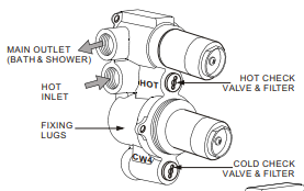
As I understand it you need a single acting check valves wherever hot and cold are mixed and a double acting one where it could be more serious like for an outside tap, washing machine or dishwasher. You also need one before a water softener, though it is debatable whether you need a double or single check valve. I think mixer taps are the most likely to be overlooked. Are most people fitting check valves there? Unvented Cylinder: I have a Caleffi 533201 PRV with integrated check valve to protect the upstream mains supply, but interestingly nothing between the outlet for cold and the outlet to the cylinder. When cylinder fills with cold water and is then heated up, could the water not expand back up the cylinder feed and through the Caleffi manifold into the expansion vessel (or cold) branch? If the next tap to be turned on is a cold one that water would get pushed into the cold branch. Shower Mixers: Not sure why (particularly with an unvented cylinder system like mine), you're supposed to have a check valve on both the hot and cold connections of a shower mixer or mixer tap. I understand the cold side as the hot water is a high category than the cold. One of our shower mixers' instruction manual clearly labels two check valves, whereas the other one talks of a check valve and how to maintain it but doesn't use the plural. The diagram for maintenance shows a position next to the hot feed. There is a similar position next to the cold feed, but that may be empty. Another shower has a cheap eBay mixer bar which may not include check valve(s) so will need to check that. Bath Thermostatic Mixing Valve (TMV): Likely include check valves but confirm. Example Pegler PEG402 "Each tail piece comprises: a housing with union nut and an internally fitted, WRAS approved non-return valve." Basin mixer taps: Don't normally integrate check valve(s), but should people be adding them? NOT ACTUAL ONE - 533112-CST-UV3-PRV-Monobloc-Manifold_DS_06-15.pdf Same as Family Bath Valve - WP1500RC.pdf Master_Shower_Cambridge Manual.pdf

-
I need to have a check valve (double or single?) before all this for a water softener. Won't that form the main constriction? Can you recommend a good check valve that has good flow?
-
Is that because the screwdriver operated ballofix valve is less easy to operate or because it's less reliable? I notice it isn't full bore either
-
Agreed, but arguably they have more justification for insulation (maybe not in the floor) than we do given their AC use. The US obviously doesn't use the same SAP system as us, but they have their own equivalents which look to be voluntary. The HERS index looks most useful an is an inverse scale where 100 represents a standard newly built US home in 2006 and 0 represents a Net Zero Energy home. According to Gemini (summarise by me): The UK Ministry of Defence maintains an overseas accommodation policy framework (JSP 464) that formally maps international energy metrics to the UK SAP/EPC bands for service personnel housing. According to their official conversion methodology: SAP 92–100+ (EPC Band A): Maps to a US HERS score of 0 to 12 (a near Net-Zero home). SAP 81–91 (EPC Band B): Maps to a US HERS score of 13–55 (highly efficient modern US builds). SAP 69–80 (EPC Band C): Maps to a US HERS score of 56–70 (average modern US energy-star builds). SAP 55–68 (EPC Band D): Maps to a US HERS score of 71–100. Therefore, a US home hitting exactly HERS 100 sits right at the bottom edge of a UK EPC band D (or the upper edge of an E). The US New Build Average (HERS 53): Squeezes into the SAP 76 to 81 range, EPC band C or just into B. Fewer than 1% to 2% of all new-build homes in the US achieve a HERS Index score of 12 or less which is SAP 92 or higher. That's a standard newly built US home has a SAP score of about 78 and EPC band C.
-
The difference in average electricity price is a big contributor to the difference for sure. Gemini says that the average in the US is $0.18/kWh which works out as 13p/kWh. Gemini also thinks the average UK electricity price is 26p/kWh. So domestic electricity in the US is half the price it is in the UK. That's a major contributor to the difference in economics. Drawing comparisons between the UK and US housing is complicated by the fact that the average age of US (42) houses is considerably less than that in the UK (63). In particular, a smaller proportion of UK (15%) houses were built since 2000 than in the US (28%). We're interested in new builds though, so the average UK new build house will be much better than the average UK house. Energy generation in the UK is more environmentally friendly too, so it's a triple whammy: U-values, Area and CO2e/kWh. France: ~0.052 kg CO2e / kWh (52 g), heavily driven by nuclear energy. United Kingdom: ~0.129 to 0.207 kg CO2e / kWh (129–207 g), supported by high wind and low-carbon generation. United States: ~0.367 kg CO2e / kWh (367 g), combining natural gas, renewables, and remaining coal. Germany: ~0.380 kg CO2e / kWh (380 g), transitioning through a mix of renewables, gas, and coal. Poland: ~0.810 kg CO2e / kWh (810 g), remaining high due to a heavy reliance on coal.
-
I found the video below and interesting watch from a UK perspective. I'm not knocking it in any way, but it highlights the difference between UK building regulations and the US. It's worth noting that they build much larger homes in the US and are much more likely to have AC. There are also many more homes in the US. In the UK, we go a long way to make our houses perform more effectively in deference to the climate impact, but we all share one atmosphere and a single US home may have an impact 3-4 times as large as a UK one and there are probably 6 times as many. It's easy to start to doubt our approach in the UK, but worth keeping an eye on the personal financial impact as well as the environmental benefit. As an example, at 13:28 they show the floor insulation which is US R10 and looks to be about 50mm of XPS. R10 in UK units is a U-value of 0.57 W/m2K. Air interfaces etc may lower that to something like 0.5 W/m2K, but the limiting value for building regulations in the UK is 0.18 W/m2K and the notional value is 0.13 W/m2K. Just considering that and the larger footprint area in the US makes a huge difference. Various Google searches suggest that the average footprint in the US is over twice that in the UK. If you assume the same weather, that means they pass about 6 times a much heat through the floor as a UK house. The roof and walls also wouldn't come close to meeting UK building regulations values and are of much greater area. Are we over doing it in the UK?
-
Based on the parts I have (2no. 22F x 3/4M full bore valves and 1no. 22F x 22F isolation valve) the best would be a 22M x 22M x 22M tee. In other words, a tee with all connections as plain 22mm pipe. I know I could make such a thing using a conventional tee and soldering, but it would be nice if there was a premade one since each connection made has a chance of failure.
-
Does anyone know where I can get the type of tee shown in the image below? It has two male 22mm connections and one female 22mm compression connection. I would also be happy with a tee that is 22mm male connections all round as I'll be connecting to Hep2O so that would save using a couple on each side.
-
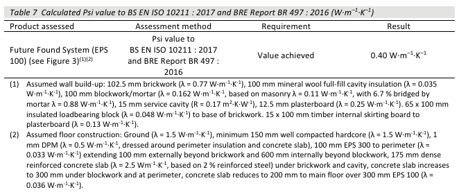
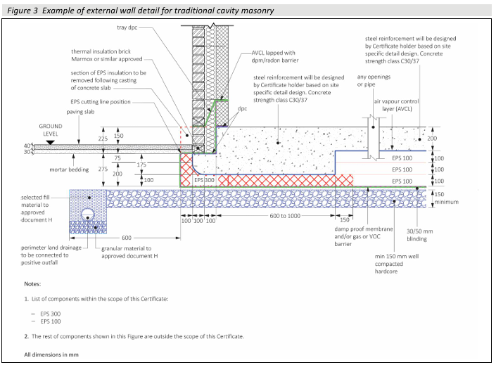
Just found the BBA certificate (BBA 19/5617 PS1 Issue 2) of the BuildLite product and that gives a psi value of 0.4 W/m.K for similar make up but different geometry (100mm wide Marmox) :
-
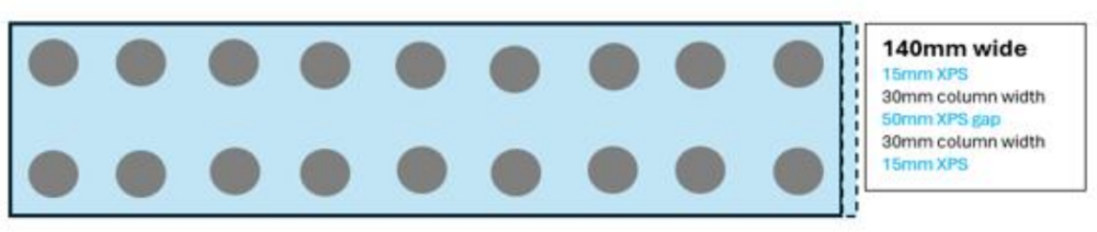
Not being overly familiar with this type of design I find this interesting. That thermal design asks a lot of the Marmox thermal blocks as they are the only line of defence between the cold bricks of the outer leaf and the warm concrete of the raft. The Marmox blocks have vertical columns of epoxy/stone concrete surrounded by XPS, so the vertical direction is the worst from a thermal transfer perspective, but only 6.3% [1] of that sectional area looks to be solid concrete. I am not a thermal expert by any stretch - just trying to ballpark the numbers. Assuming an XPS lambda of 0.033 W/m.K and a concrete lambda of 2.3 W/m.K [0] results in an average vertical lambda of 0.176 W/m.K [2] which is noticeably higher than the value they advertise of 0.05 W/m.K. That may be because the horizontal performance is much better and they quote that value. If using the 65mm Marmox thermal blocks that's going to create a vertical thermal bridge of 0.379 W/m.K . There would also be a lesser thermal path out sideways trough the Marmox block to the soil, but using a total value of 0.4 W/m.K would probably be indicative. This is similar in magnitude to a standard steel lintel, as used above a window. At an average 10C difference for 6 months that would loose 17.3 kWh/m or £1.21/yr per metre based on a heating system COP of 3 (low) and electricity price of 21p/kWh (high). The overall thermal bridge would have to consider the thermal transfer through the slab as well, which I have ignored, but that feels reasonable given the high thermal conductivity of concrete and rebar. [0] IMPORTANT TO NOTE: the Marmox epoxy concrete may be thermally better than standard concrete and mean this value, and subsequent values, should be lower. [1] (pi*(30/2)^2) / ((50+30)*140) = 6.3% [2] (2.3*6.3%) + (0.033*(100% - 6.3%) = 0.176 W/m.K [3] 0.176*(0.140*1) / 0.065 = 0.379 W/m.K [4] 0.4*10*(24*180)/1000 = 17.28 kWh/yr.m I have a make up on my garage raft which is essentially the same without the Marmox thermal block. That's an oversight, but it is a garage rather than a house. However, I think I can improve matters by putting a thin layer of XPS between the blockwork and the soil. The blockwork at the bottom of the outer leaf is a course of engineering bricks and a course of Stranlite 140mm 10N blocks. With the change as pictured below, ignoring horizontal heat flow through the insulation (yellow) and assuming perfect thermal conductivity in both the slab concrete (light grey) and engineering brick (brown), I can consider just the vertical heat flow through the Stranlite block (dark grey). It has a lambda of 0.43 W/m.K , so that works out as a thermal bridge of 0.43*0.140/0.215 = 0.28 W/m.K which is actually comparable to the Marmox thermal block. Interesting. Looks like I have an improvement worth making there. Tweak to include horizontal heat loss through the added XPS: 50mm of XPS would have a sideways thermal bridge of 0.033*0.215/0.050 = 0.14 W/m.K which can probably be halved assuming a linear temperature gradient across the height of the Stranlite block. 0.28 + (0.14 / 2) = 0.35 W/m.K , so still similar to the Marmox thermal block. Now: Improved:


-
Glass balustrade fixing to Glulam beam
MortarThePoint replied to BotusBuild's topic in Windows & Glazing
I see, I thought the aluminium was a trim over the glass which was bolted directly to the timber. -
Part B fire safety second floor protected route design
MortarThePoint replied to PSC88's topic in Building Regulations
I guess they don't worry about the WC which is good. -
Glass balustrade fixing to Glulam beam
MortarThePoint replied to BotusBuild's topic in Windows & Glazing
Looks great. Is there no concern that conventional timber will move as it dries and transfer stress to the glass panels? O don't suppose that's an issue with Glulams though. -
I'm surprised it wasn't developed by NASA
-
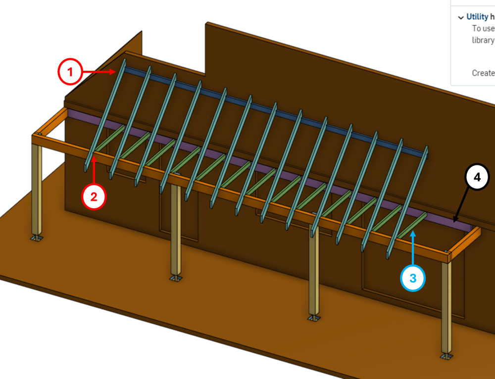
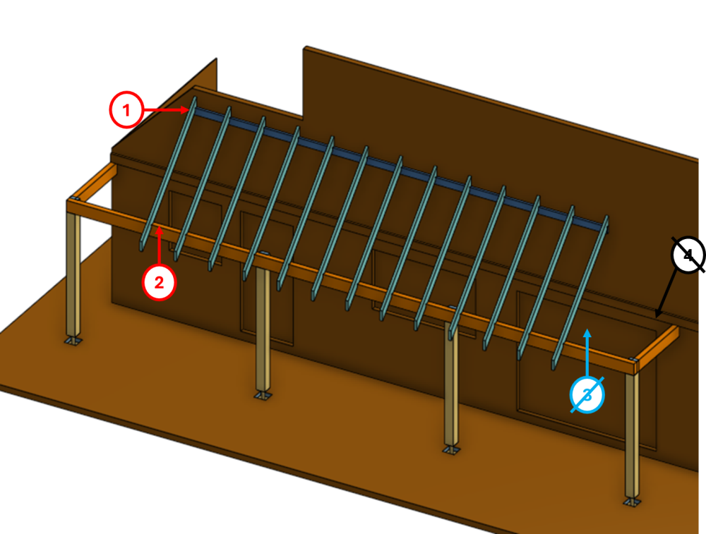
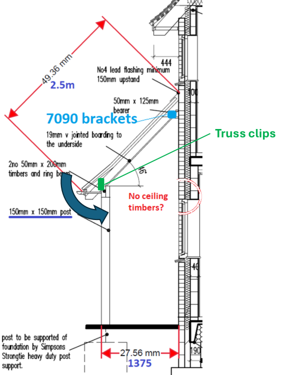
Finally gearing up to build some of this after a long delay. I'm happy using 7090's both sides at the top of each rafter to connect them to the ledger board (labelled 1 in the images below). It occurs to me that truss clips could be an option here too, but I would want something to constrain the rafters horizontally at their top connection to the ledger. If using 7090's there, I would need to raise the ledger so there is a better interface rather than resting the rafter on the ledger using a birds mouth. That would be easy enough. Truss clips on the outside of the lintel beam (labelled 2) feels natural and they would get hidden but the soffit there. I'm still a bit unclear as to whether you think there needs to be horizontal bracing of the posts and lintel by timber "ceiling ties". I have shown two options below, one with and one without. The timber ceiling ties are coloured green and labelled 3, whilst the ledger that terminates them against brickwork is coloured purple and labelled 4. I can appreciate that the lintel would need to be displaced downwards to allow the movement shown in the third image below, so is that why ceiling level ties could be omitted? With timber "ceiling ties": Without timber "ceiling ties": Resisting moment:
-
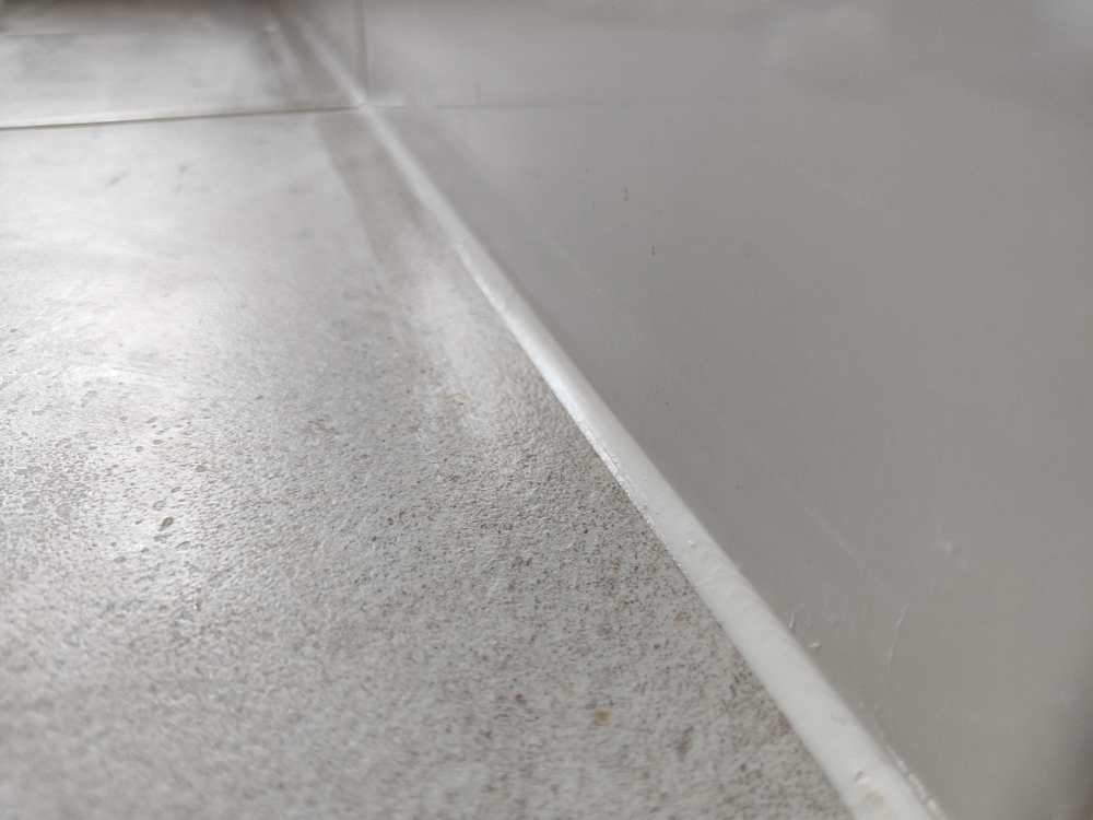
Charlie DIYte has a good video all about applying Silicone [link] and makes some good points. A Cramer Fugi kit is being used. The issue we are getting is a shiny film being left on the tiles after tooling. Hopefully the photo below shows this OK. That raises to questions: How do we stop that from happening How do we remove it when it does happen I'm having some high stakes conversations with the person on this job (SWMBO), so a tactful solution would go a long way.
-
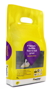
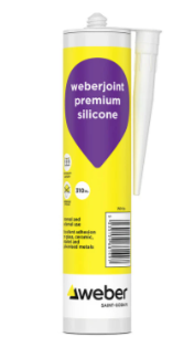
I think the main quandary is what colour silicone to use on the white shower tray, chrome shower enclosure and white toilet when I have grey tile grout on the floor and walls. White feels the natural choice, even if it does create corners that have grey silicone coming down the wall and then white silicone going along the tile to shower tray joint. White feels natural against the white shower tray, but white between the chrome enclosure rail and grey tile is less obvious. The grey tiles have Weberjoint Ice Grey grout and I've got the matching silicone:

-
I meant to say the grout is the same as the tile colours so have now edited it to make that clear. In the first room I mentioned, it's white grout on walls and grey grout on floor. The other room has grey grout all round
-
One of the two tilers I used doesn't grout corners and leaves it to be siliconed with colour matched silicone. The other tiler didn't, but I am inclined to silicone the corners there too. When the walls are white tile & grout and the floor is grey tile & grout, what is the convention in terms of silicone colour for the joints between floor and walls? I assume I use the same colour silicone as I am using in the wall-wall joints, so white. In another bathroom, I have grey tile & grout on both walls and floor. That leaves me wondering about the joint between the shower tray and the walls (and floor too). Also up the shower cubicle edge strips (chrome).
-
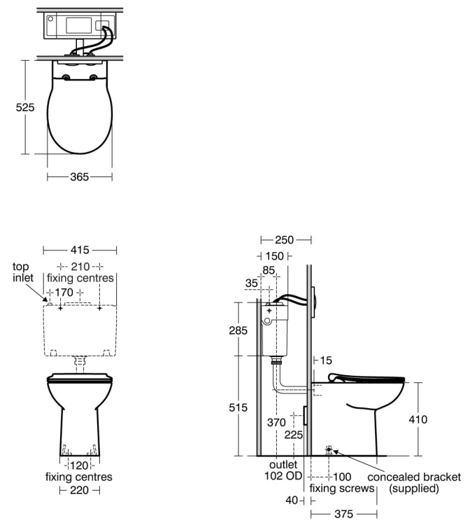
This toilet is worth remembering as it has an exceptionally high outlet at 225mm: Armitage Shanks Contour 21+ Back-to-Wall Rimless Toilet https://www.idealspec.co.uk/catalogue/bluebook/toilets/back-to-wall-toilets/contour-21-back-to-wall-rimless-toilet_p4015.html https://www.aqva.co.uk/Bathrooms/233963