MortarThePoint
-
Posts
2198 -
Joined
-
Last visited
Everything posted by MortarThePoint
-
Hep2O Clipping Distances
-
@WWilts How did you sort this in the end? I have a similar challenge needing a balustrade along the top of a steel beam
-
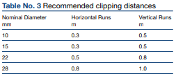
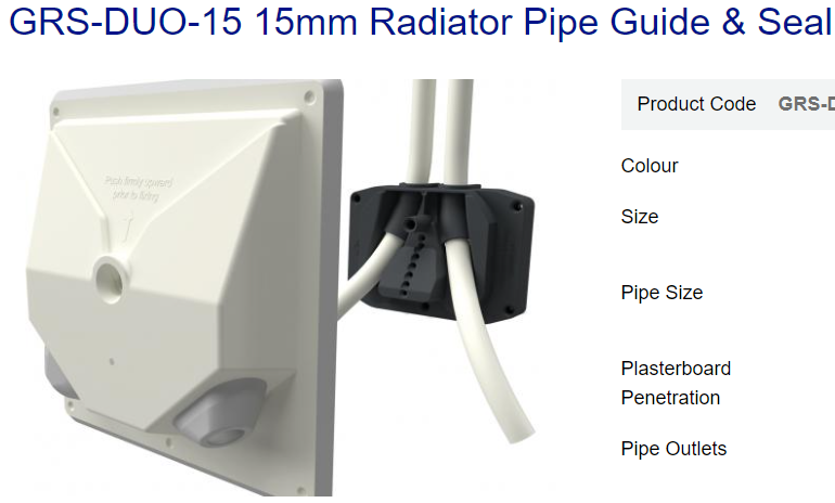
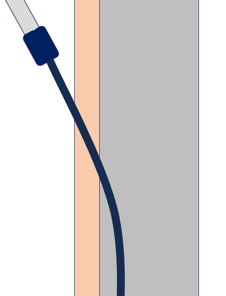
It's a more general question of when you have a Hep2O pipe that leads to a basin and is coming up from floor level. Do you: make the Hep2O visible out of the floor and do the vertical all on the wall surface keep the Hep2O in the wall and then exit at a shallow angle part way up and then connect to a flexi adapter swap to copper in the wall and exit the wall in copper Here is a rough diagram of option 2 with the blockwork in grey and plaster in pink. The Hep2O is dark blue and then it's connected to the flexi. Just plastering round the pipe would make it hard to have a nice finish and also risk damaging the pipe. It's a common thing to do with radiator pipe and I have seen a number of products for 10mm pipe but also found this: https://www.manthorpebp.co.uk/air-leakage/radiator-pipe-guides-and-seals-–-increased-thermal-efficiency/grs-duo-15-15mm-radiator
-
@Nickfromwales You like to keep things tidy. What do you do when you have Hep2O in the plaster leading to a basin?
-
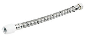
What would you recommend for the last bit of a water connection when using Hep2O? If I have a pipe going up a wall and ideally chased in, should I use an elbow to come out of the wall or keep going with the same bit of pipe and then use something like one of their flexible connectors? That would leave a potentially ugly to plaster around bit though. https://www.screwfix.com/p/hep2o-push-fit-flexible-tap-connectors-15mm-x-1-2-x-300mm-2-pack/1250f For showers I am swapping to copper which then sticks out of the wall. I have a stand alone bath as well which has taps on the less visible side. It still feels a bit funny to have Hep2O jutting out of the floor all the way to the taps, but I guess why not.
-
RCBO for Mitsubishi Ecodan (11.2kW)
MortarThePoint replied to MortarThePoint's topic in Consumer Units, RCDs, MCBOs
Given how hard it is to find Type F RCDs or RCBOs from sensible places I'm doubtful the majority of people are using them. CEF list a 40A type F RCD for £160+. That's about all I've found -
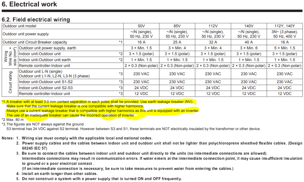
The schematic of my ASHP system design calls for a "30mA Type F RCD". I think that's out of date now and would need to be an RCBO. What type of RCBO do I want to use for this? Type / Curve and how do I reflect the "Type F RCD" requirement? From Ecodan Installation Manual:
-
What do you do at reveals when doing sand and cement (S&C) plastering on walls? Do you line with plasterboard as normal and then skim over both the S&C and the plasterboard with MultiFinish?
-
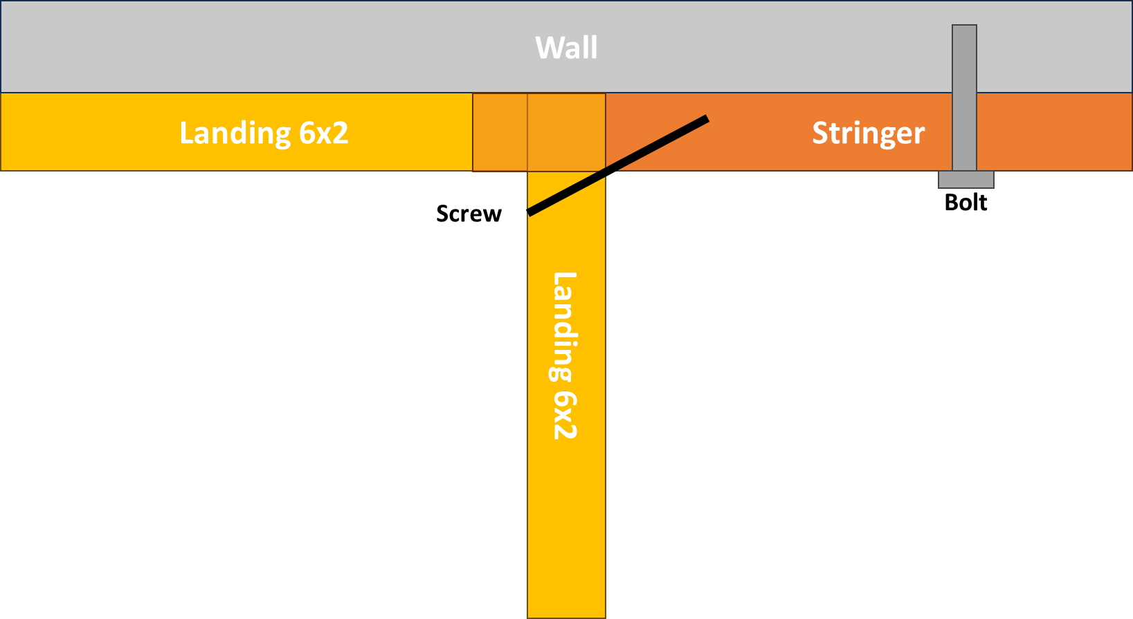
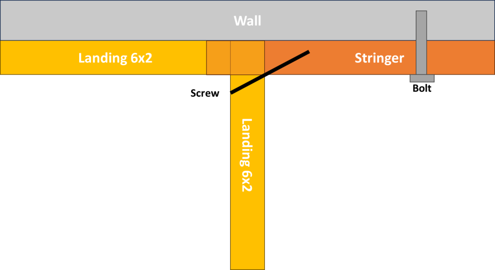
The 6x2 of the landing against the wall was presumably in line with the stringer, so did you toenail it through the landing's front 6x2?
-
The picture hasn't uploaded for some reason
-
What type of metal bracket? A CAD drawing would really help if you are able to.
-
How did the it attach to the half landing?
-
I'm interested in how the right hand stringer is mated to the skirting board at the top. Do you have a close up of that?
-
I want to do the whole thing myself and have the satisfaction, but the newel to stringer m&t joint is intimidating.
-
It's the beginning of the end for a business when it expects it's customers to bear the price of its poor management. A well trodden path sadly.
-
Stairbox are much more like it. £2800. Do they have are mortice & tenon newel to stringer connection?
-
If I cost up my staircase in parts, it works out as about £1600. I have just had a quote from the same company that supplies the parts and its £4500. I know there is work in the cutting and assembly, but it doesn't feel like £3000 worth. Without the CNC machines, it feels like it would take an experienced joiner 1-2 days to cut everything and then perhaps similar to assemble to the same state that you receive a staircase in. That means you're looking at perhaps £2400 compared to the £4500. Mass production should make the staircase manufacturer cheaper. What am I missing?
-
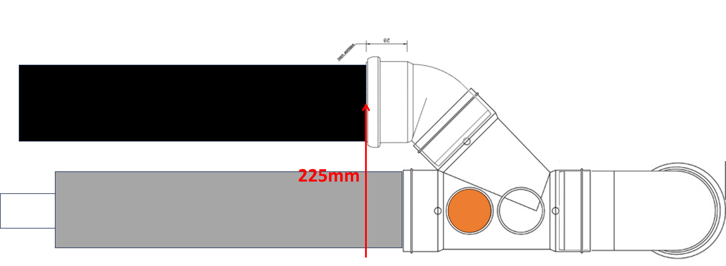
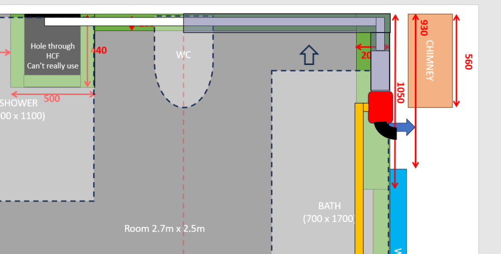
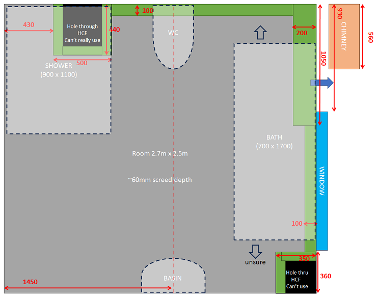
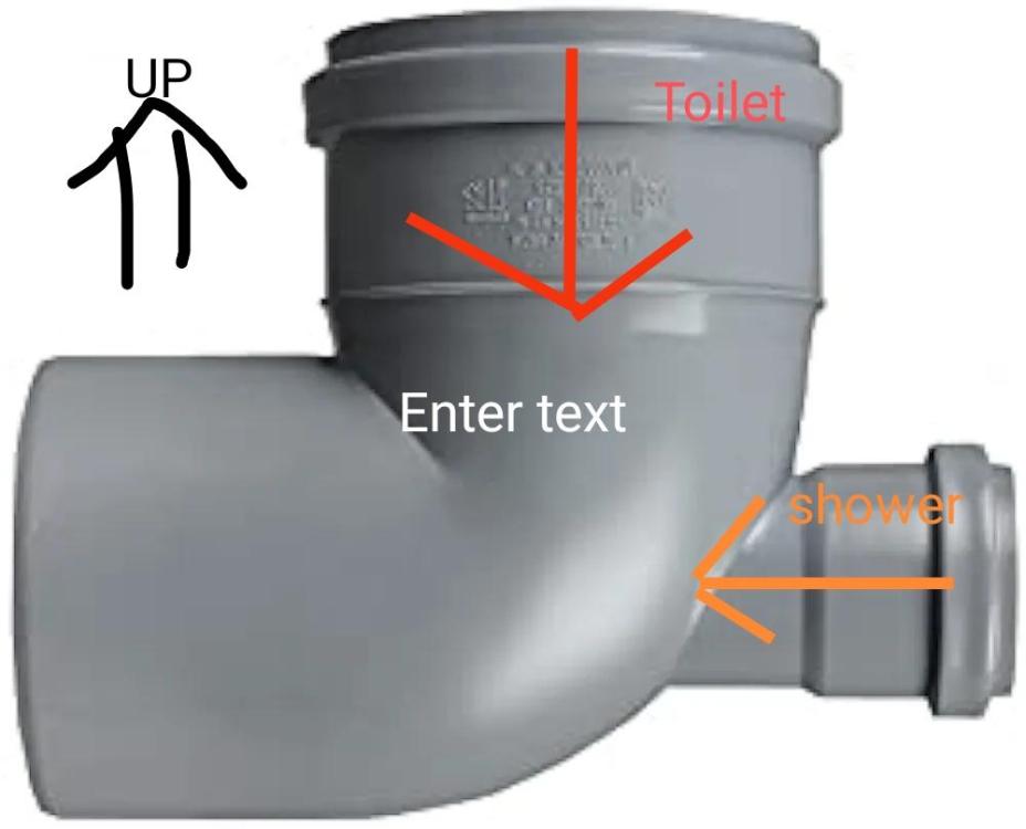
I might be able to do something a little similar passing the 50mm shower waste underneath the toilet 110mm and the having it change to 110mm for about 500mm before the using a Y on its back. A challenge is that the Toilet pipe ends up centred about 225mm above HCF at the junction so with the about 2.0m of run that makes it 225mm + 2.0m * 18mm/m = 261mm. A bit more to allow fall between Y and the 90 bend exiting the room makes for 270mm. If screed is 60mm and if tile adds 10mm that would put the pan connection at 270 - (60 + 10) = 200mm above tile which is about 20mm too high for most toilets. Closer than I feared it might be though. The bath pipe could offset vertically near to the boss so as to slop flow towards the bath. Can I be sure the boss wouldn't get blocked with poo?

-
In terms of the whole room, here's what I am up against: Room 2.7m x 2.5m ~60mm screed depth
-
Cross post sorry, a good length of 110mm before the tee seems sensible. Not sure I can manage that though.
-
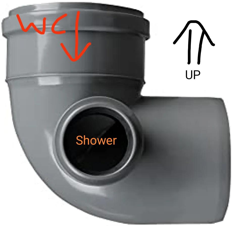
Are you thinking like one of these laid on it's back as shown here

-
No it is sold, eg on Amazon, and I can see how OK if waste pointed up
-
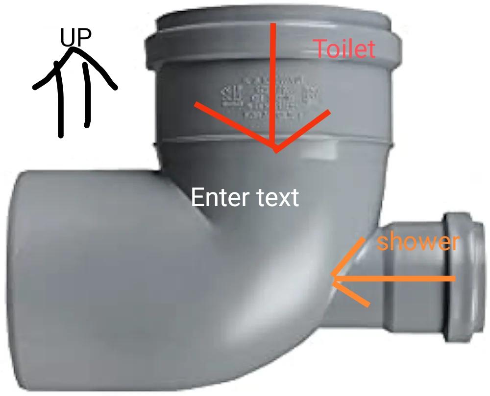
Pretty clear cut then I had concerns too, is this better

-
I need to get a toilet pipe and shower waste (plus others but similar principle) out of a room without passing much below FFL. My only thought is to do something like the attached image. It doesn't feel ideal, but is it a no-no? The exit of the bend would then pass through the wall and to a bend 90 heading down. I want to avoid joining the waste pipe the other side of the wall as that is outside and will increase the visual impact.
-
Staddle Stones vs Post Bases
MortarThePoint replied to MortarThePoint's topic in General Construction Issues
Why would it have to be big and flat. If anchored the staddle stone to the concrete pad and the post is anchored to the staddle stone I'd hope it can be something like 200mm x 200mm x 200mm. It would be better if I could find a rebar post anchor with a longer piece of rebar as then it could pass all the way through the staddle stone and be structurally connected to the concrete pad. I'd prefer something that doesn't end up visible, but I could bolt one of these to the top of the Saddle stone: https://tradefixdirect.com/post-supports/simpson-concealed-post-base-1-1