MortarThePoint
-
Posts
2198 -
Joined
-
Last visited
Everything posted by MortarThePoint
-
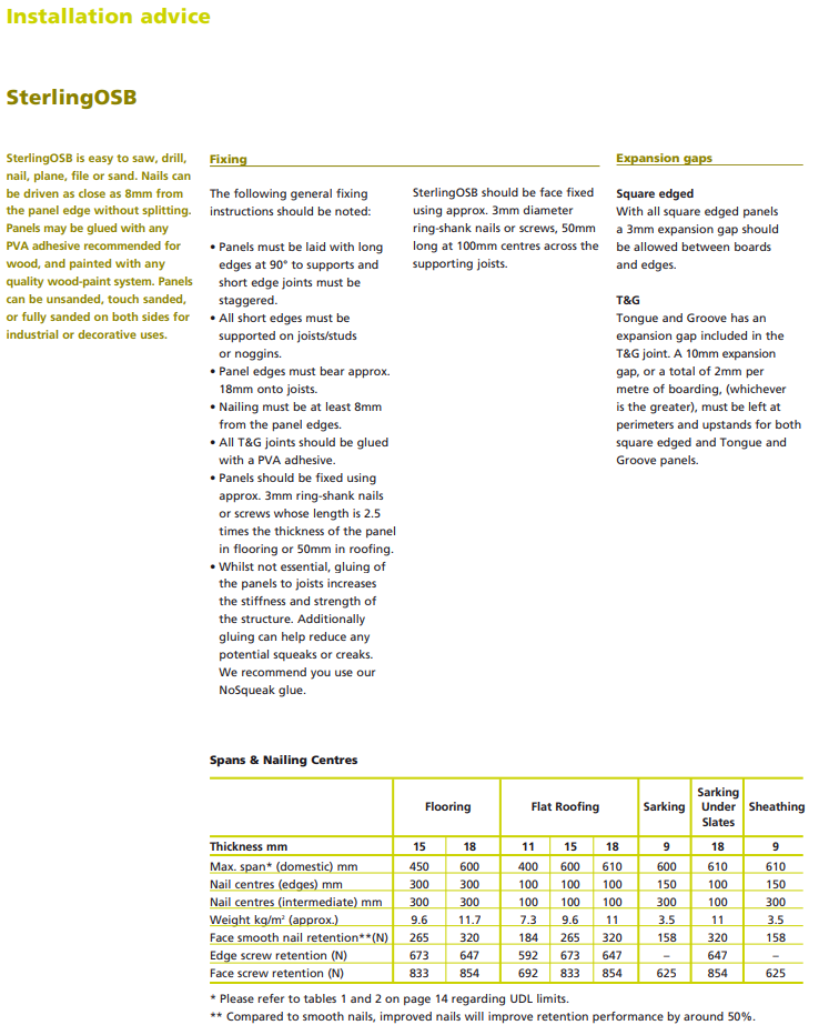
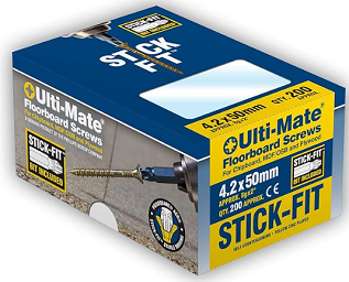
This is an old thread, but a useful one and it doesn't feel right to start a new thread asking a similar question given the good advice here from the likes of @Nickfromwales, @joe90, @PeterW and others. I'm trying to avoid PU (polyurethane) adhesives which is a long story, but all of the expanding adhesives look to be that. I don't want squeaks and I can see that the PU glues would work a treat at that. It's expensive, but I am wondering about using CT1 instead as it is important to have something that stays flexible. How does that sound? Can anyone think of a better choice? Like @Dudda I am using T&G OSB, not chipboard [SterlingOSB so zero added formaldehyde]. Their OSB installation advice is to use PVA glue in the T&G joints. It also says "We recommend you use our NoSqueak glue" which I see is a PU glue (link). Other glues they have include Caberfix D4 (PU) and Caberfix Joist&Joint (PU). For the T&G joint I can happily use a PVA like Everbuild D4 or 502 Wood Adhesive. I've used quite a bit of those and they're good although the bottles are awful. I can appreciate the benefits of an explaining glue, but it's the PU aspect. I'll use loads of screws (100mm c/c) along the joists. I like the look of the Ulti-Mate or Floor-Tite ones. If I lay the label's famous 6mm bead of CT1 it goes 9.25m. That would need about 20 tubes of CT1. It may turn out it squeezes out too much at that width in which case it may go further. https://www.falconpp.co.uk/media/1060/osb-sterling-brochure.pdf

-
2 days for the walls of one room, or 2 days do do the walls of all three rooms? If the latter, that's about 2+1+1=4days total to do all three bathrooms.
-
Thanks @nod ! So it's sounding like the 3 bathrooms should take the tiler 12 days total (3 days per room for walls and then 3 days for all floors)? Or was it 9 days total including prep and grouting? I've been quoted £52/m2 for bathrooms to include adhesive and grout and then £12/m on top of that for laying decoupling mat (inc adhesive but ex mat itself). That's a lot more than I had expected and so I was wondering if I was underestimating the time it would take. The rooms aren't complex (i.e. no alcoves). Looks fantastic. 25 - 30m2 per day at £22/m2 is really good money ~£600/day, but I guess that doesn't include the prep work. I see yellow decoupling mat. Is that Durabase or Nassboard?
-
@nod and others, I was hoping to sanity check how many days of effort I should expect a single tiler to take tiling three bathrooms and a toilet. Shower areas are pre tanked with Aquaseal and shower trays are fitted. Walls are tiled up to about 1200mm and that's just into the bottom of one window per room with a tiled cill. Bog standard 6" x 6" tiles. There's a bit of boxing out which is ready to be tiled. The floors have underfloor heating, so decoupling mats to be fitted too by the tiler. all measurements m2 or m. A rough idea of how long this will take would be really helpful

-
Steel studwork guidance - cannot find the thread
MortarThePoint replied to phatboy's topic in General Construction Issues
GL1 is for making Gypframe ceiling or lining a wall: For a stud wall you'll likely want their standard c-studs (link) and floor channels (e.g. 50 FEC 50). They are available in various widths from 48mm, 60mm, 70mm, 92mm, and 146mm. Depending on board thickness that is then lined with, the overall thickness ranges from about 73mm upwards. Going with board thinner than 12.5mm is probably not wise. I have stuck to 15mm plasterboard (mostly Duraline). At abutments, I have used standard c-studs bolted to the blockwork using Pan Head Concrete Screws at 450mm centres (i.e. every other block). I think that's consistent with the BG recommendation, but do check. Screws and plugs would be good too. GL11 looks the same sort of thing but is a hammer fixing which I have typically avoided, but that's just me. -
A tiler has recommended this stuff: https://www.amazon.co.uk/dp/B088MM6B94?th=1 Works out about £5/m2 ex VAT Anyone seen it before?
-
Staddle Stones vs Post Bases
MortarThePoint replied to MortarThePoint's topic in General Construction Issues
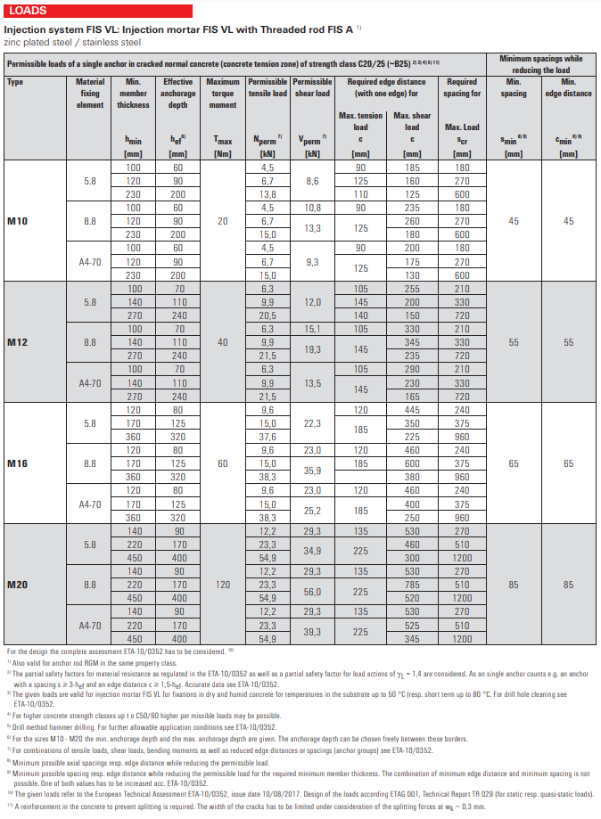
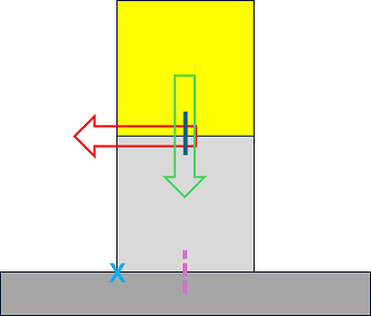
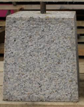
Thinking about the resistance to lateral forces (e.g. heaped logs), horizontal movement of the post would require one of the following: the staddle stone rocking over: I think this would come down to a battle of moments between the horizontal force applied at the top of the staddle stone and the vertical force applied though its centre (assume sold footing). The moments being about the X. Based on a 230mm high staddle stone which is 150mm wide, the horizontal force would only need to be (150 / 2) / 230 = 33% of the vertical force to start the staddle stone rotating if there was no tension resistance at the base of the staddle stone. Each post should carry about 3.6kN vertical loading of tiles alone, perhaps less for the corner posts (though hip tiles are heavy) so say 2.4kN. That means a horizontal force of 33%*2.4kN = 0.8kN or 80kg would start rotation. I'd hope that's a pretty high loading for things that might rest against the post? Some added 'safety factor' would come from using resin mortar to 'stick' the staddle stone down as well as securing a pin (e.g. 16mm x 120mm) between the concrete footing and the staddle stone. Also, some staddle stones are tapered adding to their width at base (180mm vs 150mm) and so improving the moments calculation. the staddle stone sliding: If there is no pin or mortar/resin at the bottom of the staddle stone, the only resistance would come from friction. [link] says "PCI's Design Handbook says the concrete-to-concrete friction factor for dry conditions is 0.80. The latest edition of PCA's Concrete Masonry Handbook, Appendix A, gives a precast concrete-to-concrete masonry friction coefficient of 0.4 based on a safety factor of two." Again, using the vertical loading on the staddle stone as 2.4kN, that would need a horizontal force of 0.4*2.4kN = 0.96kN = 96kg for the staddle stone to start sliding. That has a safety factor built into the calculation, but resin and a pin coupling the staddle stone to the concrete footing would help. the post getting pushed off the top of the staddle stone: There is a pin 16mm x 30mm to resist this. Assuming the pin is vertical, the post wouldn't get an upwards force to push it off the pin. Consequently, this could only happen if the pin was pushed through the wood of the post. I've no idea how much force that would take, but it feels like it would be a lot of force even for a softer wood like C24 let alone something like oak. uplift lifting the post off the staddle stone: given the size of the roof and weight of the tiles this didn't seem to be a concern. Also, ceiling ties will help resist this movement. something would have to break It looks (table below) like this resin mortar used with just an M10 threaded rod embedded 60mm would provide a maximum tensile load of 4.5kN and maximum shear load of 8.6kN both of which are much greater than the resistance associated with the post's vertical loading and so greatly increasing the amount of load that would need to be applied to the post. @Gus Potter am I thinking about this in the right way? The picture of the failed staddle stone above scares me a bit more than this now I think. https://www.fischer.co.uk/en-gb/products/chemical-fixings/injection-mortar/injection-mortar-fis-vl/539461-fis-vl-300-t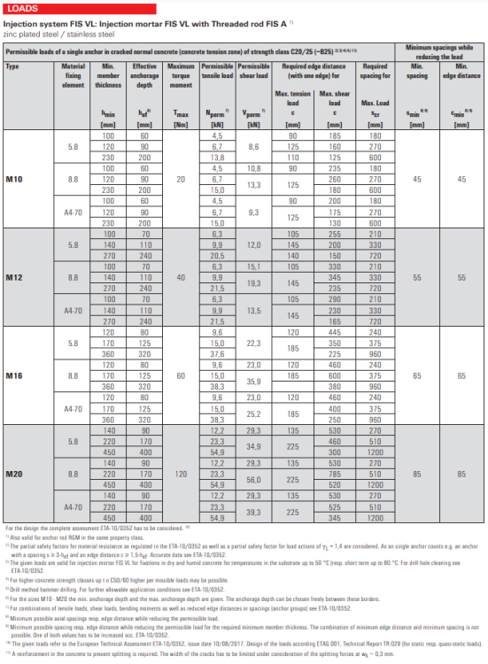
-
Socket Heights (English Regs)
MortarThePoint replied to MortarThePoint's topic in Regulations, Training & Qualifications
I agree, 450mm looks too high but dems da rules. Unless you are renovation or extending as I understand it. What is the green line you mention? Is it the level of the screws? -
Yes please
-
I'm selecting paint for our new build and wanted to tap into all the experience we have at Buildhub in what paints have worked well and given an attractive and durable finish. Paints can be more expensive per litre, but obviously if they go on thinner or most importantly save the labour cost of an extra coat, there are much bigger savings to be had. The poll tries to include the usual suspects, so hopefully I haven't missed any key ones. It is mainly focused on walls rather than ceilings, though that may not make a difference.
-
Is that 30m set by regulations or looking at local emptying companies? If the later, you may just be able to buy a length of compatible hose and store it for whenever they come.
-
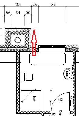
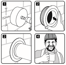
Below is a rough diagram of our main bathroom. The shower, toilet, bath and basin will all converge and exit through the wall to a soil pipe on the outside. Viewed from the front of the house, it is hidden by the chimney. I am wondering how close to the chimney to have the pipe. Is there any conventional wisdom on what's going to look right? It will exit the wall into an elbow and then go vertically down (no pipe above wall entry point). I'm also conscious that there are extra wall ties at the corner, so there is a reasonable chance I'll be hitting one of those. I had hoped to pilot drill (10mm) from the inside and then core drill (117mm) from the outside. I wanted to do it it that order so I get the height correct relative to the floor, but I may not be able to get the drill in to do that since it is below screed level. It may just work since the screed is around 50mm thick. I plan to tidy up on the outside with a pipe snug.
-
Is there much more to the article that how cheap panels have become?
-
That's amazing That's the normal way of looking at it but if you a considering it's cost Vs other roofing/cladding/etc it's very relevant. It's about the same cost as European Oak timber cladding so you could even put it on the walls of an outbuilding as well as the roof.
-
Interesting concept, amazing state of affairs when solar panels are cheap enough for that I can quickly see panels for £50/m2 (500W panels, 2.1m x 1.1m) which is only about double the cost of plain clay tiles.
-
I assume shower trays are a different matter though as they get tiled down to on the wall don't they?
-
Am I right to think toilet bowl and basin pedestal don't get fitted until after tiling?
-
The plasterer is pretty much done now, so the next external trade I have is the tiler who I am currently looking for but thinking about what I need done before they start. The rooms to be done are: Bathrooms (floors, walls to just over window cill level and shower cubicles to above head height) Loo (floor possibly wall to just over window cill level) Kitchen / Family room (floor) Utility (floor) I am trying to work out the jobs I need to get done before the tiler can start and think the list looks like: Bathrooms: plumb 110mm soil pipe to toilet position but not fit toilet(?) plumb shower feeds to shower bar tank shower area fit shower tray and waste plumb shower waste to soil stack fit & plumb bath with box-in frame but not fit panel (v-groove timber) plumb (feed and waste) basin as far as is behind tiles but not fit basin unless it is solely wall mounted (i.e. not vanity or pedestal) Loo: fit any plumbing connection points that are to stick through the tiling understand how waste will connect to stack connection in floor and make any adaptations needed Kitchen / Family: trim island 'conduit' (110mm soil pipe used) to near flush with floor so it doesn't stick up too much above tile though careful to avoid allowing mopping water to enter this so worth being >1cm above finished tile level extend screed into the exterior door thresholds. this is because I had the screed done before fitting door steps or doors (wouldn't do that again) Utility: fit door lining to cupboard extend screed into the exterior door threshold Screed was fitted >12mo ago and I have already had the UFH flow higher than likely end use temperatures. Any thoughts as to what I have overlooked?
-
You have to bear in mind each sales person is going to try to make theirs look better. Even if there wasn't glue, the beads would fill the space. I like the draining capability of beads. Watch some YouTube videos of that. Mineral wool on the other hand soaks it up and can go mouldy, though the newer wool may have biocides to stop that. A patchy installation should be observable with a thermal camera in cold weather. As a retrofit I would concentrate on minimising the negatives rather than maximising the positives.
-
Was that a complete reskim then? If so did you put MultiFinish between the original skim and the paper jointing tape?
-
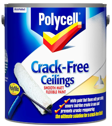
The vast majority of rooms have gone fine and are crack free, but the two largest rooms downstairs have quite a few hairline cracks at board edges. All edges were definitely scrim taped (Gyproc FibaTape Xtreme). The rooms are 6.4x4 and 10x4.6 and each plastered with Thistle MultiFinish in a single hit. The larger room was 15mm TE MR boards primed with Thistle BondIt. The other was 15mm SE WallBoard. It was a bit warm inside for this time of year 'on site', but something like 17C. Boards were attached to Gyplyner system (400c/c with brackets at 900c/c max.) and screwed at 200mm c/c or 150mm c/c at board edges. I don't think the cracks appeared in the first couple of days, but can't be certain. The door is sometimes left open as work is done letting in cold air, but the room temperature has pretty much stayed above 15C. I know about EasiFill/Paper Joint Tape/ EasiFill feathered in and sanded approach, but that would leave a slight hump and I made a huge effort to get the MF and plasterboard super flat. Has anyone tried the Crack Free paints? Two come to mind (linked below) but I'm worried that they are too good to be true. First hand experience would be very helpful. @nod have you encountered them or are they snake oil? The cracks are very fine. PolyCell Crack Free Ceiling Paint Zinsser Ceiling Pro 5-in-1 Some impressive pictures amongst the pictures of leaking tins.

-
Percolation Test - local suggestions near Edinburgh?
MortarThePoint replied to Meabh's topic in Rainwater, Guttering & SuDS
I dug it the hard way and it wasn't too bad 🙂 I'd say it's a good DIY job for anyone who enjoyed school science experiments -
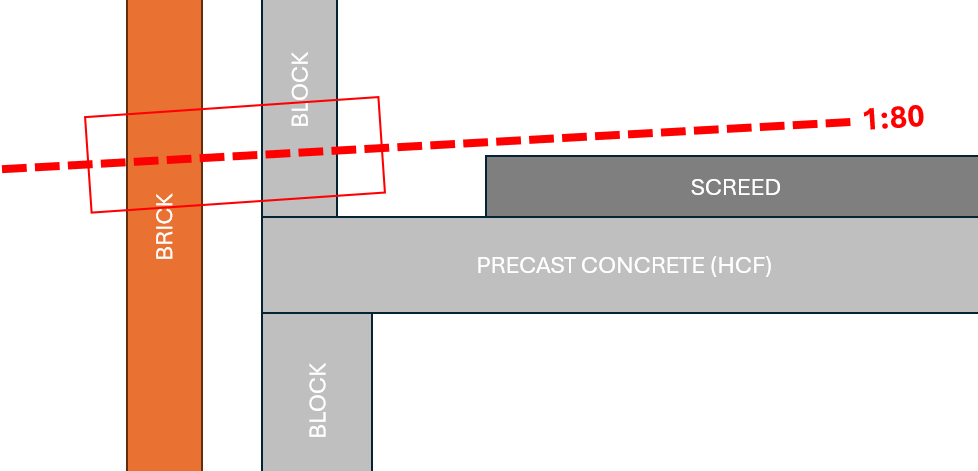
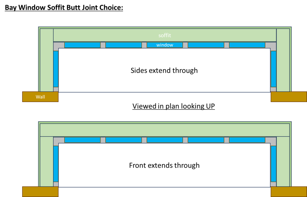
This is as much a roofing question as a window one I suppose. I have a rectangular bay window with 5 lights across the front and one at each return. Above the windows there is going to be about 45mm of painted timber and then the soffit leading out to the facia, guttering and roof structure. I don't want to do a mitre joint as it would be tricky and feels a bit fussy (shout if you think that's a mistake). That leaves two choices for a butt joint, both depicted below. Which is the better of these two options. I am leaning towards the top one as it will be harder to make out the joint when looking square on to the front of the house. What is the normal way to go here?
-
Some good thoughts
-
Partitions: Timbers studs Vs Metal C studs
MortarThePoint replied to MortarThePoint's topic in General Construction Issues
This link is now dead, but it can't be found by Googling ir761.pdf. I am attaching here anyway. Gypsum board walls: transmission loss data Halliwell, R. E.; Nightingale, T. R. T.; Warnock, A. C. C.; Birta, J. A. 20331556.pdf