MortarThePoint
-
Posts
2182 -
Joined
-
Last visited
Everything posted by MortarThePoint
-
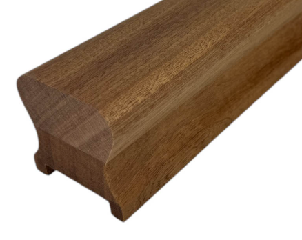
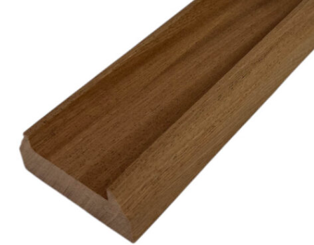
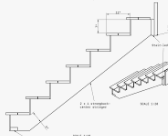
Along the landing, we're having Sapele hand rail and base rail with painted spindles in between and painted newel posts. The stair itself is an Open Stringer (or Cut Stringer) design and we're having Sapele treads with painted risers, stringer, spindles and newels. On the stair, the spindles have to be dowel fixed into the treads since there is no stringer top edge to put a base rail on. Every installation I see for spindles along a landing involves the glued packers, a blob of glue top and bottom on the spindles and perhaps some narrow pins through the edge of the base rail and hand rail into the spindles. Does anyone dowel their spindles into the base trail? Would that be excessive? I want to make sure I don't have an unpleasant surprise with the BCO if he says I should have added some fixing to the spindles. https://www.grosvenorstairs.co.uk/product/sapele-low-profile-handrail-44mm-x-60mm/ https://www.grosvenorstairs.co.uk/product/sapele-traditional-baserail-60mm-x-30mm/
-
Yes it's neat because you can have as many momentary action switches as you like connected to the coil and whichever switch is used, the light will change state.
-
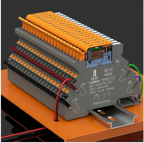
I like the approach of using latching relays. AnnualCost = (365*24/1000) x Duty x PowerWatts x ElectricityRate = 8.76 x Duty x PowerWatts x ElectricityRate Assuming that for a non-latching relay is PowerWatts = 0.2W, ElectricityRate = £0.20/kWh and the light is on for 3 hours per day (DUTY = 12.5%) that makes AnnualCost = 8.76 x 0.125 x 0.2 x 0.2 = £0.04 Unlikely to justify the latching relay on the basis of saved electricity. GEYA are not a brand I am familiar with, but their website looks like they know what they are doing: https://www.geya.net/ https://geya.store/products/gir-16a-1p-2p-230vac-110vdc-latching-relay?variant=48896365396248 £6.60 each on AliExpress GEYA also make slimline relay sockets for the HongFa 41F relay range: https://www.aliexpress.com/s/wiki-ssr/article/relay-hongfa https://www.geya.net/product/gr-h41f-lz-22mm-slim-relay-socket/ https://www.aliexpress.com/item/1005001437492488.html
-
Hongfa seem to be reasonable. They are stocked by RS (socket, relay) and Farnell (socket, relay) TEM (socket) https://www.hongfa.com/product/relay-socket/41F-Sockets https://source.hongfa.com//Api/DownloadPdf/201 Aliexpress are just a bit cheaper than most places for them if they aren't knockoffs which is hopefully unlikely. It would be good is LCSC did them A 20way solution with a GPIO buffer would probably run to 2*£30 + £20 = £80 which shows the good value of the Waveshare options not to mention the really cheap ones.
-
Nice: https://thepihut.com/products/modbus-rtu-32-channel-relay-module https://www.waveshare.com/wiki/Modbus_RTU_Relay_32CH Waveshare are normally pretty good. I can't see any CE mark statement though. Pros: Cheap: £2 / channel -> £3 / channel with RS485 converter and PSU OK ON power: 11.7W / 32 = 366mW / channel Reputable: medium/high though question on CE mark Well supported Cons: It does have significant single points of failure though. I'll always be able to get DIN mounted relays. CE mark? I like Modbus / RS485 and have used it in some fun applications but it's overkill for my setup since they will be co-located. That said, it's a quick solution to the interfacing challenge. Waveshare make some other interesting items: 8-Channel ESP32-S3 WiFi Relay Module with RS485 (PoE Option) £48 30-Channel Ethernet Relay Module with PoE £67 sold out 16-Channel Modbus Ethernet Relay Module £53
-
They'll have something to remember me by when they are sat in the dark 🤣 Have have wired the house so that it can be converted to a conventional switch based one by only making changes near the consumer unit. That said, it would be good to have the type of relay that has a switch override so that all could be left switched on and then smart bulbs used instead.
-
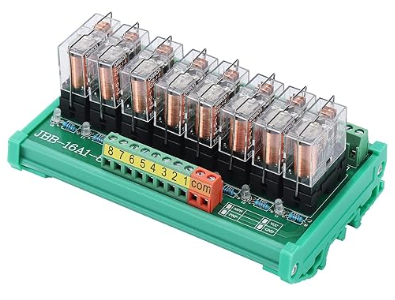
The main issue with the individual DIN rail mounted relays is the need for control buffering since the coil powers are too high for GPIO control. Nice servicability though These are tempting: They appear to use HF41F relays: https://static.rapidonline.com/pdf/507532_da_en_01.pdf Those 5V relays have a 147R coil resistance and 170mW coil power. 34mA is too much for unbuffered GPIO use though. These look really nice, but the coil power (0.9W) is unacceptable:

-
It's the 'roll your own' desire. Yes I could get 5 or 6 Shelly 3 channel relays for £400, but I like making things and can also be outside any walled gardens. The 16channel PCB for £11 with a £9 Raspberry Pi saves quite a bit too. A bit too much for my liking
-
DIN rail would arguably look more professional I agree, but ultimately you could still have dubious DIN rail parts These look nice, but the CE logo looks more like the old China Export trick. There are also things like this that claim to use Omron relays:


-
I want to have my first floor lights all automated by a central control box (star wiring arrangement, already laid to allow this). At the heart of this I need a relay control PCB which should be at least 16way. The day job gives me the skills to design such a PCB, but there are some off-the-shelf options and a variety of prices and they would come with CE marking of equally variable legitimacy. I could power the whle thing from a mains plug in which case it would be outside of the scope of the Sparkie's signoff, but I want his blessing and he's keen to see a CE mark on it. I want to control the PCB with either a Raspberry Pi Zero or ESP32 which I am happy configuring and running a local webserver from. The Raspberry Pi would allow a USB connection to the relay PCB (as would some ESP32 boards), but I would prefer to have something less protocol stack sensitive like I2C or UART. Does anyone have a good recommendation of suitable relay PCBs. I have seen things ranging from White Wing £175 to Amazon / Aliexpress <£11. The main thing I want to be able to trust is the relays themselves since that's where the mains is. I think all the PCBs have optical isolators, but I wouldn't handle the RPi / ESP32 when it's got mains anyway.
-
Secure Clip Glazing Systems (Dry Glazing Systems)
MortarThePoint replied to MortarThePoint's topic in Windows & Glazing
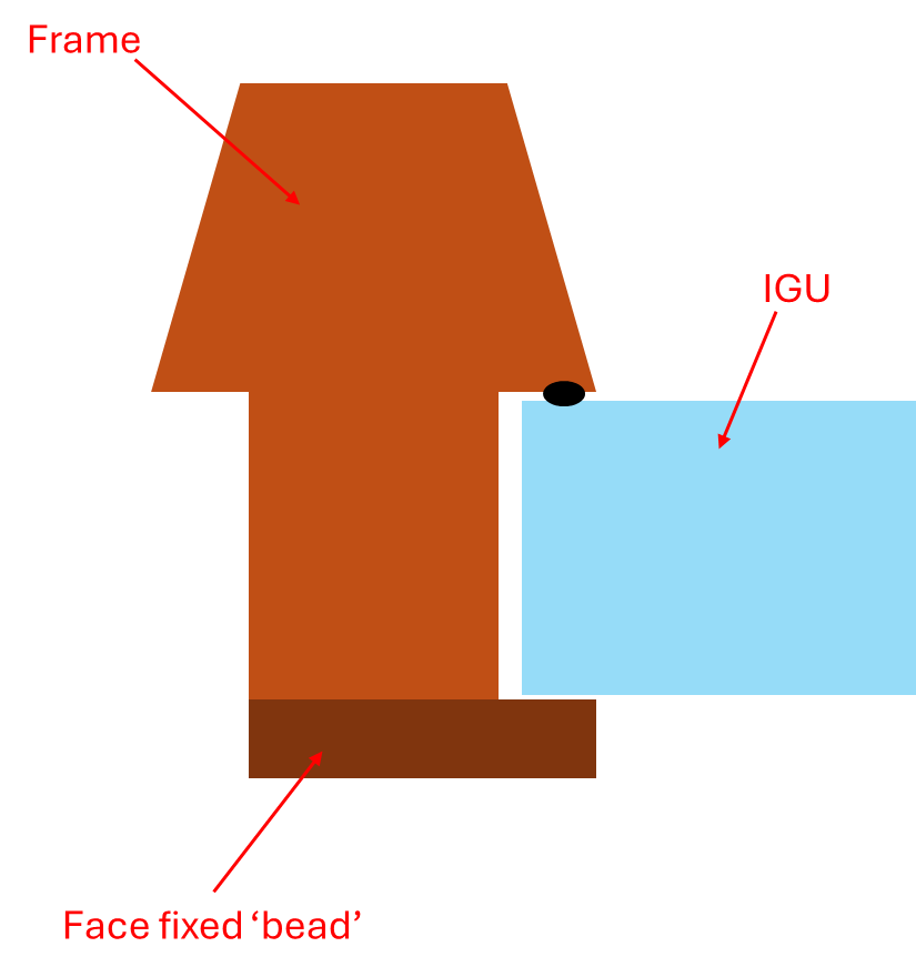
Thanks Craig. A difficulty I have is that the frame I am using is designed around a 44mm thick door and consequently the recesses are 47mm deep. There is no room to fit a bead in with a triple glazing unit. What I was thinking of doing was adding a timber piece (dark brown ) to the back of the frame that extends over the edge of the glazing panel and effectively forms the bead. Unlike pins in a normal bead scenario which are loaded perpendicular to their length, any fixings in that additional piece would be loaded along their length, so pins would pull out. I could use screws, but they would end up visible which I don't want (oak finish). The clips seem like a good solution since the bead ends up just being cosmetic as I understand it. I realise I could extend the frame by gluing timber on which is no wider that the frame already is and then use a conventional timber bead, but that would mean I would have to extend the frame more. I expect a suitable bead would be at least 15mm whereas I can have a much thinner back piece (dark brown) if it's only cosmetic and clips are doing the work of holding the panel. It's shown below as 12mm, but could go thinner.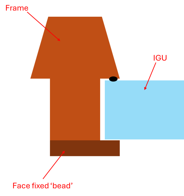
-
Secure Clip Glazing Systems (Dry Glazing Systems)
MortarThePoint replied to MortarThePoint's topic in Windows & Glazing
@craig Have you come across these clips before? Any thoughts? -
Should top of Drainage Chambers be Level ?
MortarThePoint replied to Spinny's topic in Waste & Sewerage
I don't want to get flamed for it, but some manufacturers say that chambers (mini ones) don't need to be installed with a fall. I install them with a fall though. In my experience (limited) the chamber bottom and rim are parallel so you can check wall at the top. -
Secure Clip Glazing Systems (Dry Glazing Systems)
MortarThePoint posted a topic in Windows & Glazing
I'm making a custom door with sidelights and want to use a secure clip glazing system to hold the glazing panels in place. The panels are 44mm thick triple glazed ones, so that's a bit unusual for the clip systems I think. I have seen two systems online: GT Securi-Clip [link] - apparently PAS 24 Reddiseals Easy-Clip [link] - now discontinued unfortunately Has anyone any experience with these? They seem to top out at 28mm glazing thickness, but I see no reason I couldn't use a 28mm one offset the correct amount as long as I supported the glazing unit on suitably wide packers. -
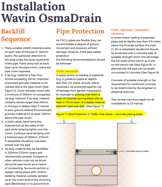
Osma (Wavin) advice on protecting shallow pipes. I've put 100mm over the pipe crown everywhere, so can use slabs where less than 600mm and just backfill (inc. 40mm stone) elsewhere.

-
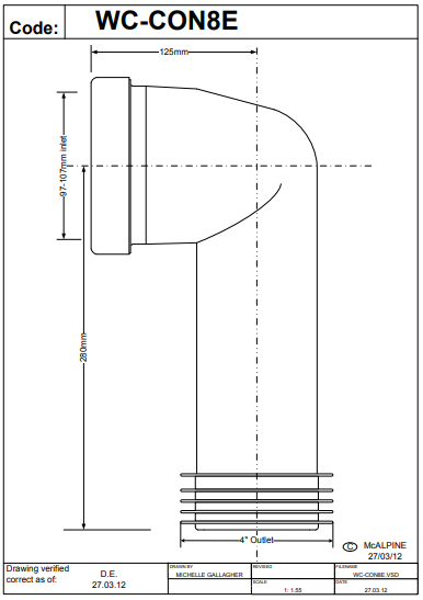
It is a tiny amount and I think there is always going to be a little bit of liquid left against the seal by the nature of the fact that the MAC8E's pipe section is a narrower ID than the Spigot's OD. Like so much of this game, it's really annoying when you've worked hard to get it right and then the tolerances conspire against you. I think you're right, time to crack open a beer.

-
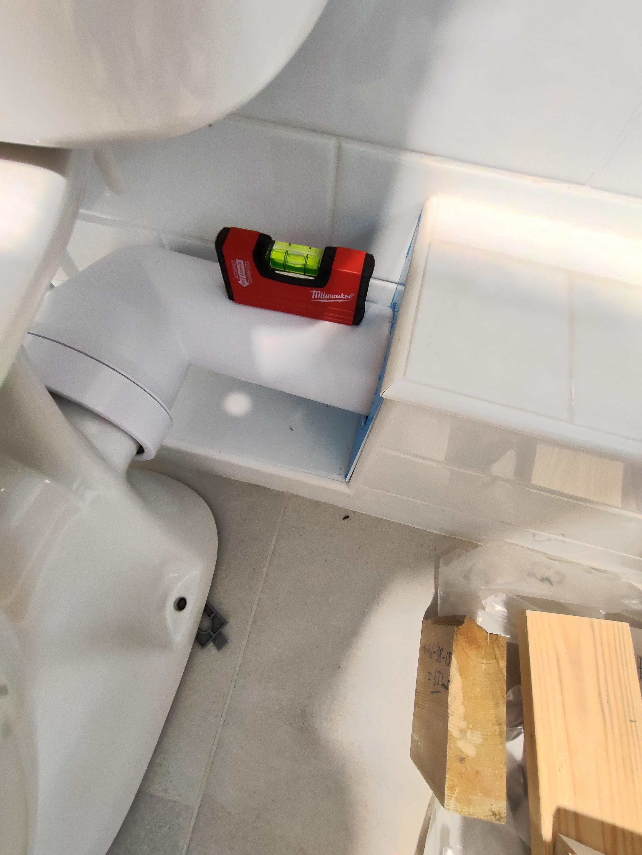
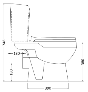
By measuring the height (107mm) above tile to the underside of the MAC-8E's 'trumpet spigot flange' and based on a crude measurement of the MAC-8E drawing's 'trumpet spigot flange' O.D. (136mm) I get that the spigot height of this toilet is actually 175mm (107 + (136/2)) not the 180mm it's supposed to be. That's the main route of my problem. The tiling is also likely a tad thinner than expected, but the spigot dimension is the main issue.
-
I guess hunting around for a toilet with a 190mm spigot height (or 185mm minimum).
-
Actually, thinking about it there is often going to be some water there since the toilet spigot is larger diameter than the pipe section
-
May mean I have some waste water permanently sat in the connector against the seal to the toilet pan. Isn't that a concern?
-
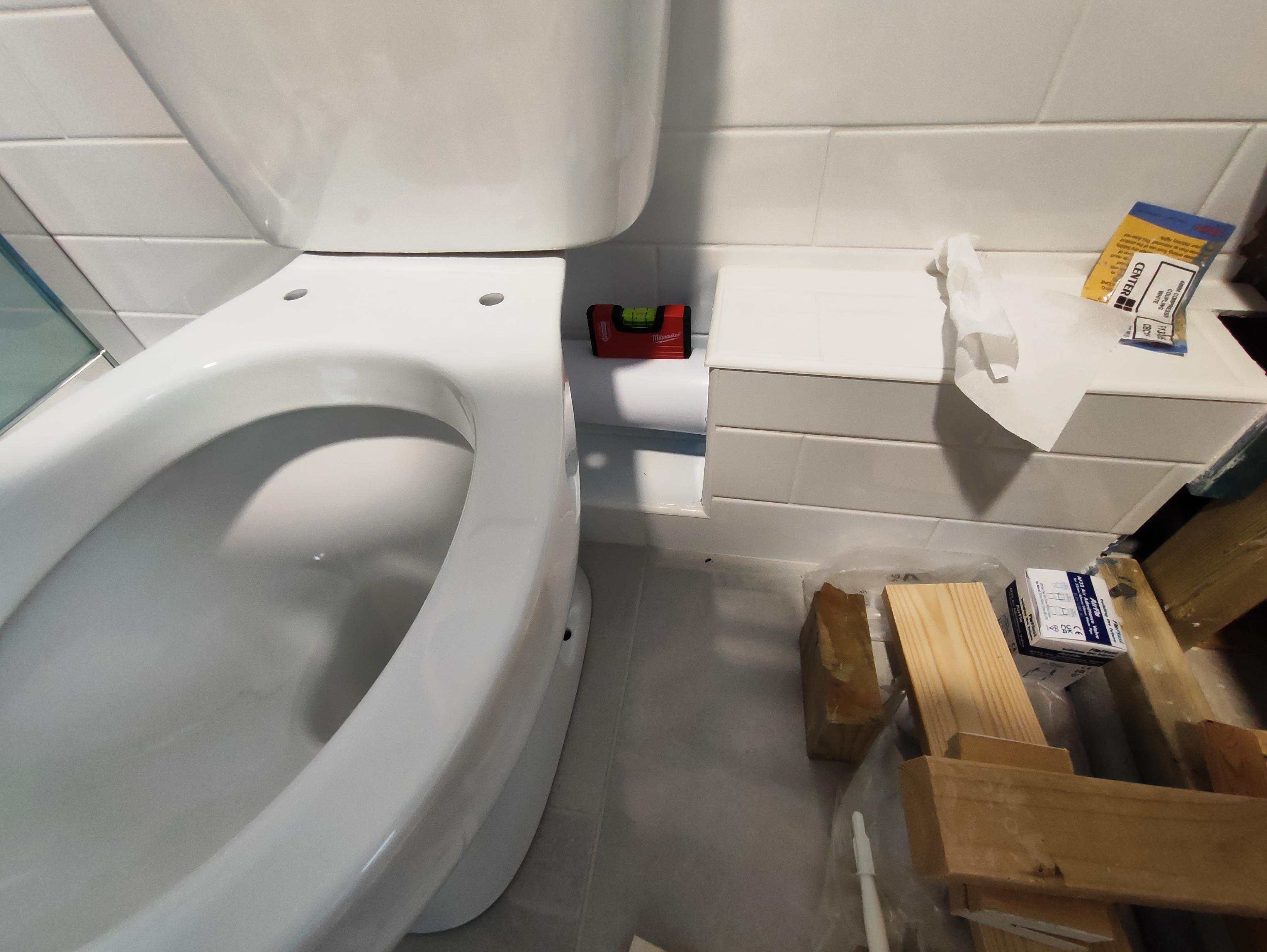
I haven't drilled any holes for the toilet screws yet so that wouldn't be an issue. I do have some spare tiles. Are you thinking I could create a low platform for the toilet to sit on?
-
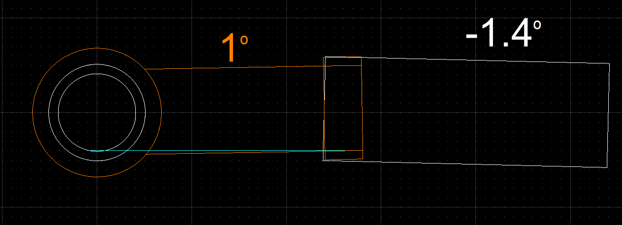
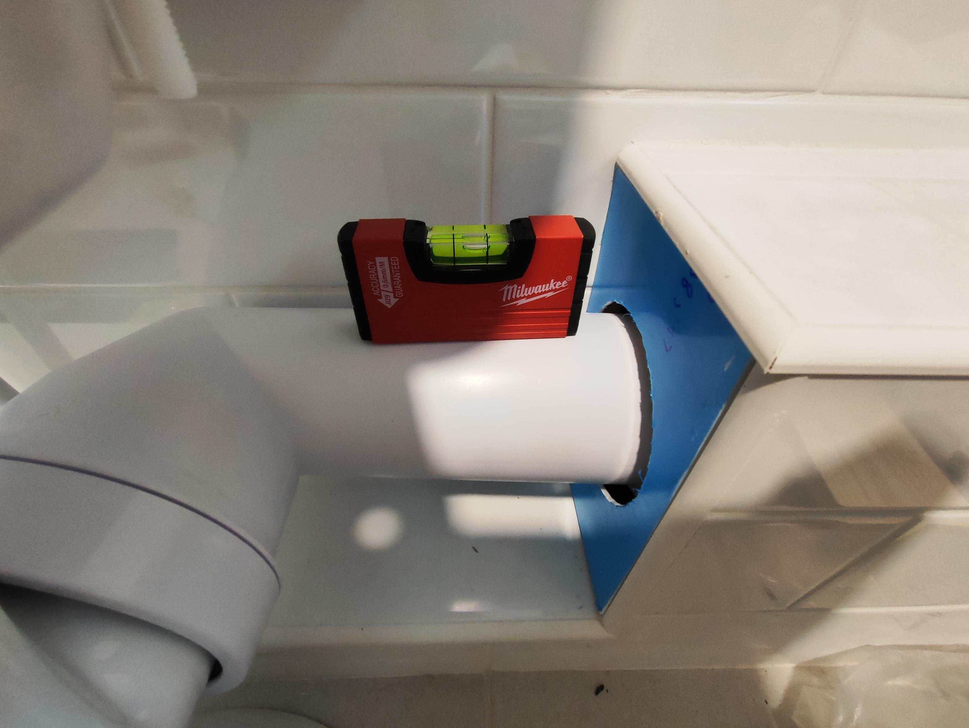
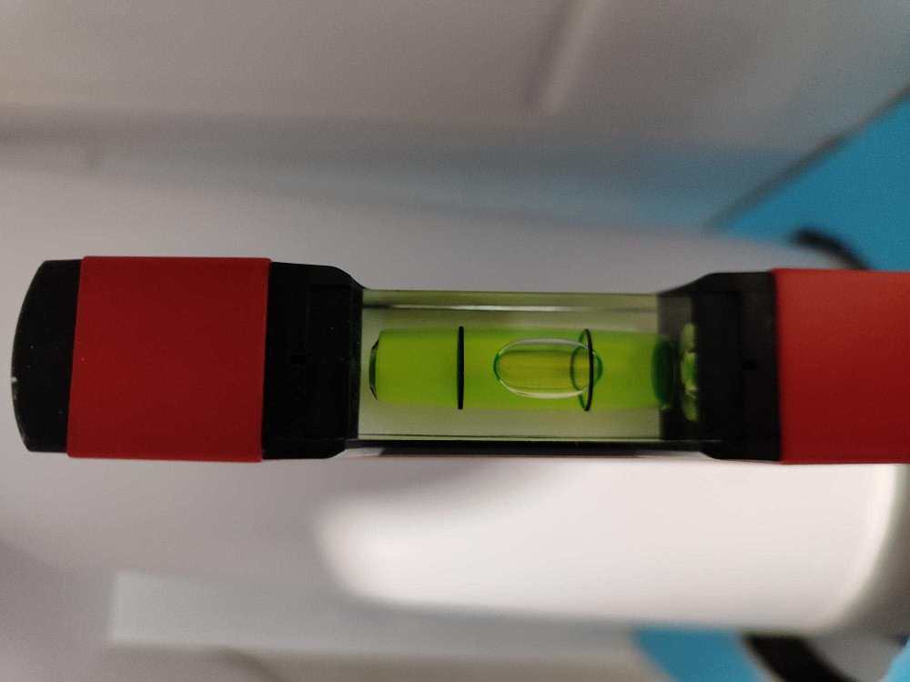
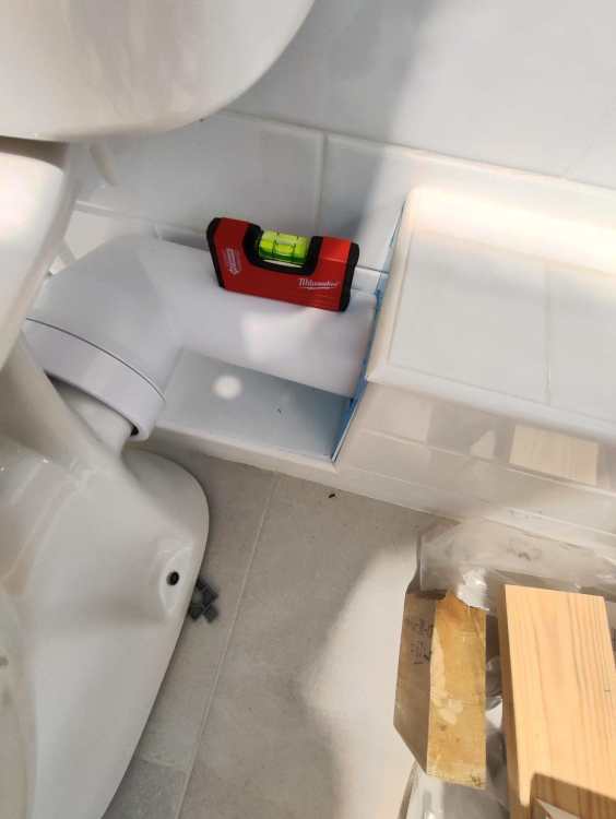
I'm using a McAlpine CON8E and it connects up nicely except my soil pipe is too high relative to the tiled surface meaning the connector's pipe section doesn't have a fall. In fact it slopes slightly the wrong way. If I raise the toilet up on 5mm packers, this pipe section is level. Ideally I'd want a fall of about 1:40, which would mean having the toilet 10mm above the tile. I can't change the height of the soil pipe as it is all boxed in so I'm wondering what to do? I think the spigot on the toilet is lower than it says in its dimension drawing (180mm) and the tile build-up is thinner. I've attached some pictures of the situation and then a single picture of it with 5mm packers under the toilet.


-
Insulated hot and cold water pipes?
MortarThePoint replied to Alan Ambrose's topic in General Plumbing
Probably still less wasteful than whizzing hot water round a circulation system all day long -
Insulated hot and cold water pipes?
MortarThePoint replied to Alan Ambrose's topic in General Plumbing
The concern with uninsulated cold pipes is condensation forming on them. I think a 15mm pipe is something like a litre per 10m of run. A shower at 6L/min would clear 10m of pipe in 10s. I've even wondered about the benefits of a circulatory hot system Vs just filling the toilet cistern from the hot supply. The cistern fill would clear the pipe of the cold water before the basin tap get turned on. Insulating hot pipes for between uses is pointless in my mind. Others may have experience to the contrary though. Also, regs require it. -
Loads of colours available to add to white cement. White cement is more expensive (2x I think) but small difference Vs labour costs. If achieving the colour using an additive rather than sand, check how consistent it will be. The brickie's labourer may vary the dose and that could create banding. There is an expensive new college building I see in Cambridge and it's a dogs dinner due to this issue I think. You can influence the colour a lot with choice of sand and that should be more consistent as long as everyone understands. I'd be cautious of going the lime route. Fewer brickies have experience with it and it can be less tolerant (e.g. temperature). In the right hands it's great and looks brilliant though.