Onoff
-
Posts
21127 -
Joined
-
Last visited
-
Days Won
206
Everything posted by Onoff
-
I've been given two old sheds. The first one is I think 8'x6 (or is it 10'x8'?)'. I dug out the sloping site, did a concrete base, built a dwarf wall with some stocks dating to 1863 along the front, raised the shed, made a new door etc: Tbh, WTF did I bother? Next to huge overhanging conifers it's too small and damp. I royally effed up to by experimenting with DIY insulation.....straight onto the wood: Result? Damper than a damp thing. All the T&G is fecked and opening up on the outside. And too small. The other shed is just sitting under tarps where it will probably stay. A bit bigger, flat roof, but needs more work to repair. I should have converted both to firewood and sold it in bags down at the gate. Then put the cash towards something like Barney has done!
-
No tape or anything on it.....yet! Just backed it off in case it's maybe not in the stopcock square. A pig squeezing in behind the WC too: Maybe I need to wiggle it so its square as I tighten it up. Think when I measured the incoming pressure a while back it was circa 9 bar so this needs to be done properly!
-
Bugger! The 25mm MDPE to the stopcock is leaking a tad. Yes there's an insert in the pipe, yes the olive (metal) that came with the stopcock is on the pipe. Doing it up and it's starting to squeak.....
-
And the crowd goes wild as Onoff finishes something.....(nearly)! A little off piste to the suggestions but it puts the isolators in line. Fascinating watching the PRV going up and down! Cheers all. EDIT: Just got to screw the tap on outside.
-
Erm....bit of both tbh!
-
Erm.....you know my "temporary"! Tbh probably won't use the spare Geberit frame here or at least just yet. This WC is at the end of a narrow corridor that's been formed by hiving off a strip from the downstairs bedroom. Its not been done well either to my mind. Long term plan is to widen the corridor slightly and make an en suite shower room. So although the WC will be roughly where it is now it won't be exact. Back to me connecting the flexis like this...why not? Is it that the rubber washer doesn't seat properly on the compression fitting faces? Cheers EDIT: What was I thinking! I'll ditch this flexi and fit a compression one with short bits of pipe in the fittings.
-
Bit the bullet and went with a flexi. I assume they're OK straight into the compression T / isolator valve. Btw the isolators are Pegler half decent ones. I'll sort the outside tap tomorrow. Bit miffed with the PRV gauge as its all plastic rather than brass as shown on the Sfix site. Needed some PTFE tape in the threads to get it tight. All nutted up now so a bit straighter.
-
Lucky I don't live in a draughty old house full of holes with oil fired CH..... .....Oh sh**, I do! Filled up when it was cheap thankfully.
-
My first plan was to drill at 20mm, then slip in a length of pvc electrical conduit and run the 15mm copper thru that. I HAVE taken on board what you said that if you drill too big a hole it can cause probs on the outside for the 3 screws in the flange plate. I reckon though that the conduit would work improving the angle and still allowing screwing. With the Cuprofit, from memory they allow for a bit of an angle.
-
The bib tap..... I drilled thru the wall with an 18mm bit. Might have gone thru at a bit too much of an angle tbh. The tap where it screws into the wall plate thing was surprisingly loose and had taken copious ammounts of PTFE tape to get tight. I'll wrap the pipe in tape as has been said. You can see the pipe coming thru the wall. But will I get away with a Cupro, push fit elbow as opposed to a solder ring fitting? Be easier to lineo up as I could just rotate it!
-
I spent ages on that saddle bend! It'll look lost
-
I'd do any soldering first then "spring" it in. That bottom 15mm pipe off to the basin is as floppy as.
-
Cheers. The existing one has a red fibre washer in.
-
Cheers. Effing fiddly this plumbing lark! Not sure what size the "tap" connector is on the bottom of the cistern. It measures 21mm across the threads and a 24mm spanner fits? 15mm x 1/2" or 15mm x 3/4"? Thinking I might just be able to get an end feed, solder ring tap connector on and then a tee underneath.
-
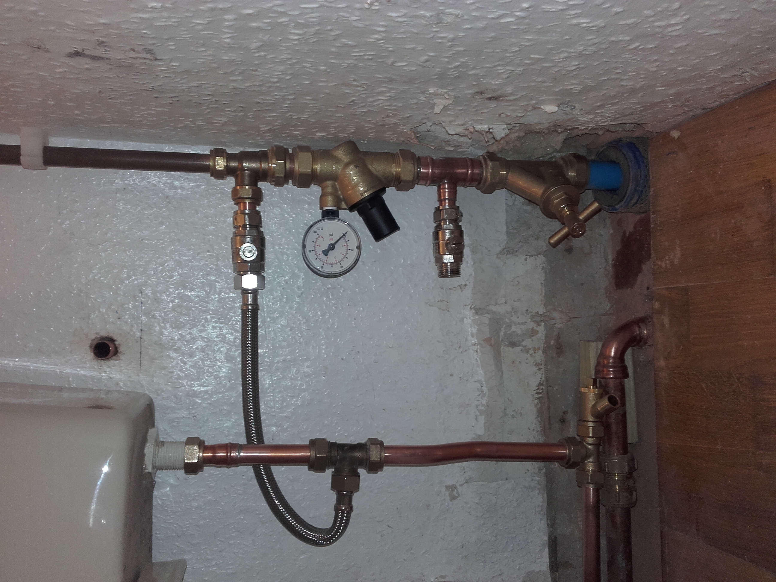
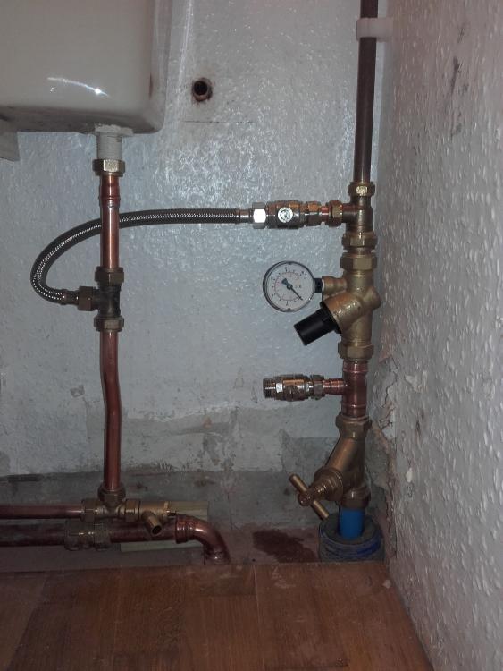
Hmm... Putting this lot in and tbh I thought this might be an issue. On the right, first then I've the stop cock on the MDPE, then a tee off to the outside tap via an isolator. Next comes the PRV with a tee above to feed the cistern and cloak basin. BUT.....the horizontal tee off to the cistern puts the 15mm pipe too high to practically connect to the cistern and then drop to the tee with the drain dock on: At the mo I've the chrome tap connector on the cistern pipe. Any suggestions? Cheers
-
1) How about a brick shed? 2) How much do you drink? http://inhabitat.com/heineken-wobo-the-brick-that-holds-beer/
-

Stage 1 Is Very Nearly Complete :)
Onoff replied to Construction Channel's topic in General Self Build & DIY Discussion
Looks great, like it's always been there! 4 months? That's overnight by my standards of doing anything! -
I'm going to make a shed out of pallets.....
Onoff replied to ProDave's topic in General Self Build & DIY Discussion
Great thread. My nephew is badgering me to help with his pallet shed which I've designed but we've yet to start. Tbh this side of next Spring he's got no chance of me helping unless I fancy a break from my stuff. Thinking to tell him to stack the pallets and sling a tarp over it! Those vertical planks Dave, won't horizontal rain come through the gaps? -
Let's be honest you could squirt expanding foam in first.
-
Expanding Foam - an effective weather seal?
Onoff replied to Stones's topic in General Construction Issues
Ref the use of foam as a scaffold I work closely on occasion with guys fitting commercial glazing. They will pack gaps with grey, cylindrical foam strip - think pipe lagging without a hole up the middle. Comes in various diameters. It gets forced in then siliconed over the top. Some gaps are SO wide I've seen them simply cut the top of the mastic tube! They frequently use too, a torch on, embossed aluminium "felt" they call Solar Shield in gutter details etc. -
Expanding Foam - an effective weather seal?
Onoff replied to Stones's topic in General Construction Issues
And wasps & bees chew through as do birds. -
Magic or Wiska Gel maybe?
-
Expanding Foam - an effective weather seal?
Onoff replied to Stones's topic in General Construction Issues
Seen a few basements in commercial buildings where they've tried to seal around pipe and cable entries with it. Water just pi$$es in. Might be a water table/pressure thing but it's failed every time. -
Think my first ever pipe cutter was Wickes, then a couple of Forge Steel ones and the odd really naff pound shop one! A bad workman etc.....
-
I do follow up with wire wool tbh but am fastidious about having no burrs. Knife is so much better than this 3 bladed Monument thing. I find with the knife I can take off the burr in almost a continuous strip of swarf.