
Radian
-
Posts
2586 -
Joined
-
Last visited
-
Days Won
15
Everything posted by Radian
-
I bet the car had a nice view out of that bay window. ⁉️
-
I wouldn't think a mouse would just leave it there, not if it went to all that hassle of climbing there. More like a cacheing behaviour. Crows?
-

Cavity wall between garage and house insulation
Radian replied to SteveMack's topic in Heat Insulation
Have a read through what thegreenage say about EPS. The beads are naturally water repellent and even in a 50mm cavity, there will be dozens between the inner and outer leaves so water has to transfer around each sphere to make the journey across. It's like having a series of drip mouldings and one of those is usually enough to stop water transferring horizontally. Another analogy is thatch. Each reed in the bundle directs the rain down the length of the roof an not into the roof. It's one of those phenomena where statistics provide you with the goods. -
Cavity wall between garage and house insulation
Radian replied to SteveMack's topic in Heat Insulation
Did whoever told you that do a proper survey and were they considering a variety of different insulation materials available? I sincerely doubt it. Most contractors have only one kind of insulation material e.g. blown-in mineral fibre which is highly unsuitable for exposed brickwork. We had a survey done and despite being less than a mile from the sea, in exposure zone 1, there was no issue when using EPS beads. This is because the beads do not conduct water across the cavity but do allow enough air to circulate behind the back of the outer leaf to assist with drying out. Have a serious look into it, the heat loss through an empty cavity can easily be halved by filling with beads. Beware the beads on Ebay may well have met 1988 fire regulations, but for what purpose? Buildings or furnishings - and 1988! Today's EPS fill is graphite coated for flame retardancy. -
I could have told you this would happen some day....
Radian replied to ProDave's topic in General Alternative Energy Issues
Also look closely at the source. Shouty MAGA conservatives. -
Cavity wall between garage and house insulation
Radian replied to SteveMack's topic in Heat Insulation
Depends on the proposed fill material and the condition of the cavity down at the foundation level. I've got some standing water at the bottom of my cavities at certain times of the year and I wouldn't want any fibre based insulation dunked in it. On the other hand, no problem for EPS beads. I assume your garage has a trussed roof which is why you have access to the top of the cavity? The temptation here might be to fill the cavity with a bulk load of furniture-grade poly beads. The obvious issue is fire safety. I'm wondering if this cavity is empty, might there be others that are also unfilled? - in which case contracting a company to inject all empty cavities would certainly be worth while. If this was the case, your stated scheme to close the cavity should still be done and before you get the cavities injected! -
I've recently had a couple of A2A units installed and 2 guys spent a day and a half working hard to do it. I don't see where your two hours as being particularly realistic.
-
1960s Warm Air Heating Upgrade to Air to Air ASHP
Radian replied to RenewableNeil's topic in Introduce Yourself
Blimey. The pilot alone on that must be costing you a bit. I'm a recent convert to A2A on account of its ability to give me space heating for the absolute minimum energy cost. But that's using mini-splits so it's ductless. Mitsubishi seem to be into ducted A2A heat pumps systems: -
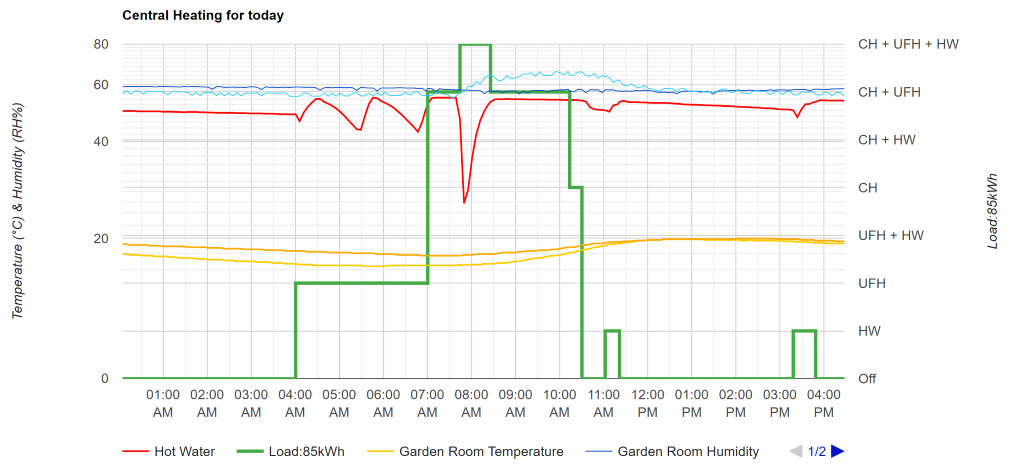
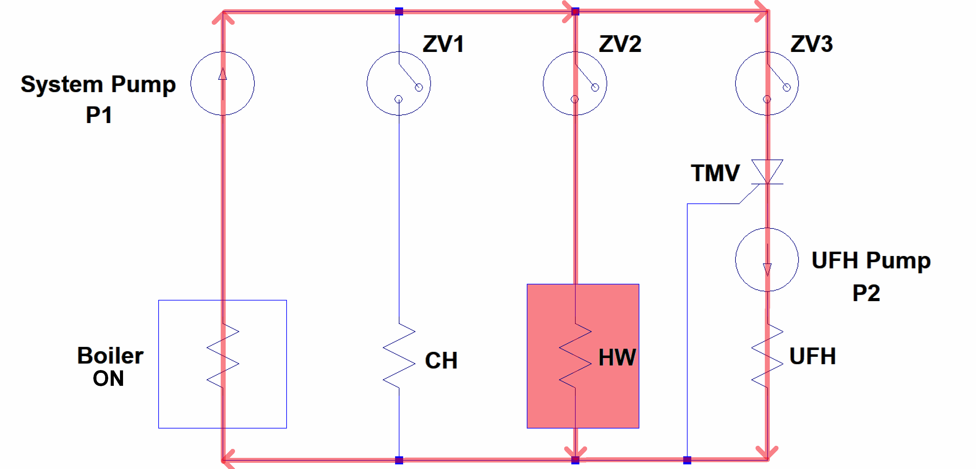
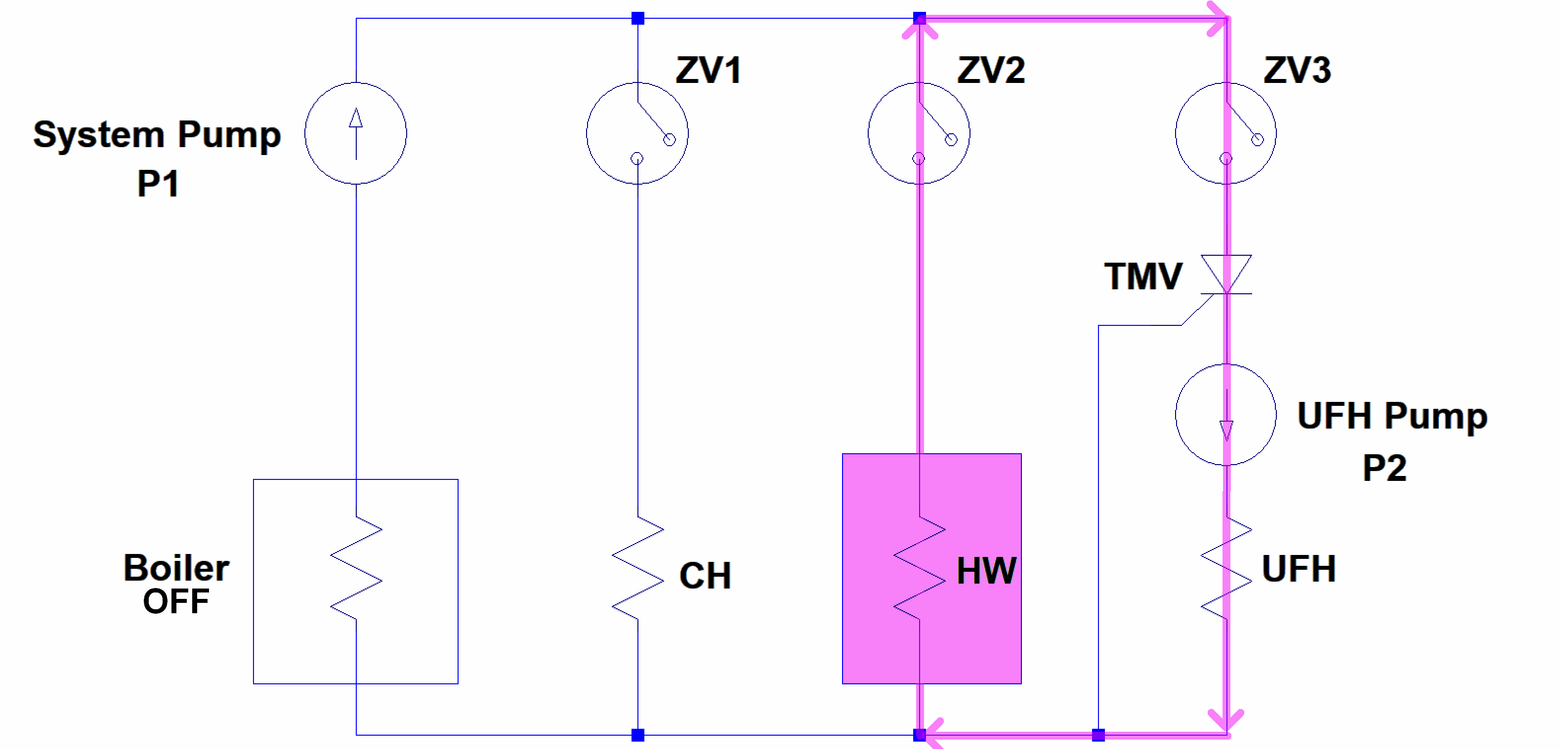
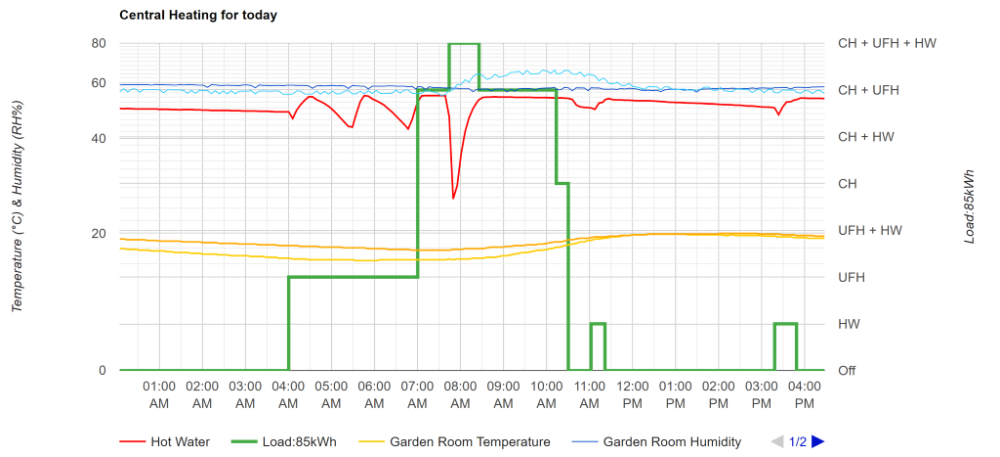
Well, this one's a keeper. Saved an awful lot of extra plumbing and finding somewhere for the buffer tank. Data: At 4AM when the night set-back for the UFH ends, the boiler starts heating the UFH loop to 45oC (via a TMV) and also brings the HW cylinder temperature up to 55oC as per this schematic: Then the boiler goes off and the HW is circulated around the cylinder coil and UFH loop until the HW drops below 45oC. it will continue to cycle up and down while the UFH demand is present: When the floor is cold, the on/of ratio is between 1/3 and 1/5 when warm which, with a 10kW min boiler input, is effectively further modulating down to between 3.3kW and 2kW respectively. The only downside I can think of is that the flow through the boiler, when off, is only restricted by the de-energised system pump. If I find that this is too lossy, I suppose I could replace ZV2 with a three-way valve. All the losses in pipework are within the house so I don't see it as a big issue.


-
I've had good results fitting a draught sealing strip around the stop bead of a fire door to garage. Stick-on compression seals are best if you can set the hinges to give enough space. I did this assuming that as it didn't interfere with the intumescent strip, it would be OK with BC.
-
Oh yeah, all ours have 50mm long screws to reach the back boxes.🙄 Apart from the near impossibility of finding the tapped holes at that sort of depth, the 50mm screws must have been the only long ones available as some bottom out at the back of the box. Either that or the sparks was a sadist. I didn't understand that this was happening until the threaded tabs started breaking off as I kept on tightening the screws.
-
Was that really in the early 90's? Would have said more like £50K - or maybe it was in Park Street or Littlemoor?
-
Good spot. I'd missed that 'right hand' was referring to the MCB, not the box on the right. An intermittent short would be an unlikely but serious fault, however there's another possibility. Compressors can draw huge spikes of current when starting. My old fridge could pull 8A for under a second, likely more as this was recorded with a 1s sample rate. Is the fridge somewhat old?
-
1200mm wide block wall layout query
Radian replied to Capable Noob's topic in Bricklaying, Blockwork & Mortar
What about alternating 440.300.440 with 150.440.440.150? In practice, splitting a 440 into 3 and using those pieces would, with the extra mortar gap, just make 1200. -
You might be interested in this topic if you've not seen it before: It's quite possible that the trip happens when your fridge/freezer cycles the compressor on or off. Compressors can produce transients and the presence of any digital kit on standby may be bypassing a spike to earth, or as in my case, a multi-socket adaptor with built-in surge protection. The problem with these is that surges are bypassed to earth causing the RCD to trip.
-
I would just reiterate the dimension of how much a given type of system relies on the skill of the installer. Foam injection systems offer the maximum available thermal performance but require a high degree of professionalism to make sure the mixture is applied correctly. The closed cell variety also has a big impact on the breathability of the structure hence the essential need for a condensation analysis which will probably mandate installing a new, whole house, ventilation system. As I said, the EPS bead systems are idiot proof, do not interfere with the breathability of the structure, are cheap and perform reasonably well.
-
It may well be all of the above. It's definitely been studied in use as a flame retardant but I've yet to see any studies on the other properties.
-
I was sat on the fence for ages too. Then Vlad the Invader made up my mind for me. I researched the shit out of it and concluded it was the safest bet of all the competing systems. Being about one mile from the sea in exposure zone one, I wouldn't take any chances. Early days yet but no problems have shown up yet. And boy have we had some gales and driving rain since it was done!
-
Good question. I've bee trying to figure out if it's a buffer to prevent plasticiser leaching, but all I could find was mention of it being used as a flame retardant. Probably came out as more insulating than uncoated within experimental error bars and got snatched-up by marketing. Dunno.
-
SuperBead has a declared thermal conductivity of 0.033 W/mK which is exactly what I used to calculate your cavity wall loss after insulation (same as mine). They are graphite coated which makes them perform a little better than uncoated white beads. They say it's injected with a binder, which is good as it means the beads stay in position. Yes, they seem fine. The installation company should send a surveyor to you first to establish the suitability of your property. If you decide on this, make sure you're present when the survey is done and sit on their shoulder - be nosey and ask questions. They should drill a hole in each elevation and put a borescope (camera) into the cavity to check its condition.
-
You are quite right to be wary, but EPS beads are generally considered to be safe. Unlike fibre based products they don't wick water, don't compact over time and still allow a degree of airflow for drying out brickwork. Being spherical beads, they fill cavities very effectively with fewer injection holes. This makes them a good choice as the contractors that do the work are usually idiots - so an idiot proof system the best one to choose. Have a look at this energy saving trust document So a U-value of 0.14W/m2K whereas your empty cavity walls lose nearly eighteen times as much heat.
-
Any particular reason? If it's brick outer leaf, 50mm cavity and concrete block inner leaf with solid plaster then you're looking at a U-value of at least 2.5W/(m²K) in a 4-bed detached so typicaly 200m2 floor area, 140m2 wall area. Windows and doors may average out about the same if not airtight so a constant 3.5kw loss for a 10oC inside/outside difference. Insulating the cavity with blown-in EPS beads would take the losses through the walls down to around 0.5W/(m²K) i.e. 700W although the windows would then probably be the poorest performing part. Shame to loose the benefit of your good loft insulation. I assume 400mm rockwool?
-
It's a 160 Litre stainless-steel vented type with a single indirect heating coil. The minimum HW temperature setpoint is adjusted to meet our needs from the various mixer taps. Early days yet but no complaints so far. I wish. Anything I shave off the boiler flow temperature also has to come off the maximum HW cylinder set-point. I've found empirically that there has to be a 10oC difference between HW set-point and flow temperature to ensure that the boiler doesn't go from its lowest modulating power level into bang-bang control as the temperature nears the set-point. I think this is potentially just as wasteful as having a boiler return in the mid 50's but I can't say why exactly... ...I started out this experiment because the boiler was short cycling and I kept reading people saying this was bad. It certainly puts an additional strain on the boiler.
-
Let me start by saying that I'm posting this in Boffin's Corner because it's about an experiment that curiosity has driven me to try out. But it's probably not something the professional plumbers around here would endorse. Nevertheless, this is what I'm trying: The issue I'm addressing is running a small, single zone UFH loop using a 30kW system boiler that only has a 3:1 modulation capability. The UFH loop only requires around 2 kW so, in the absence of any other loads, the boiler inevitably short cycles. A classic case for using a buffer... that I never managed to get round to installing. However, due to an accidental failure of my HW cylinder zone valve (stuck in the open position) I noticed an interesting behaviour... With demand coming from the UFH room thermostat, both the HW and UFH loop were being heated - with HW reaching an uncontrolled maximum - while the boiler demand was being controlled solely by the UFH. What was interesting was how, when the UFH demand was satisfied, the UFH circulating pump continued circulating through the HW cylinder coil and the room temperature continued to rise while the HW cylinder fell. Only when the HW temperature fell below the automatic UFH pump threshold did it stop circulating. The HW cylinder was acting as a buffer. So thinks me: I have thermostatic mixer valves and taps so a fluctuating HW cylinder temperature will not be noticed, so why not deliberately ping-pong the HW in and out of the cylinder when the UFH was required? Given that I have full control of every central heating component in a Python script running on a Raspberry Pi, I have just set this up with a minimum buffer temperature of 42oC and maximum of 52oC and it seems to work like a charm. In a typical cycle, the boiler now runs continuously for 15 minutes while raising the temperature in the HW cylinder and then shuts off for 60 minutes while the HW is depleted in the UFH loop. This gives a final ratio of 1/3x4 or 2.5kW Can anyone see a hidden problem?
-
That's something I rarely see being considered here. Maybe the majority of BH contributors are retired 😁 But seriously, given the best way to run UFH is constant room temperature and the response time is in the order of hours, what if anything can be done to minimise heating costs with such an occupation pattern?