
BotusBuild
-
Posts
1379 -
Joined
-
Last visited
-
Days Won
10
Everything posted by BotusBuild
-
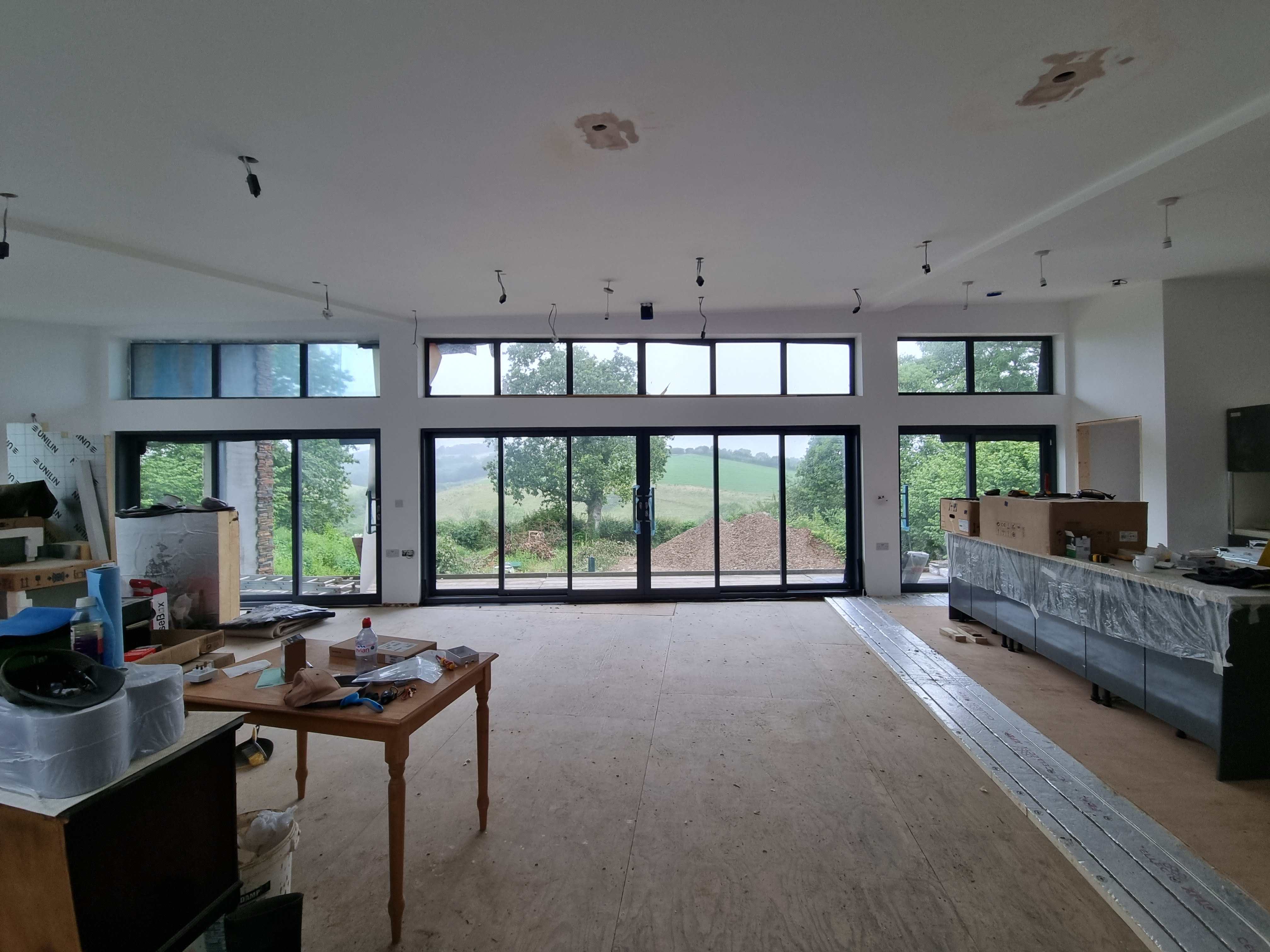
Like my foundation slab, that on three sides has retaining walls, your slab is part of the strength of the retaining wall (although not shown i suspect there is rebar and mesh that connects around the bottom corner of the new wall and into the slab). So, the slab has to be there AFAI can see. Your final finish will need to have a gradient on it anyway and you can make that gradient be away from the door opening. Render should not go all the way to the ground to avoid splash back
-
Bad roofing job: how should I proceed?
BotusBuild replied to David001's topic in Roofing, Tiling & Slating
Exactly what @Mr Punter says above -
Bad roofing job: how should I proceed?
BotusBuild replied to David001's topic in Roofing, Tiling & Slating
David, I fear you may have already paid them. If so, save your sanity, and get a(nother?) recommendation from someone locally to completely redo this. Hope you can find someone to sort this out for you -
Which way up should roofing membrane lie?
BotusBuild replied to David001's topic in Roofing, Tiling & Slating
I don't think the vapour barrier has a right way, but consistency is a good thing. Looks like they painted the wood after fitting the vapour barrier. I wonder if they painted the top of each joist? There shouldn't be a hole through the slates apart from where the nails are holding them. If that last picture is showing a "hole" that goes throught o the membrane, then for a new roof, that needs sorting. I'd get them back to sort this last piece out at least. If they can't prove the top of the joists were painted (and if they should have done so) then looks like they have redo the whole job.- 1 reply
-
- 1
-

-
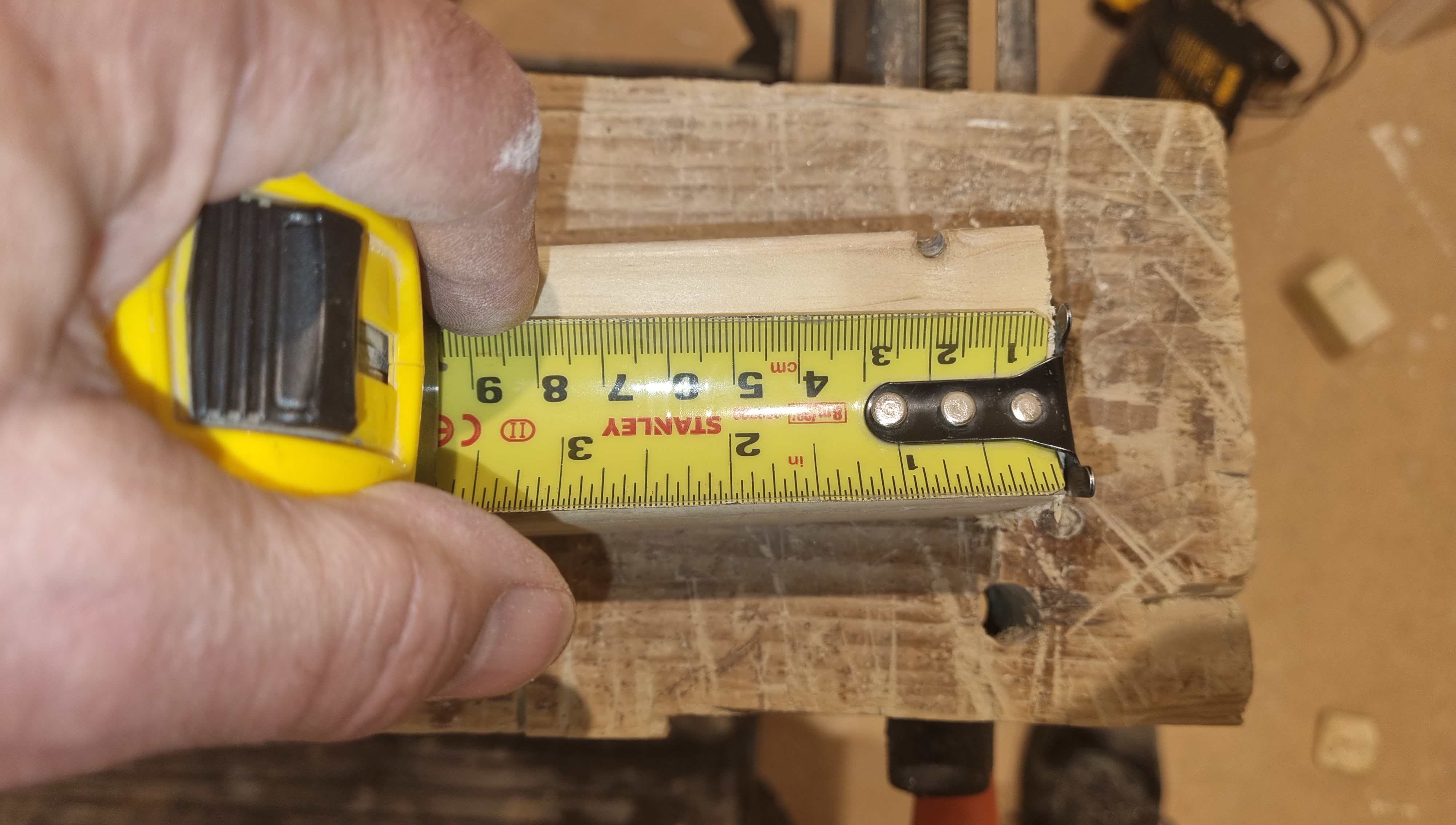
You see, to me that is a right handed tape measure, you hold it in your left so you can read the numbers the right way up and use a pencil (or whatever) to mark off your length with your RIGHT hand Worth thinking about 😉
-
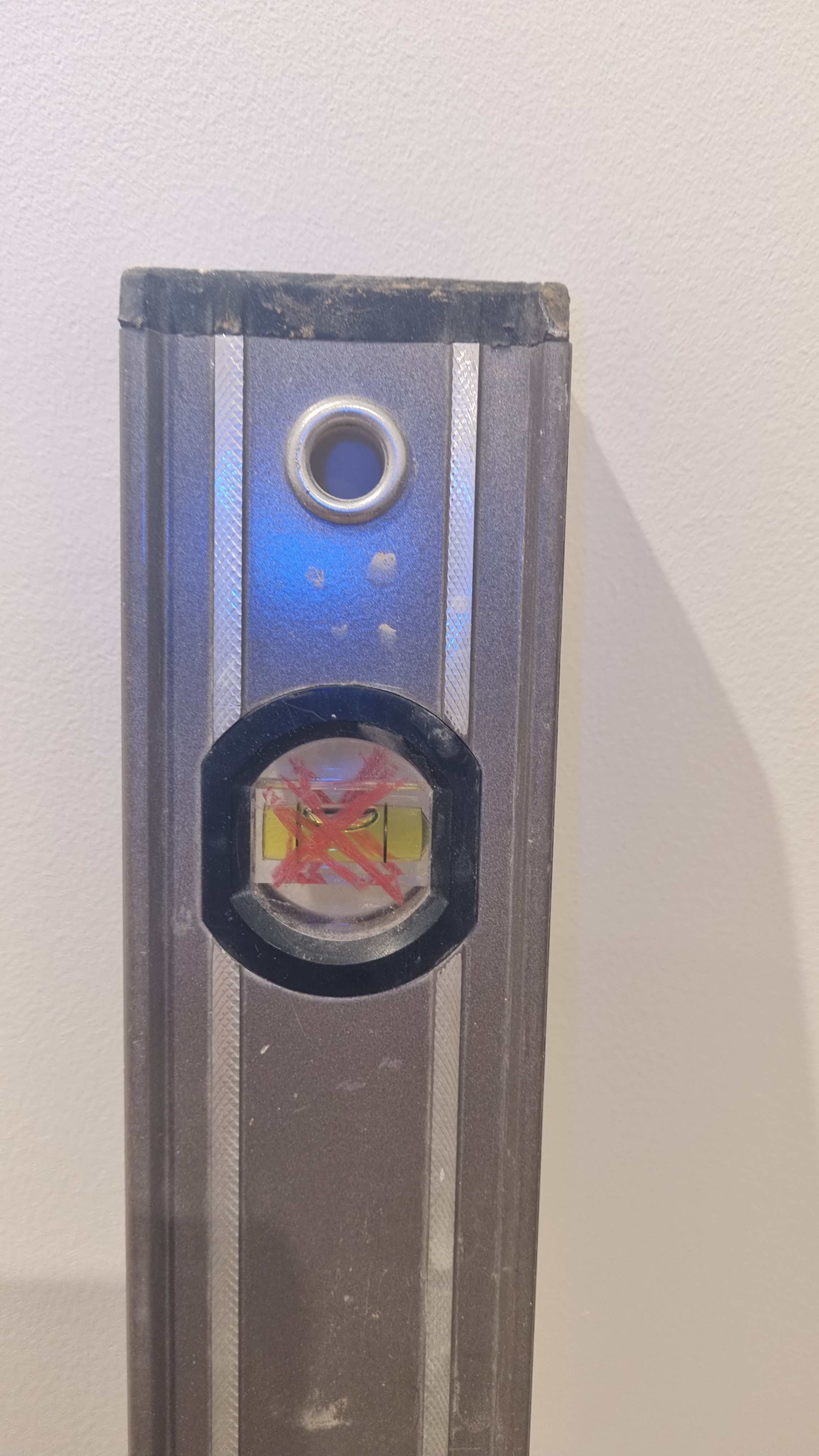
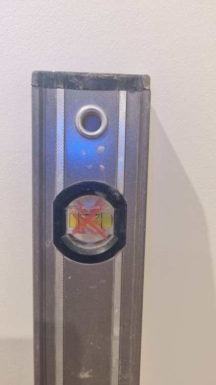
I've also got a spirit level that is incorrect on the vertical at one end. The house is called "Crooked Lodge". For clarity, I am mainly right handed but with a reasonable degree of (made up work incoming!) ambidextriosity.
-
Have I got a left handed tape measure, or am I supposed to mark with my left hand?

-
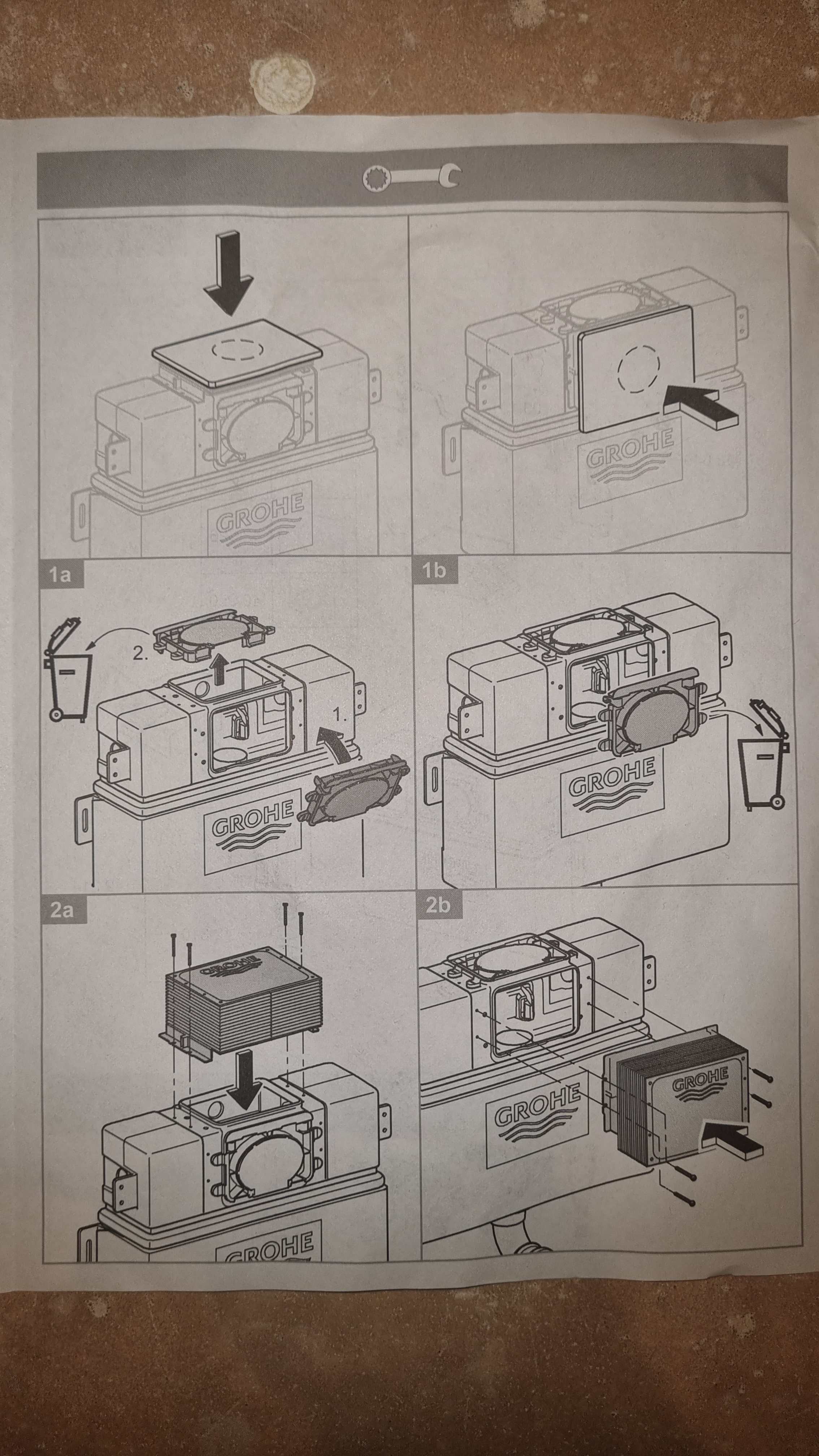
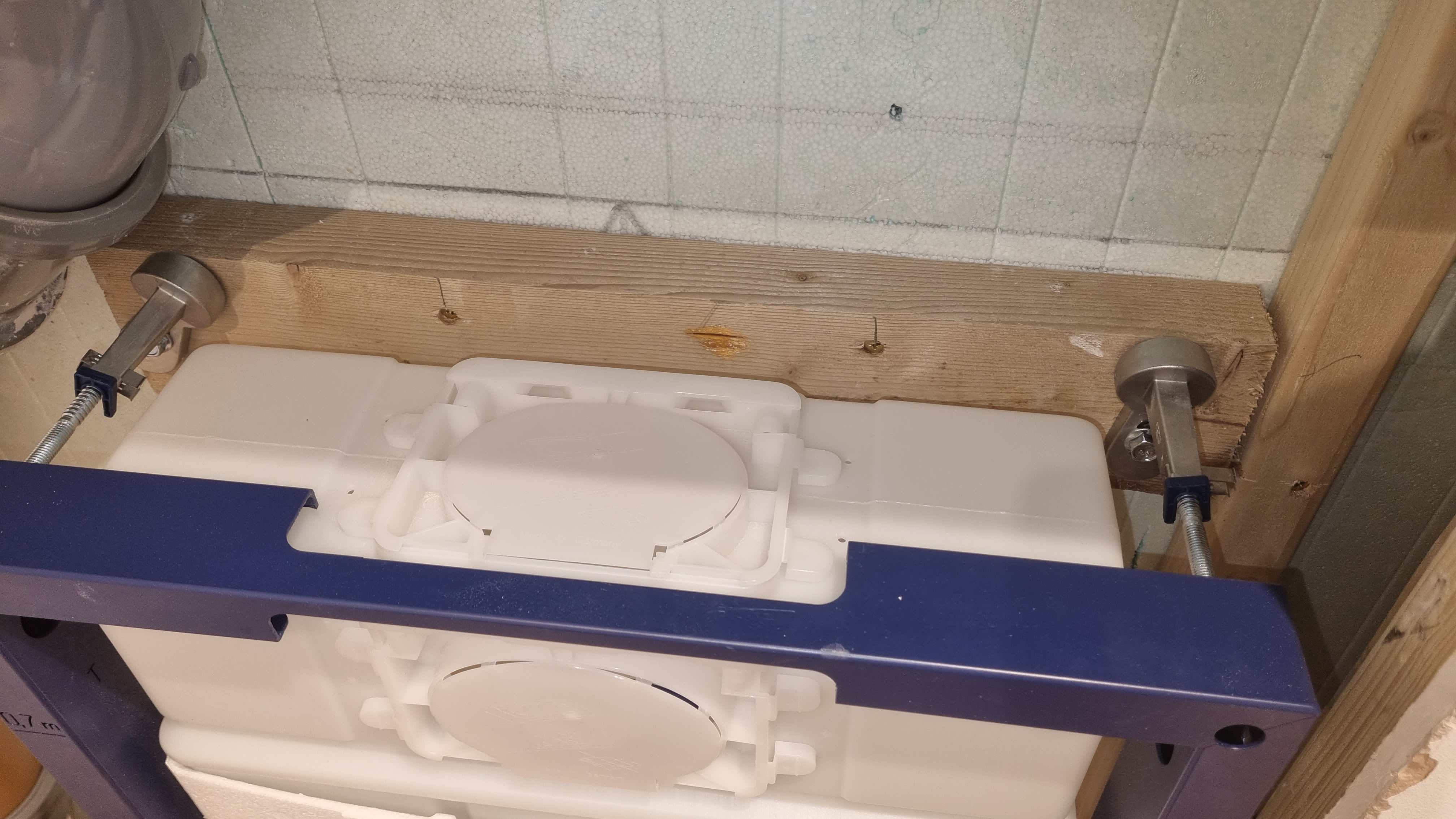
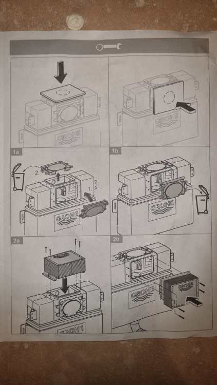
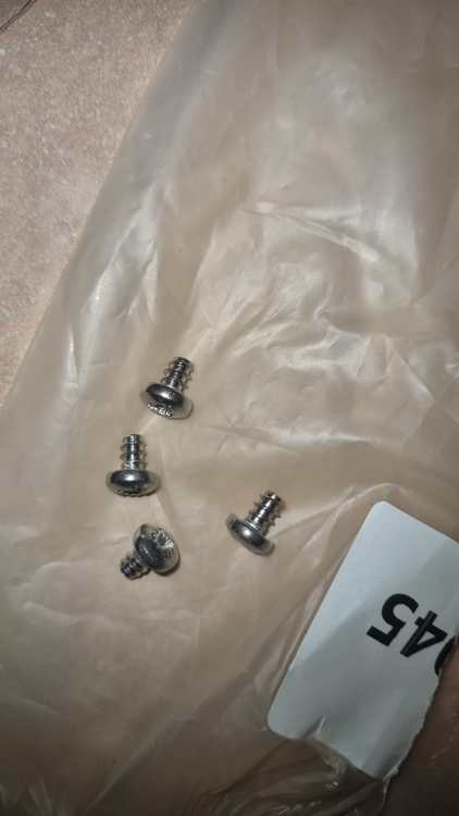
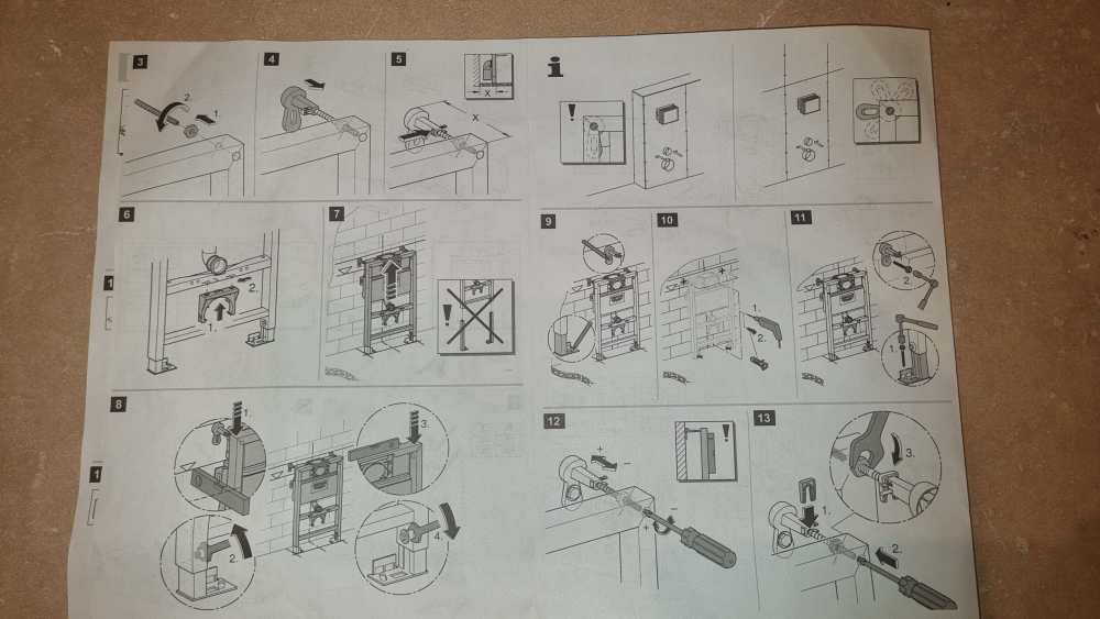
Next the cover, which for us is on the front, so the right hand side of this page to be followed. Note the actual size of the screws in comparison to those in bottom pictures And we're now here. Also still trying to figure out the 10 parts circled, that I figure are something to do with the two threaded rods that will ultimately hold the pan. There are other parts that came with the pan that I think replace these parts. A pause now, while I sort out replacing the plaster board that I had to remove to re-route the drain pipes (another thread exists about that)

-
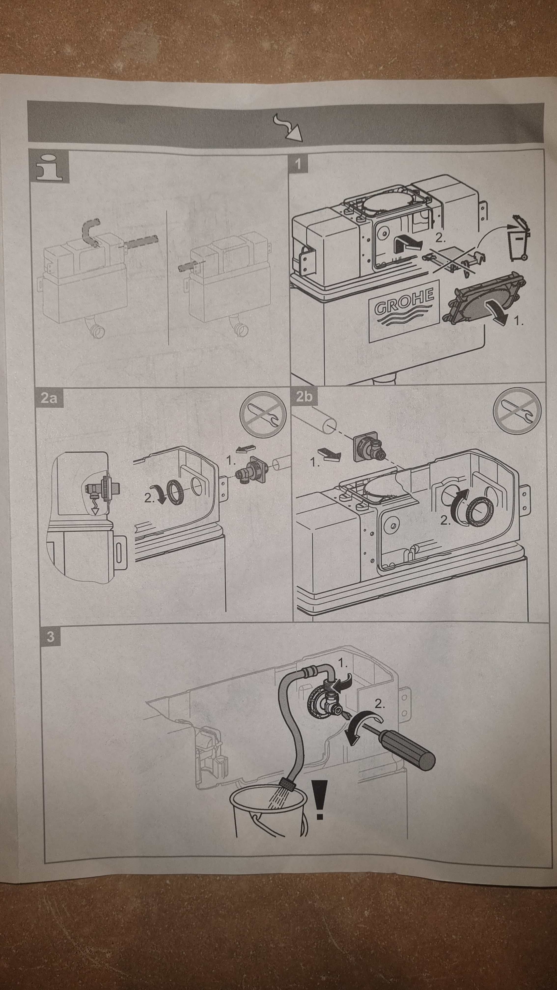
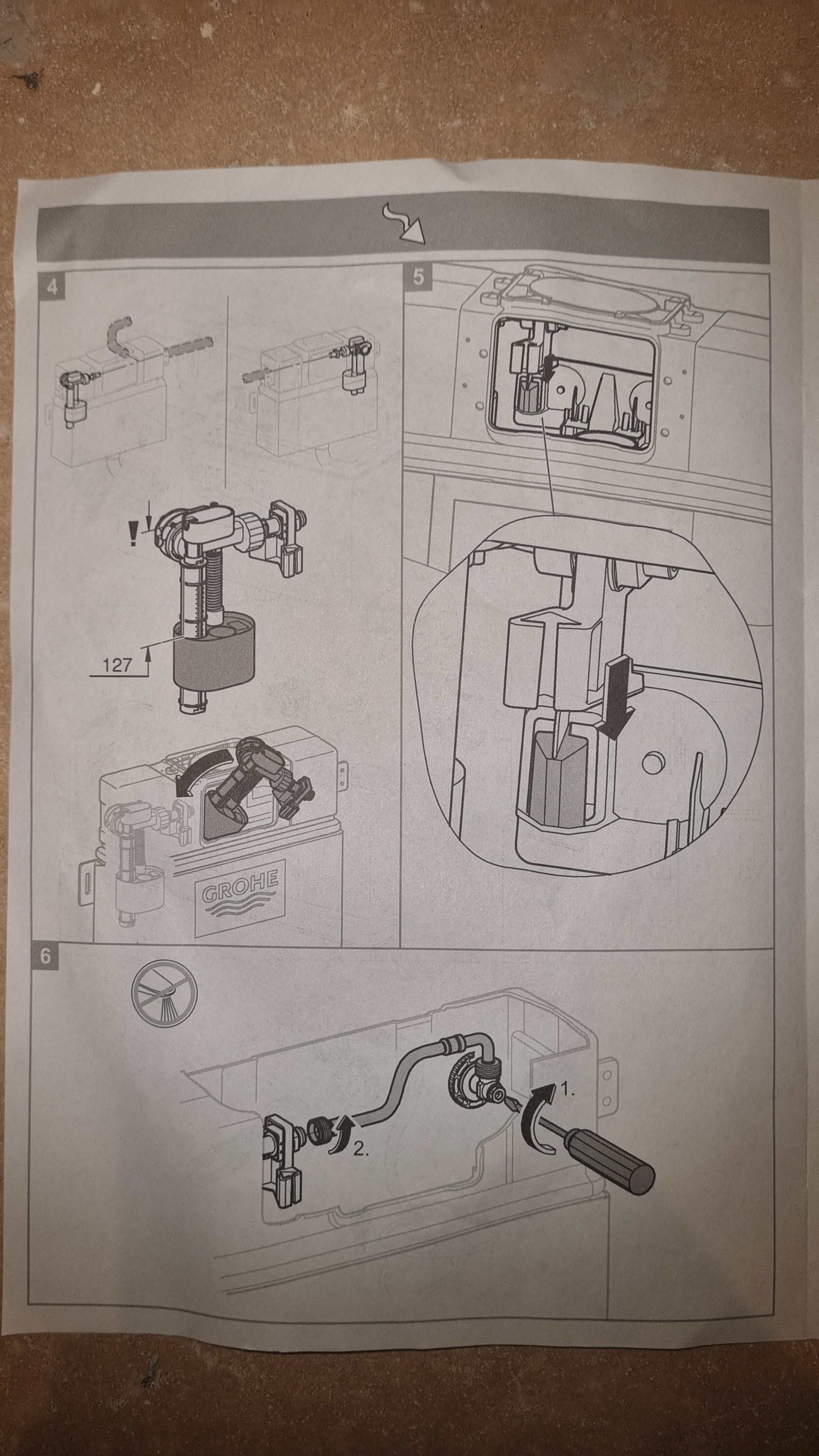
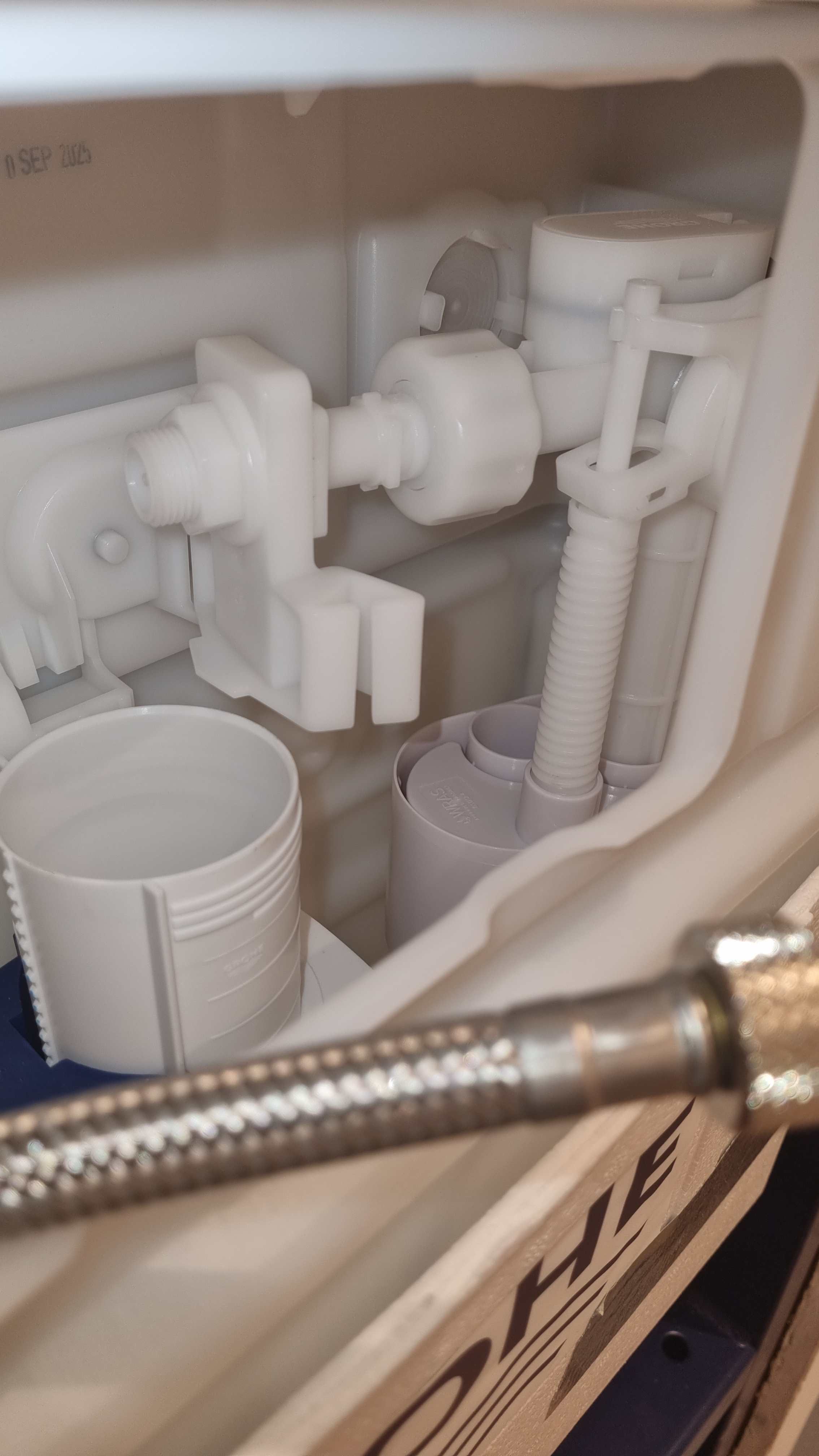
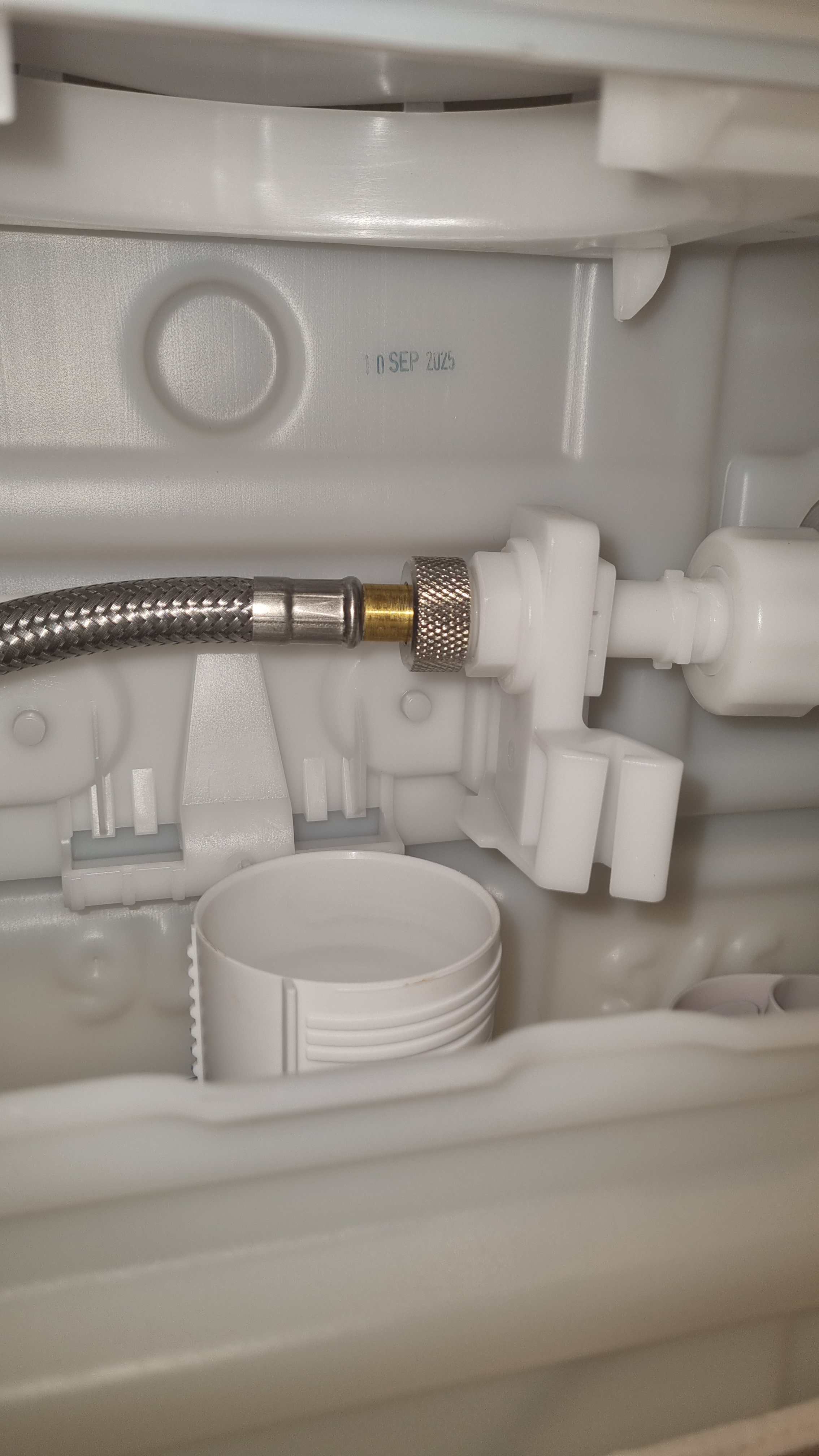
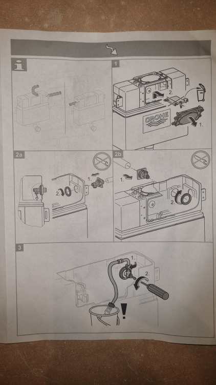
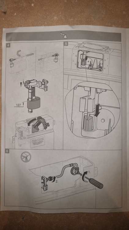
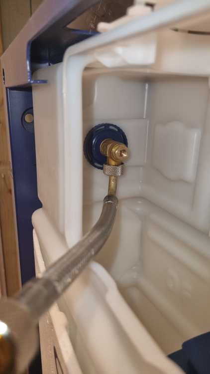
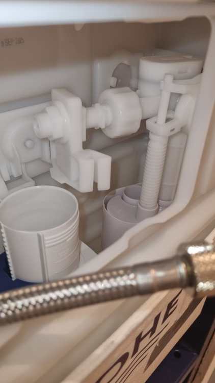
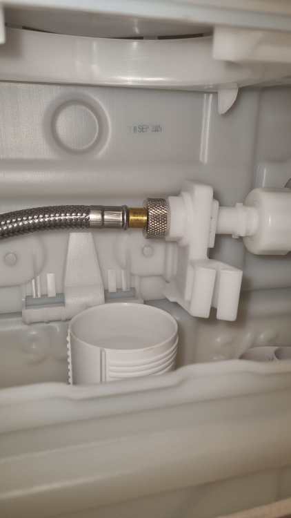
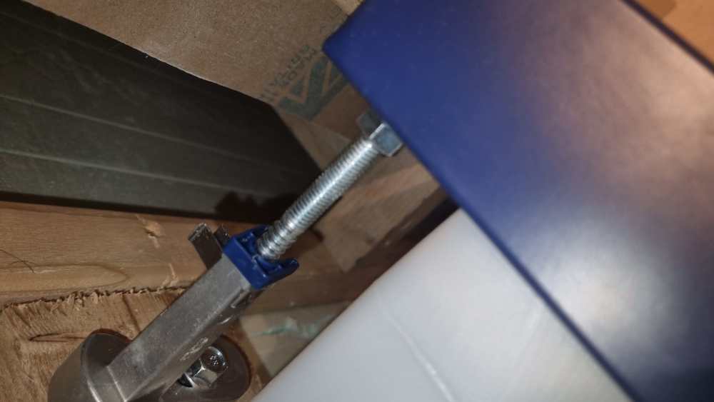
My above next steps are on hold. Moving to the water feed and flush mechanism. There are 3 option for where the water will come in - L or R side, or R rear. I'll be using L, not shown in the photo of instructions. This means the float mechanism fits to the right, again not shown in the instructions. For me, it looks like this:-
-
Ooh, must remove the horizontal battens already installed and introduce them to a power tool 🙂 Won't bother with the spacers. Waste of time and money IMHO.
-
There's a flush button?
-
What wall type should I use?
BotusBuild replied to BotusBuild's topic in General Self Build & DIY Discussion
Hi Susie (and David). It will mainly be used for stacking cars if I get to spend the VAT reclaim on what I want 😀 but it occasionally could be used for "servicing" and I thought a roll about stool in combination would be the way forward. Also, I'm looking at "sinking" the slab foundation to get 4- 500mm more headroom. Together I think these two approaches will work, but if they don't SWMBO has other ideas for the VAT reclaim 😀 -
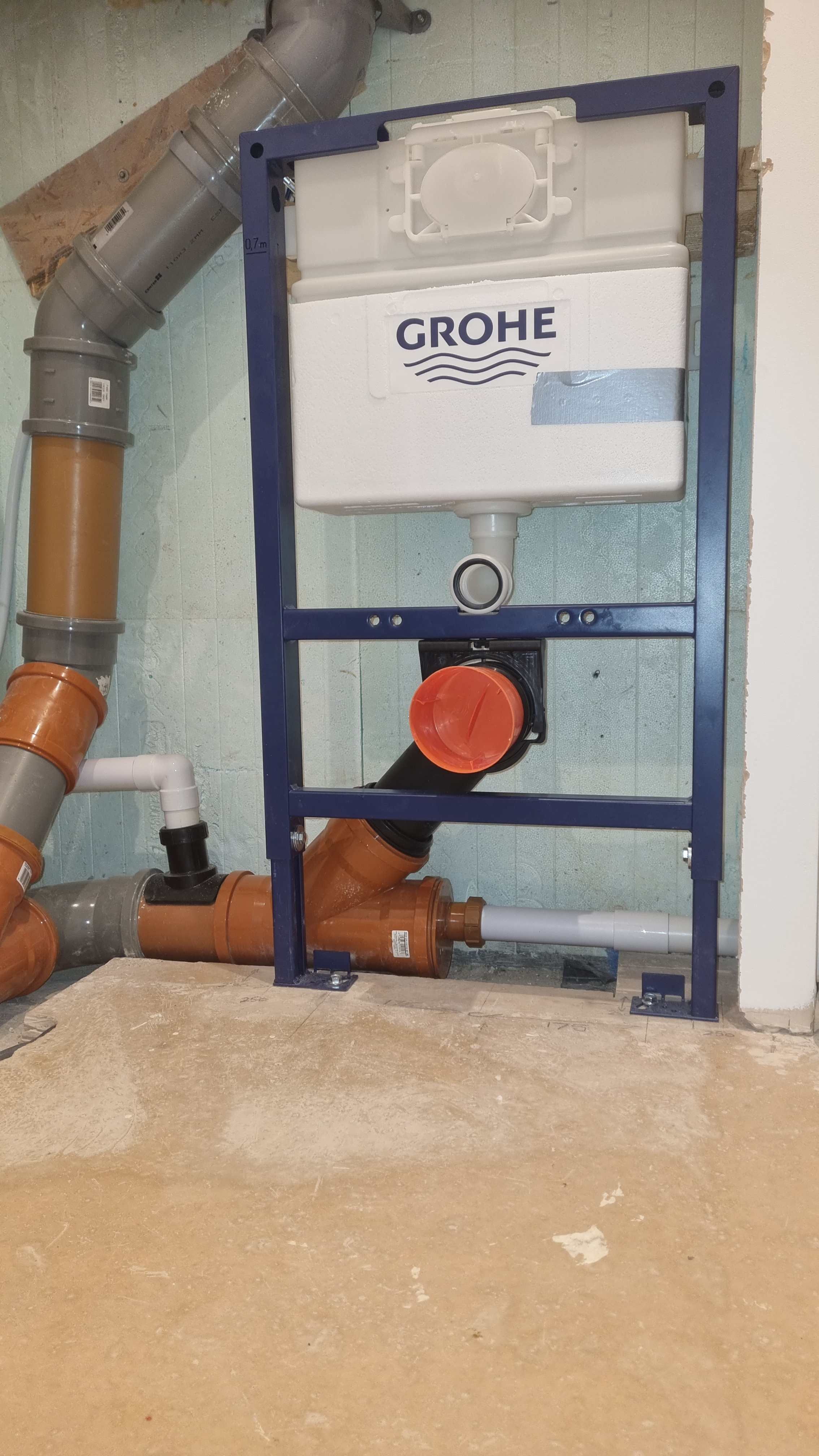
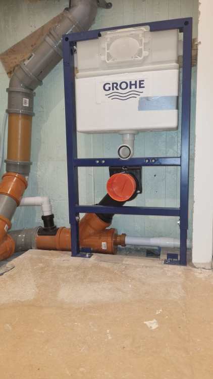
Here is the frame fitted Better explanation of the Grohe instructions HERE that I took to fit to this stage. That topic will be updated with the extra steps still required.
-
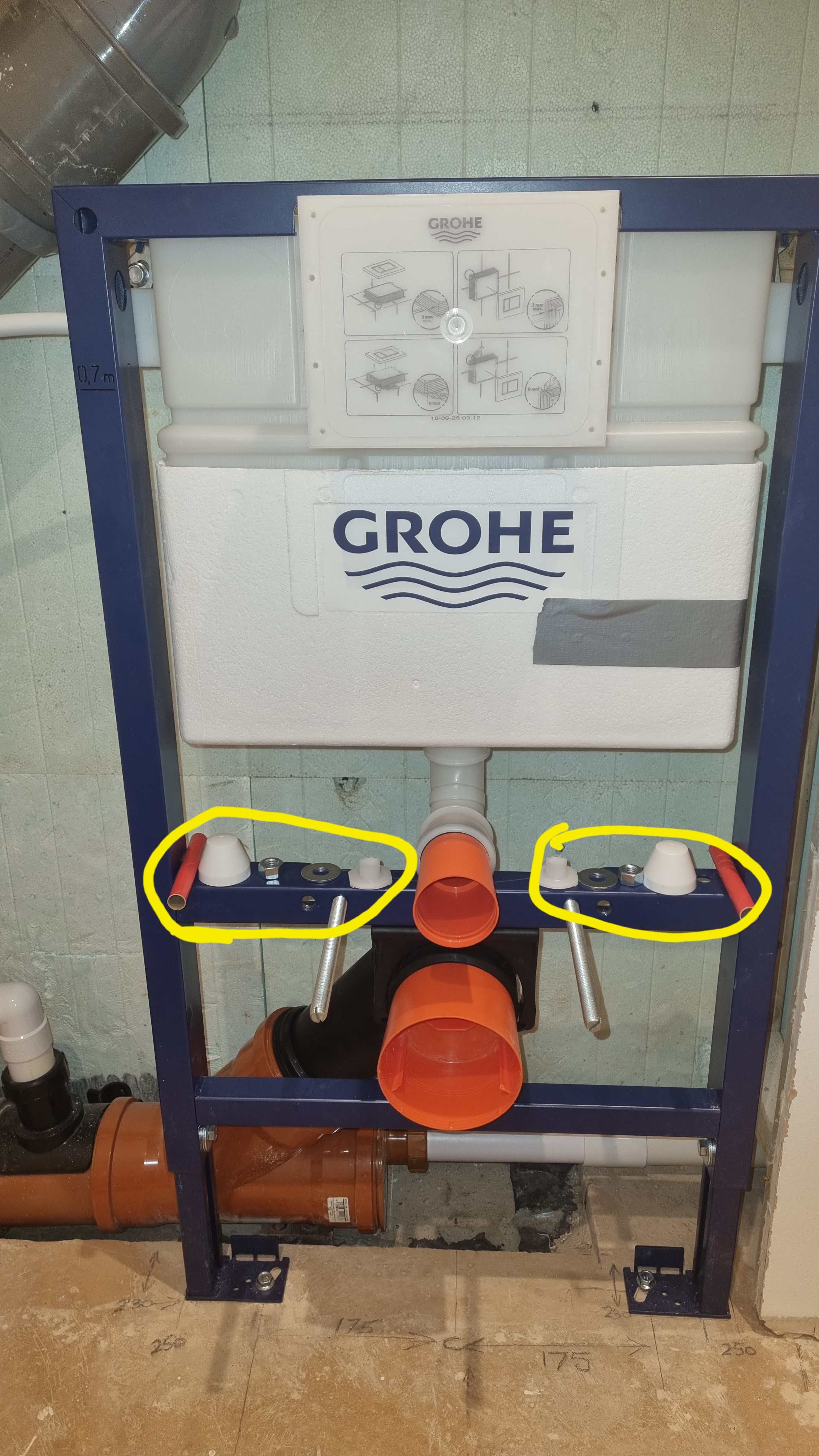
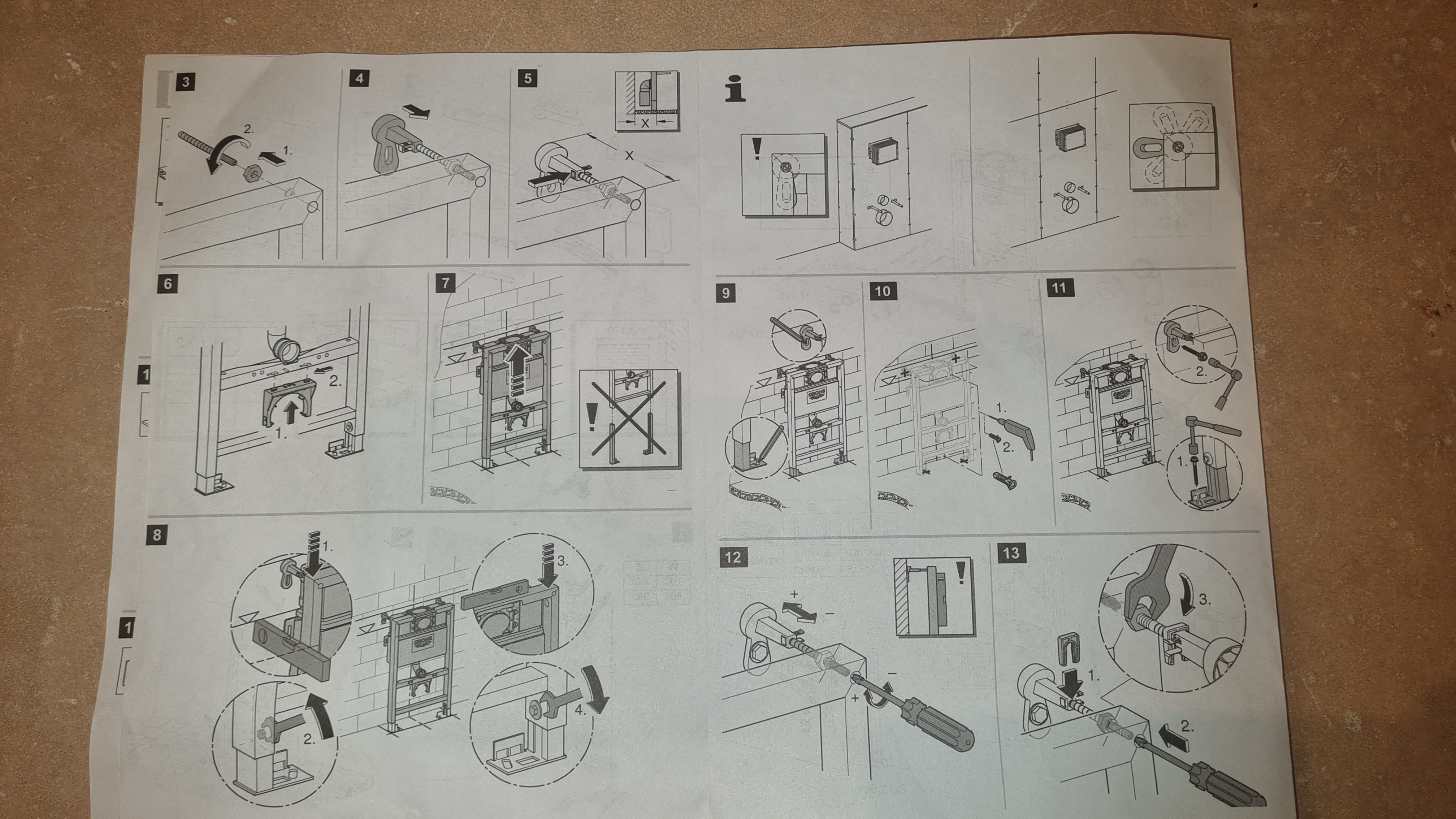
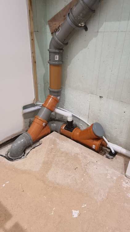
Following these steps I added that piece of wood to the wall Drilled the four holes, two on the floor, two in the wood (my "wall"), then fitted the frame And made the adjustments to these parts to level make it vertical and tightened the nuts and inserted the little plastic lugs Finally, attached the waste to the Y junction. Ready for these steps next

-
Not even if it a full flowing shower 😀 (statement, not question)
-
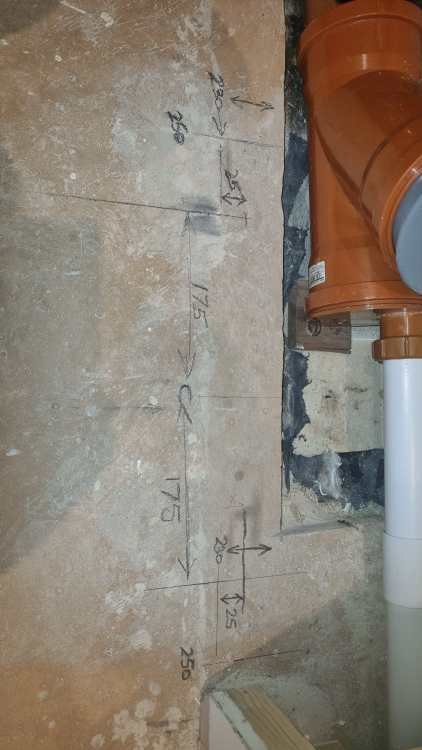
And more measuring. Time to pick up a power tool !! Are your sure those measurements are correct??
-
"Measure twice...." 😀
-
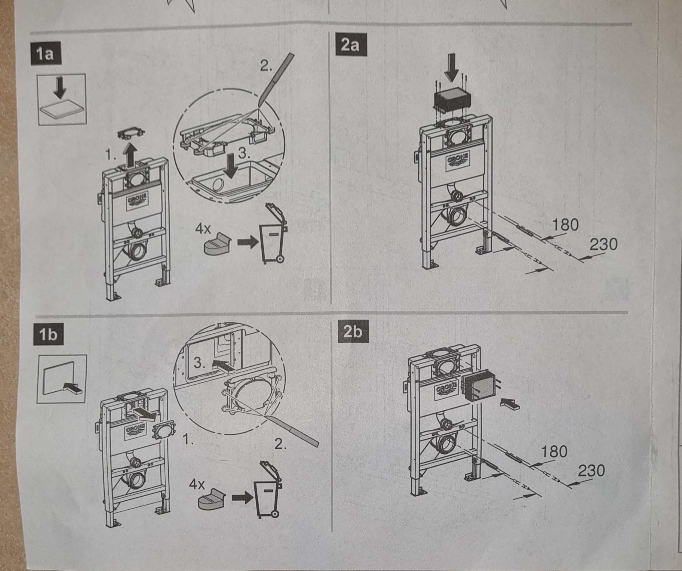
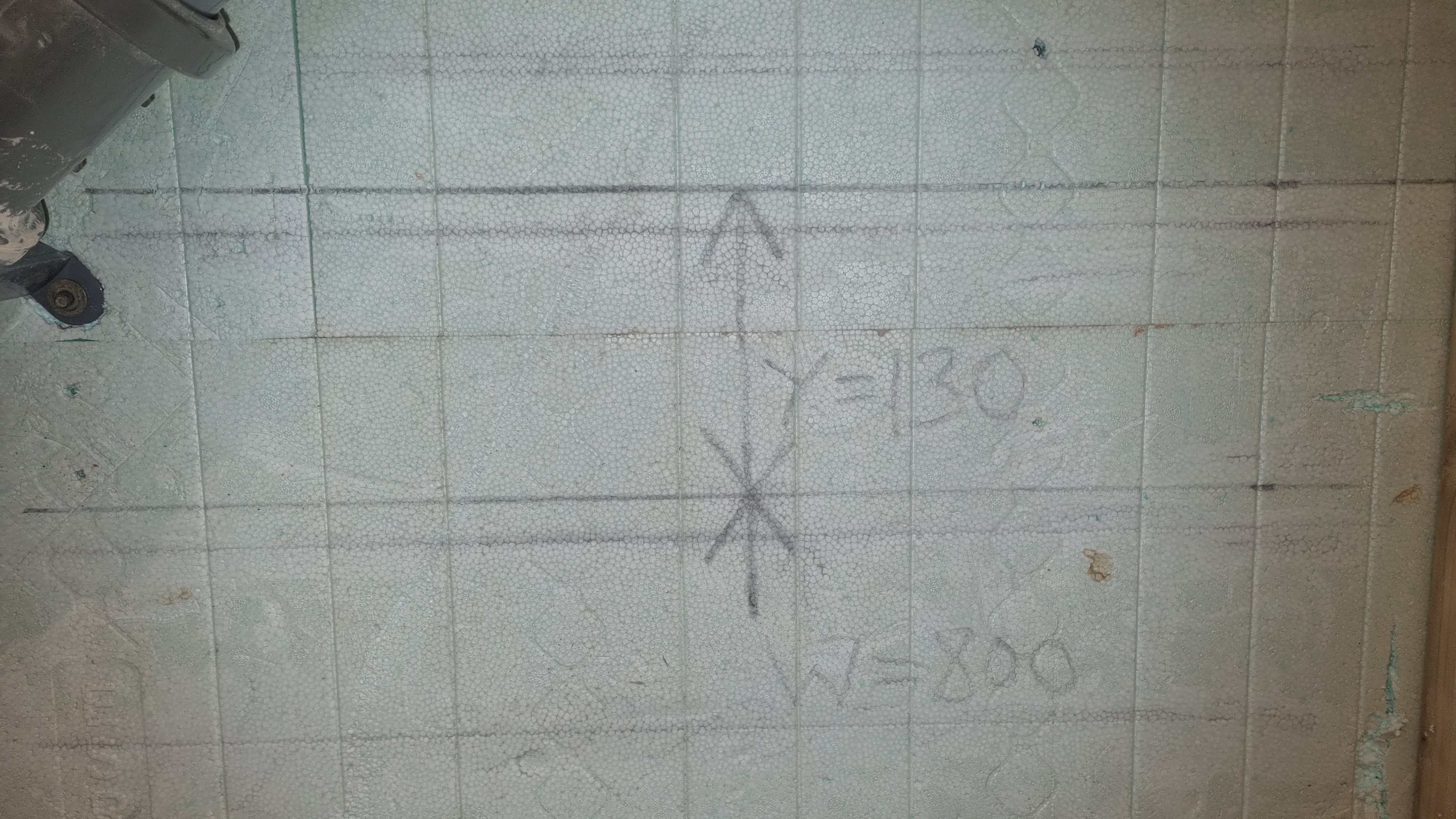
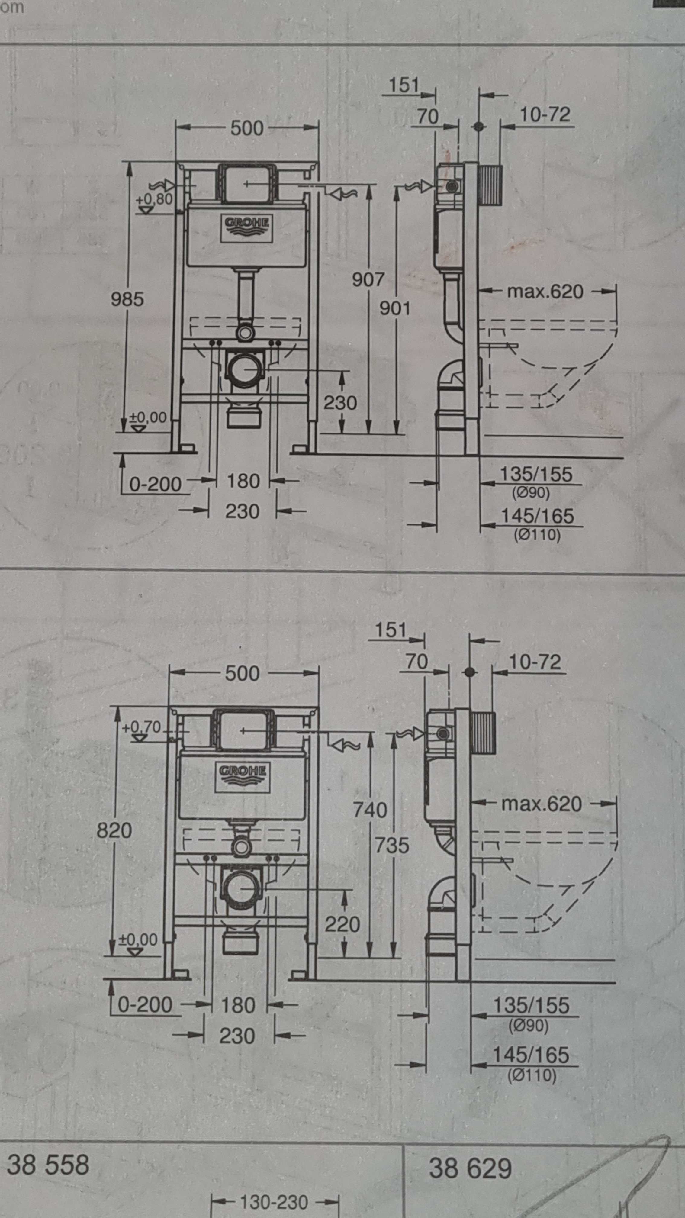
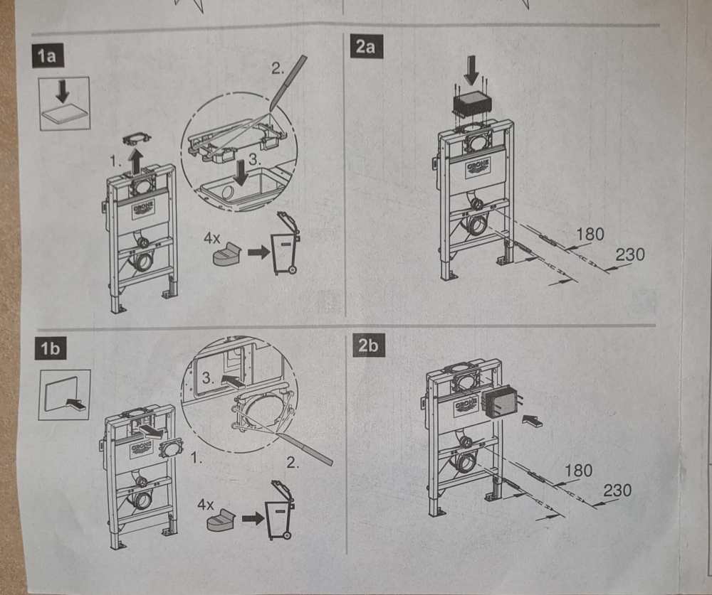
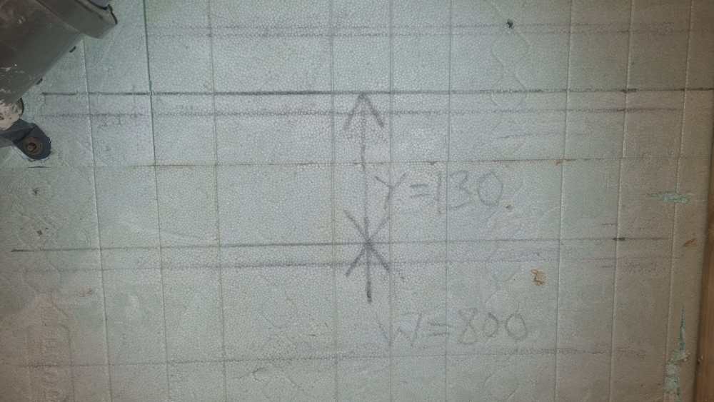
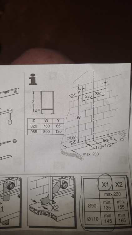
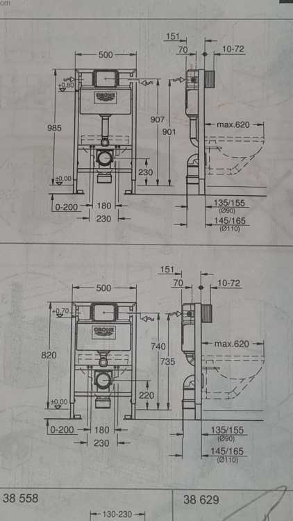
This one's a humdinger 😀 Takes the Z figure (985 in my case), then measure W (800 from the table in the picture) FROM FINISHED FLOOR LEVEL!! See that dashed line. Look where it goes. Finding the centre line of where your waste will be is easier if you're going vertical, a littl more difficult if you're going at 45 degrees 😀 The 175 figure is where you will be drilling holes for fixing the bottom of the frame, the 230 where the brackets for the top fastenings will be. Take the time to get all these marked out correctly. Remember the adage "Measure Twice ...." I ringed X1 below, but that's wrong as my waste will be T 45 degrees so I'll be using X2, so a min of 165 and a max of 230 from the wall.
-
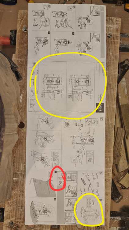
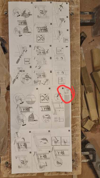
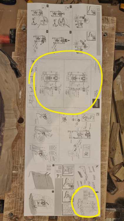
Next pay attention to the following two little pictures ringed in red, as they signal the start of instructions for whether you attaching it direct to a wall, or into a frame. I'm attaching it to a piece of wooden joist which is screwed into an ICF wall. (Pictures later)
-
I've started a topic HERE to cover GROHE frame install for others to reference.
-
I'm going to document the frame install to help some others in the future, as I have found the lack of words of explanation on the instructions to be a hurdle. By way of example, this, I think is the first bit you need to consider, and it hinges around the height of the waste pipe, 220 or 230mm Combined with this, where Z comes from the above picture And thise two picture come from this If I didn't know better I'd say these instructions were designed not by a German! In my case, I think my Z is 985mm as the waste need to be at 230mm. Here goes ...

-
Done. Frame time
-
She knows where I am (HINT)
-
What wall type should I use?
BotusBuild replied to BotusBuild's topic in General Self Build & DIY Discussion
Already happened 😀 -
I was thinking 2 x 45's, but then how to get that waste in is the issue, which I haven't figured out a solution yet apart from cut and glue (NO!)