
MikeSharp01
-
Posts
5644 -
Joined
-
Last visited
-
Days Won
16
Everything posted by MikeSharp01
-
 Its controlled by the heat pump and its the valve that came with the heat pump - this one I think: The ZVM28
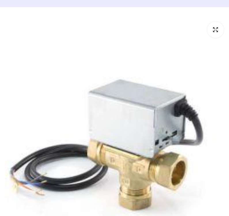
-
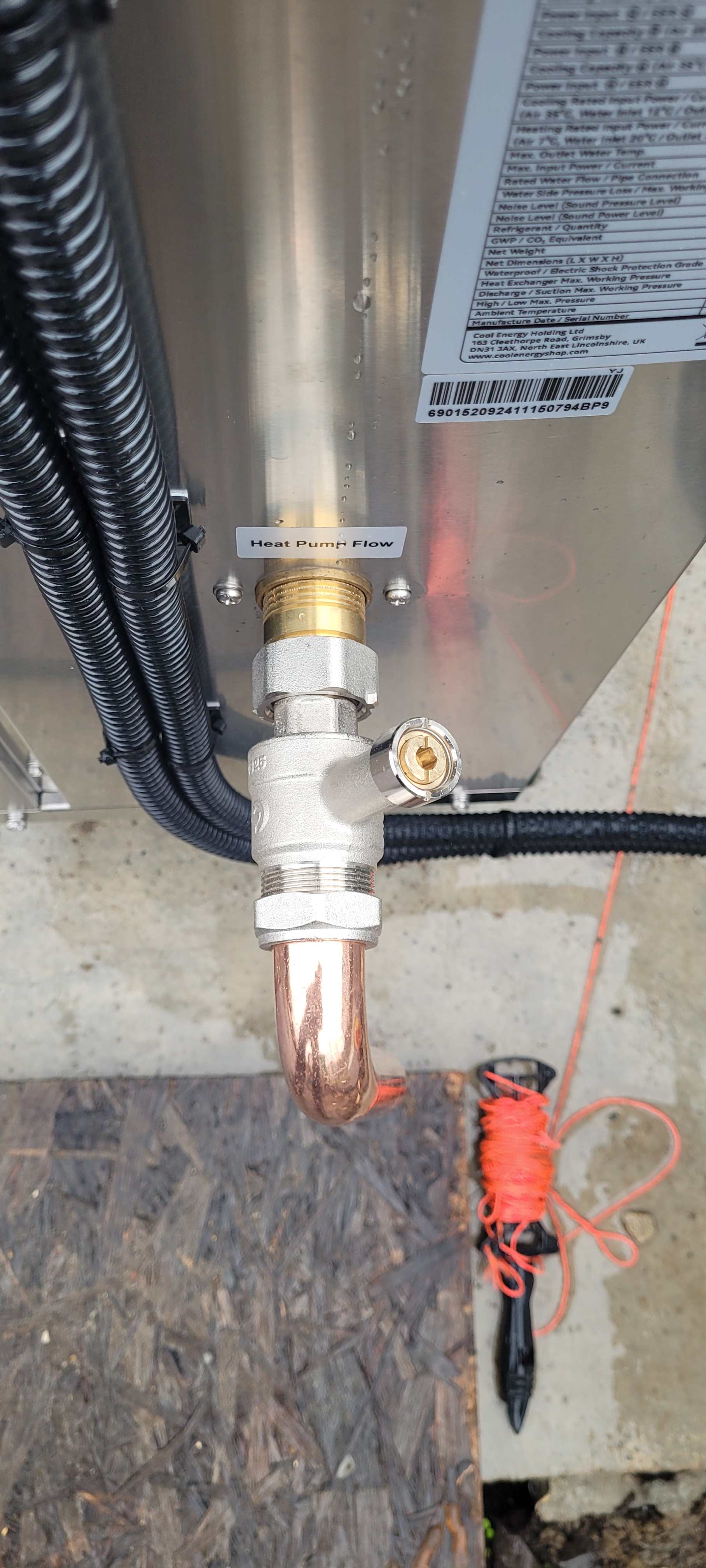
Been running the new heat pump today testing and commissioning the EMON heat meter. The heat meter is working well and telling me I get about 4.2 COP on heating the slab - with a cold slab at about 12oC. When I switch to heating the hot water the changeover happens smoothly and the heat meter starts reporting HW correctly BUT when I switch back at the end of the valve close we get an awful thump, I guess water hammer? Is this common and what might the / a cure be?

-
No we decided to get a new one, well two new ones, which I fitted yesterday. Yuk job.
-
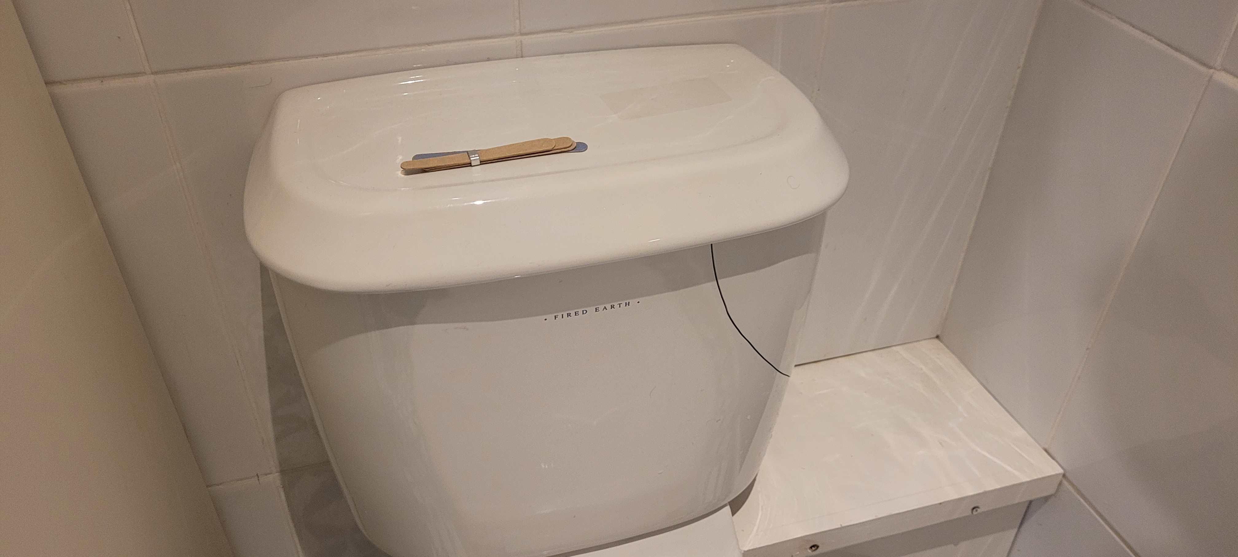
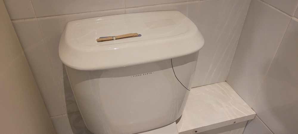
Yes sorry name mix up. To much happening in my world. After 20 years of trouble free service a cistern in one of our bathrooms just cracked without provocation, not been used since Christmas, drowned the router in the stairwell below, left us with no Internet and water everywhere. Sadly its a Fired Earth unit so no guarantee possible- still as I say it has done 20 years.
-
It is, at least that's what I asked for, it doesn't have a fuse anyway.
-
We don't need the immersion to clear the legionnaires risk the heat pump does that. So for now I have wired it straight to the CU breaker via a switch fused unit. So as of now we don't have automation of the immersion but there appears to be nothing preventing me using my contactor approach. The rules are clear that you can put stuff in between those fixed points provided it meets the wiring regs etc which is how the diverters do it. So I won't have any high current stuff on / around the tank other than the connection from Switch Fused Isolator to the immersion heater. Final job is to commission the heat meter & EmonPi. Hopefully Sunday, then I will have some real data to play around with and get an impression for how good or bad the system is.
-
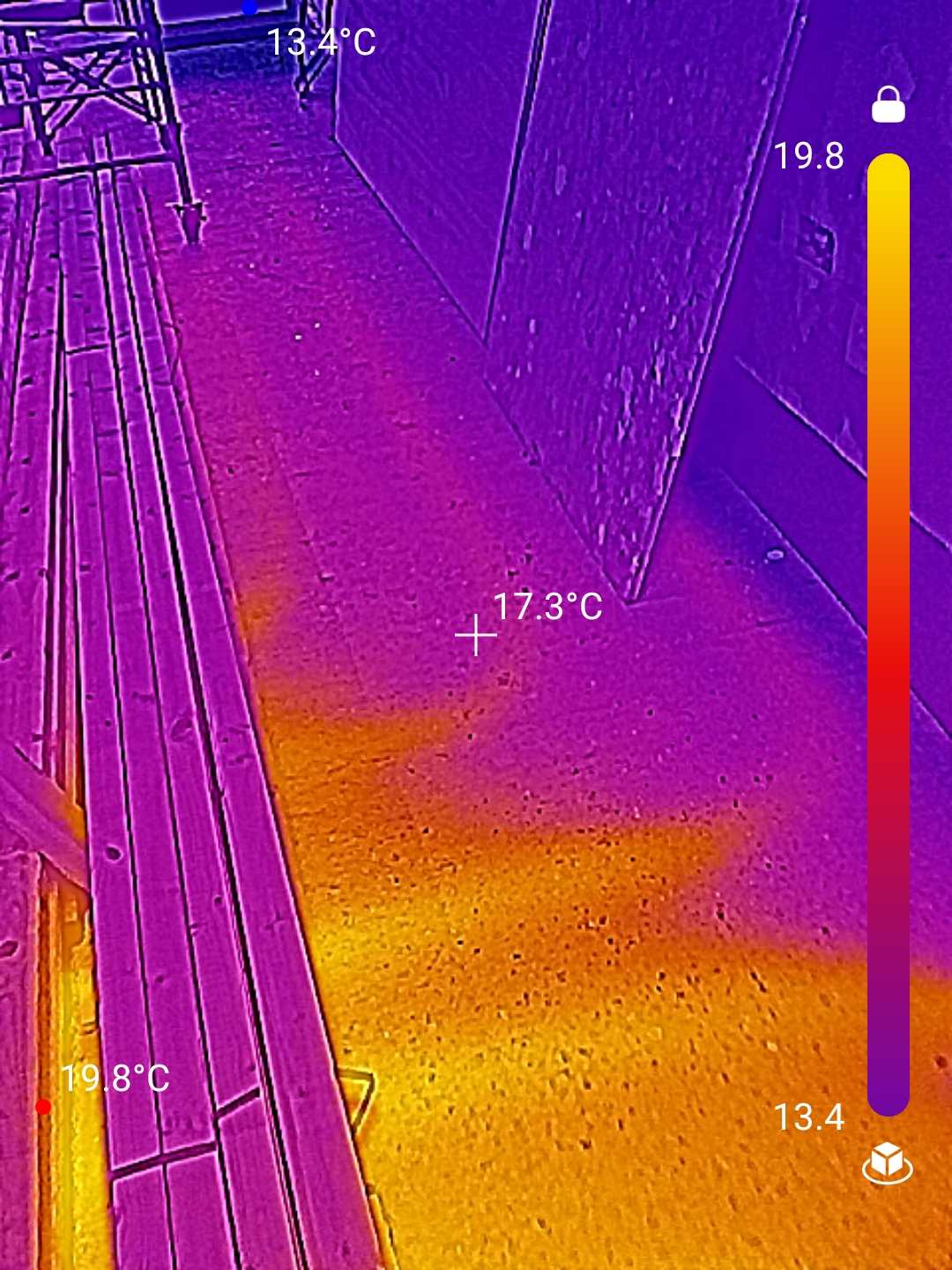
Well, it's gone very well. On Wednesday the system was commissioned with no issues so the MCS cert and the G cert will be issued. When I get a bit of time I will write up the whole thing for a blog as its been a very interesting mission but we got there. It was great to see the heat coursing through the slab pipes. I have not calibrated the Camera for emissivity.

-
outer hebrides it seemed like a good idea at the time…
MikeSharp01 replied to Chris HB's topic in Introduce Yourself
Self building is a mission (pardon the pun) but an absorbing and rewarding one, we are looking on in awe! You blog is wonderful - keep it up and keep on keeping on.- 56 replies
-
- 2
-

-
- western isles
- isle of lewis
- (and 2 more)
-
Makes sense, not sure we will ever need it here in the deep south!
-
Nothing in the manual about that, manual is sparse to say the least, but it does have an output called 'additional heating'. As I mentioned above the heat pump can make water at 75oC, so it shouldn't need additional heating.
-
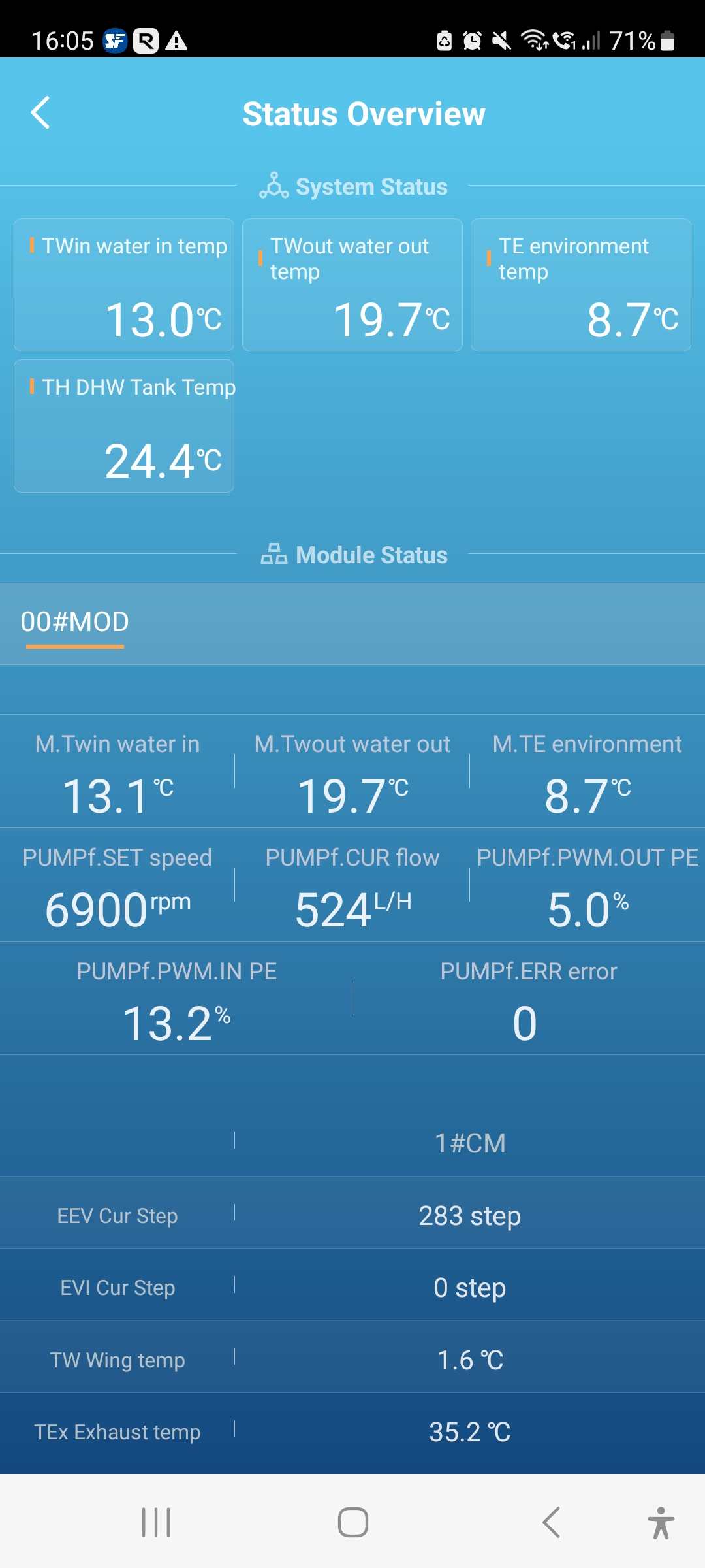
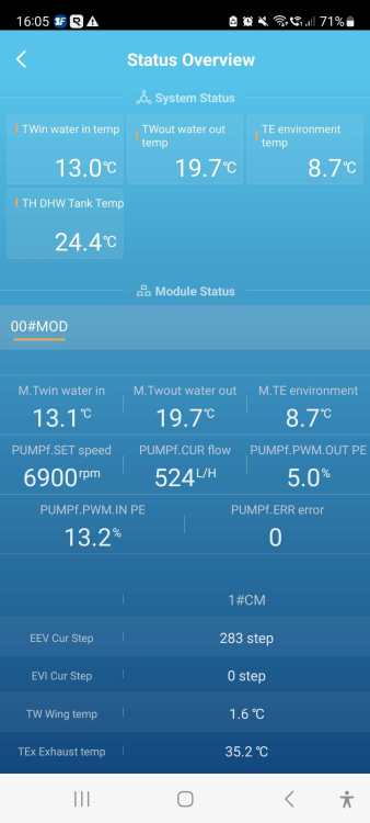
I am sorry, I was not trying to complicate things, I think maybe I was confused by the dual stat being part of the kit, so I thought we'll as I don't have all the other gubbins in the Telford schematic, on the assumption the dual stat was some sort of safety device for the immersion and knowing that the heatpump cannot make water above 75 degrees that I should just provide a fail safe for the immersion using the dual stat via a contactor and because 24V controls are in my blood I took that approach as it both protects the tank and allows me to turn the immersion on or off remotely. Nick is also right everyday needs to be a school day for me and nothing about this stuff is difficult - just new to me, so having you chaps around to point out the straight and narrow is a real help. Anyway the good news is I have just powered up the heat pump for the first time and it is now working on heating the slab also tried domestic hot water and that works but the changeover seems to cause a differential pressure error (174 on the cool energy app) Anyway here is the current status 20 minutes into heating the slab.
-
None of the heat pump functions are controlled by the 24V system only the immersion and the heat pump does not want to control that as far as I can see. I chose to put the dual stat into to the 24V side because the switches in the dual stat look flimsy, you cannot get a piece of flex capable of carrying the full current of the immersion into the gland provided in the dual stat box and I didn't really want high current switching on the tank. If it will help I can wire the dual stat into the immersion direct I just need to be creative with the gland problem.
-
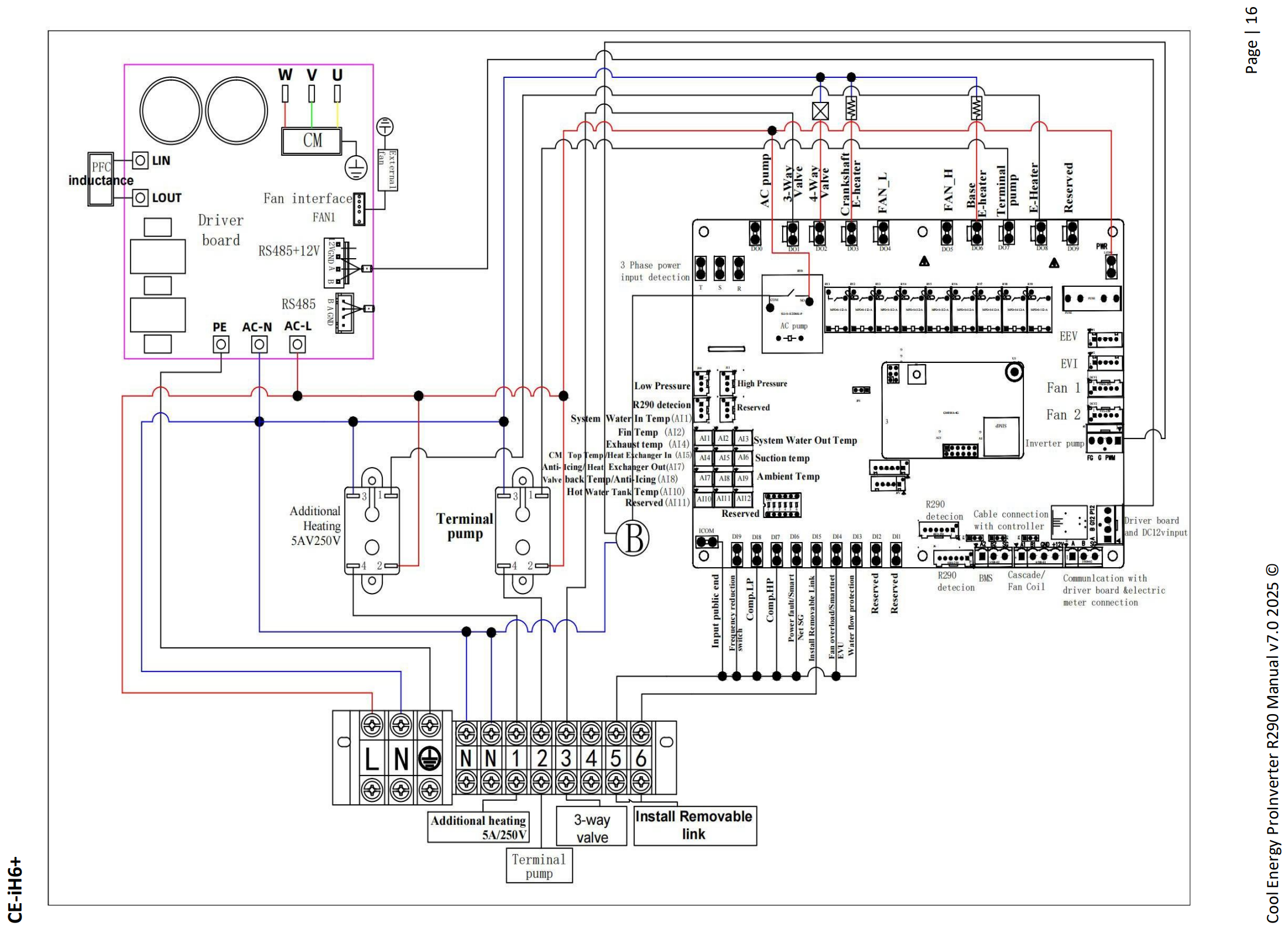
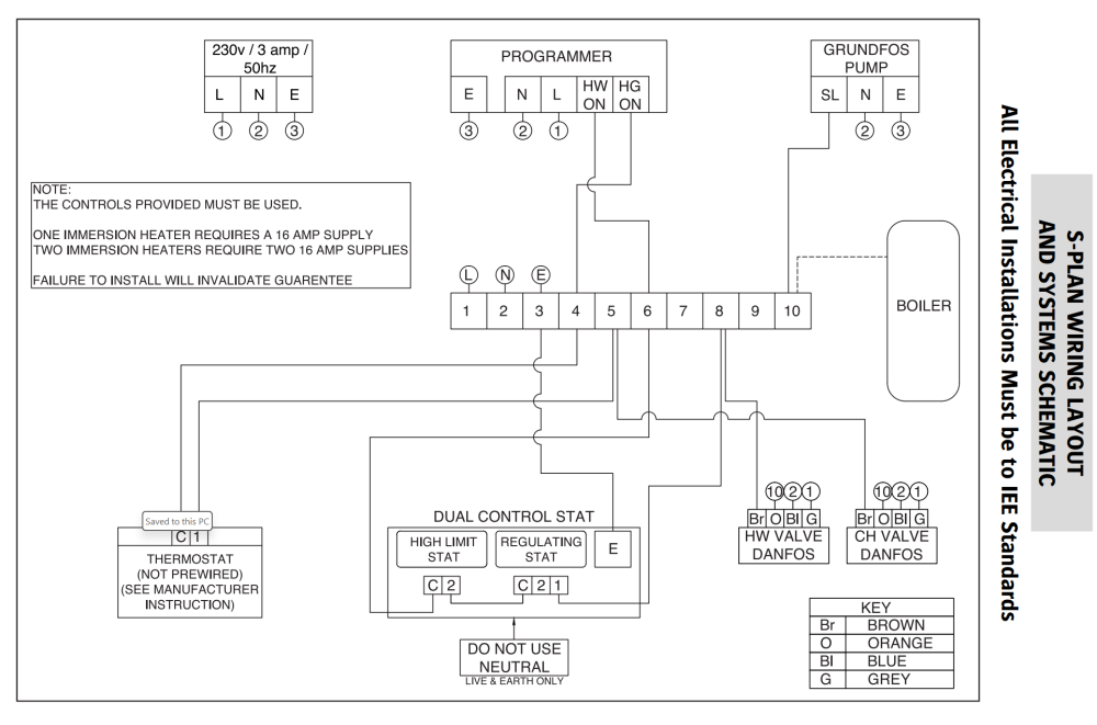
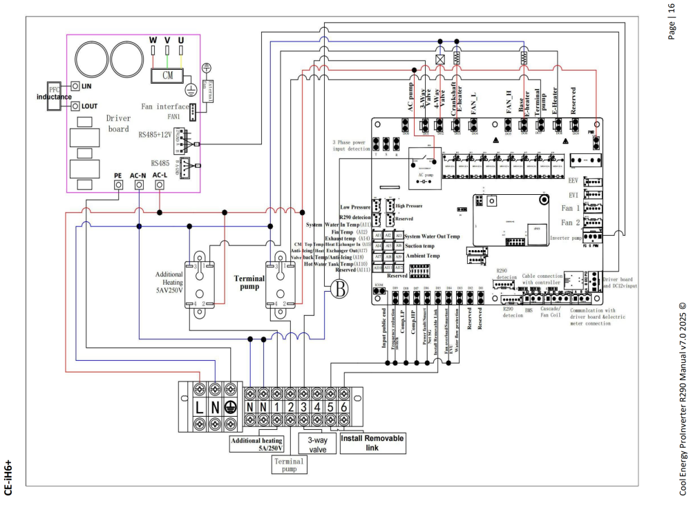
Which schematic are you referring to. The only one I have is in the manual and looks to refer, as you say to a boiler based system. (Link: https://www.telford-group.com/download.php?file=VG9ybiBUZW1wIEluc3RhbGwgR3VpZGUgMjAyMy0yNDUucGRm) It does say controls provided must be used but I obviously cannot use the above circuits as I don't have; the programmer - that's in the heat pump, the three way valve operation - that's controlled by the heat pump, the pump - that's in the heat pump so I just used the dual stat to limit the immersion. The max output temperature of the heat pump is 75oC so it should not need any boosting as legionella should be gone with 30 minutes at 60oC. I cannot see anything in the manual for the heat pump about an inbuilt booster heater but it does have provision for what is called additional heating (5A@240V) as an external connection. (See image below) So I am using the dual stat to control the immersion (despite it being an intelligent one - which can do all kinds of things on its own. I could take the additional heating signal from the heat pump (terminal 1) and use that to drive, via an appropriate interface, the call for immersion signal discussed in the thread above but as far as I can see the heat pump manual makes no reference to the use of that signal other than as part of the commissioning check list and nothing to say this additional heat source should be controlled by the additional heating signal.
-
Yes I have, via the contactor route I discussed. I am not sure if the Heat Pump has a boost heater I will check that but whatever happens I don't want that heat getting round the UFH so control of three way valve won't happen but I could just kill the power to HP I suppose using the same signal.
-
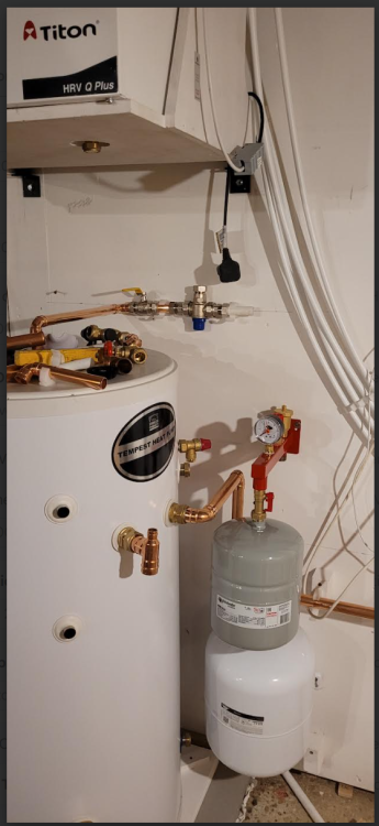
Yes the safety stat but as it's a heat pump it cannot reach dangerous temperatures so I have assumed that I don't need it for that, is that not OK, and have put it into the immersion circuit as described here: and you commented on at the time. It's a Telford Tempest Heat Pump cylinder and the two pockets are shown in the image below, which was taken as we worked out the pipe runs, hope it is enough but I can get a full picture tomorrow - not quite sure why I don't have one already. There is nothing low down only the two showing.
-
Almost complete on the HP install all flushed through, pressure tested everywhere and filled for testing (still need the inhibitor) Powerup tomorrow, would have been yesterday but weather stopped us because you have to take the lid off the HP to make the final electrical connections if you want a BMS connection. Anyway the final challenge is to fit the temperature probes into one or both of the pockets in the UVC. There are two pockets one at about 50% height and one at 75% height and there are two probes. One (A) looks after the immersion heater and the other (B) looks after the Heat Pump - sends Domestic Hot Water (DHW) data direct to the HP presumably for the HP to know it has got the water to the required set point. The tank is quite dumpy and 200l so I assume it makes no difference as the tank probably does not stratify so well that it matters. Have I go that right? To help me out I have used the top pocket for both so if it does stratify I am working on the hottest water and I can read the temperature from the BMS and its reading the same temp as the immersion limits.
-
Should I be concerned about this crack?
MikeSharp01 replied to Whats the crack's topic in Brick & Block
An old Architect of my acquaintance once told me that if you cannot get your hand into the crack then you do not need to worry about it, hopefully one of our friendly Structural Engineers will be along shortly with a view. -
Just another thought, we kept the service void in the utility room and had we not done so we would have had problems with mounting things like threaded inserts through the VCL used for things like munsen clips and the like.
-
If you use a wood screw it punctures the membrane and fills the hole with the shaft so provided the thing it is attaching is down tight there won't be any leaks. So we didn't bother with anything other than screwing down tight generally, we got a 0.2 on the PH scale for our air tightness and there must be 1000s of screw holes through the VCL all clamping down wood, but only wood. As @saveasteading points out anything else will need special treatment. I tended to mount them with self sealing screws, such as the ones used to screw down roof sheets, or mounted them on a strip / square of mastic tape to fill any holes. Your worry here is jacking as your screw might push the two layers apart slightly but in the end the screw will fill the hole makes won't it. You have to plug the holes! We did cover every staple with a tape square and fastidiously marked damage for repair if we made any.
-
Thanks @SimonD I will get some loctite 55 - try and copy the pro's eh.
-
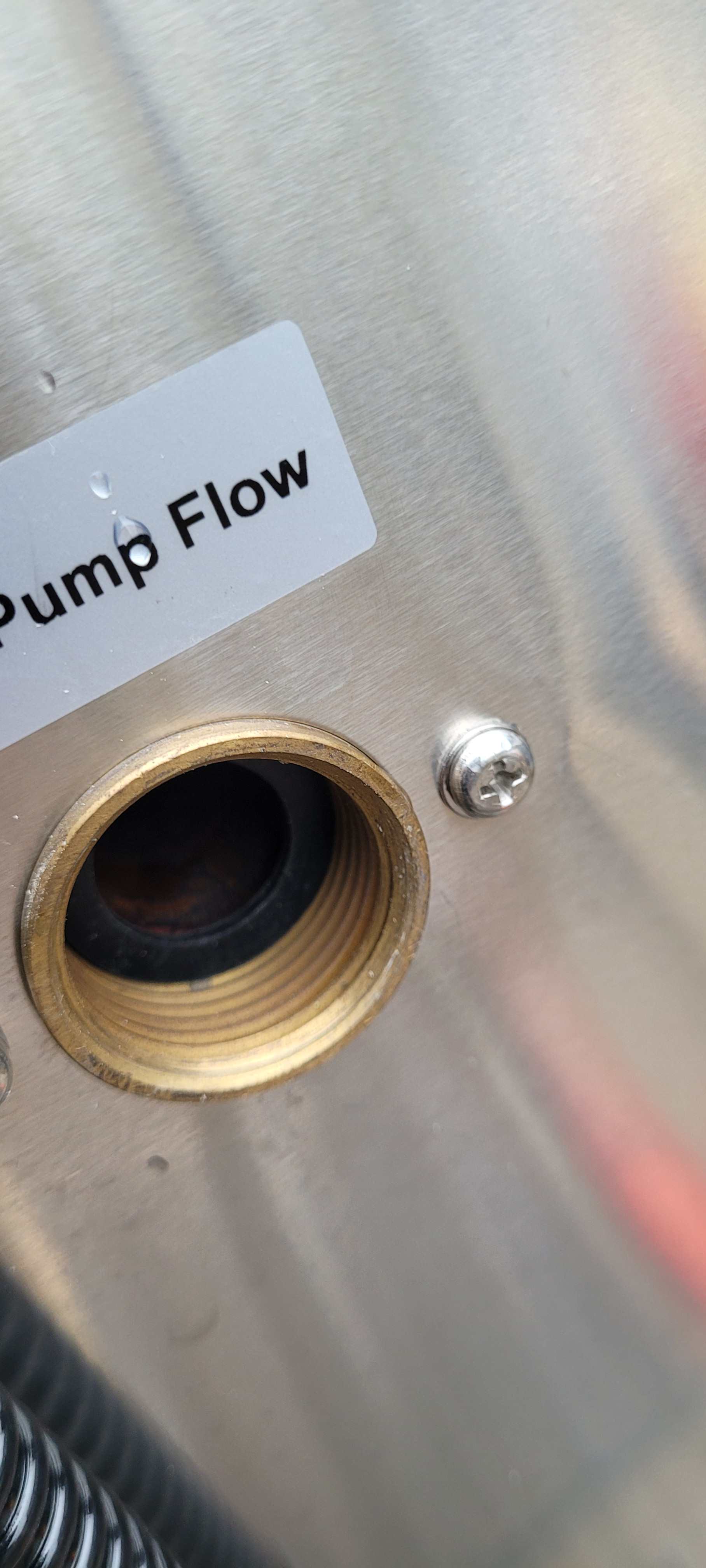
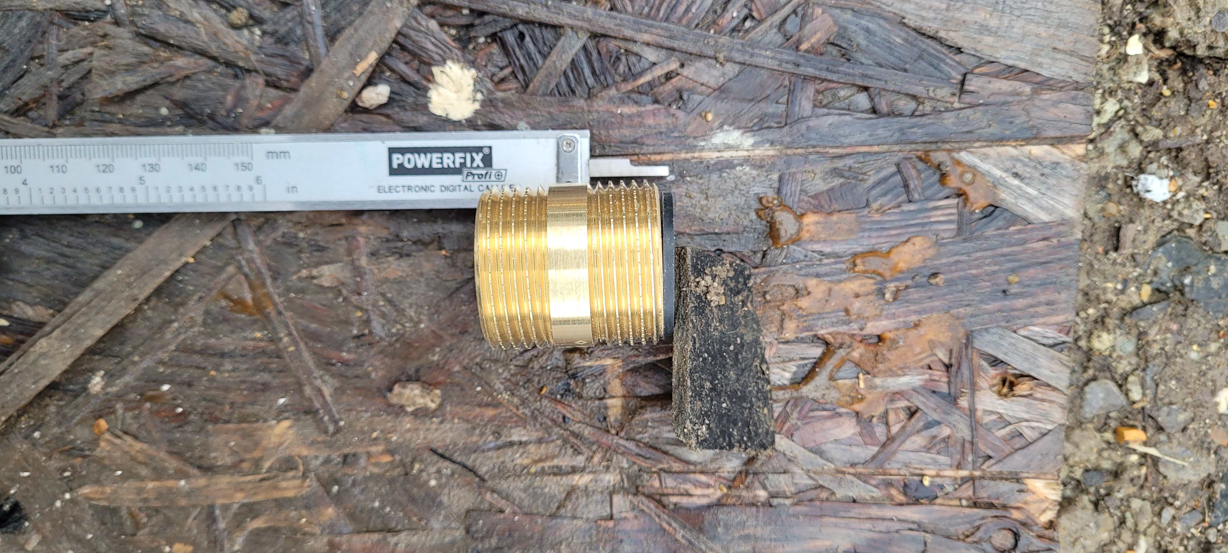
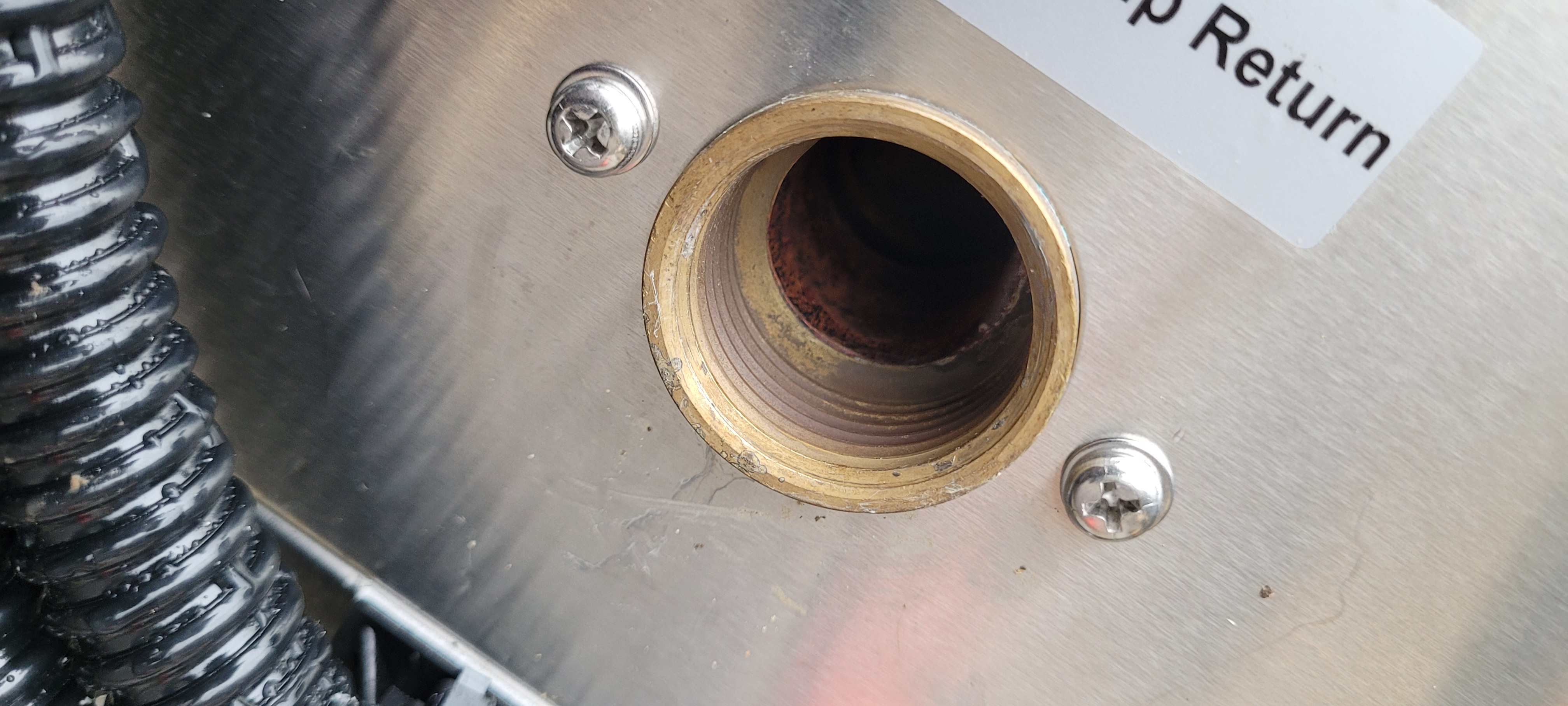
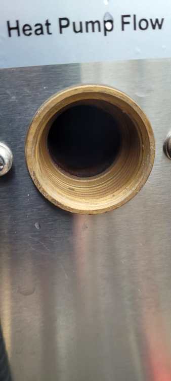
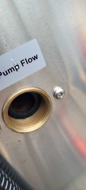
Yep here are a few. The total depth of the thread in the socket to the lip is 16.87mm the thread length of the barrel plus the washer is 15.76. Also on the return there is no lip more a radius to the pipe diameter inside.


-
Just tried it and the washer is floating when the barrel is tight and it does not look like it has a flat face at the bottom of the socket just a small lip!
-
That makes sense going onto the fkt face valve o it's the same for the female set into the machine is it - neat.
-
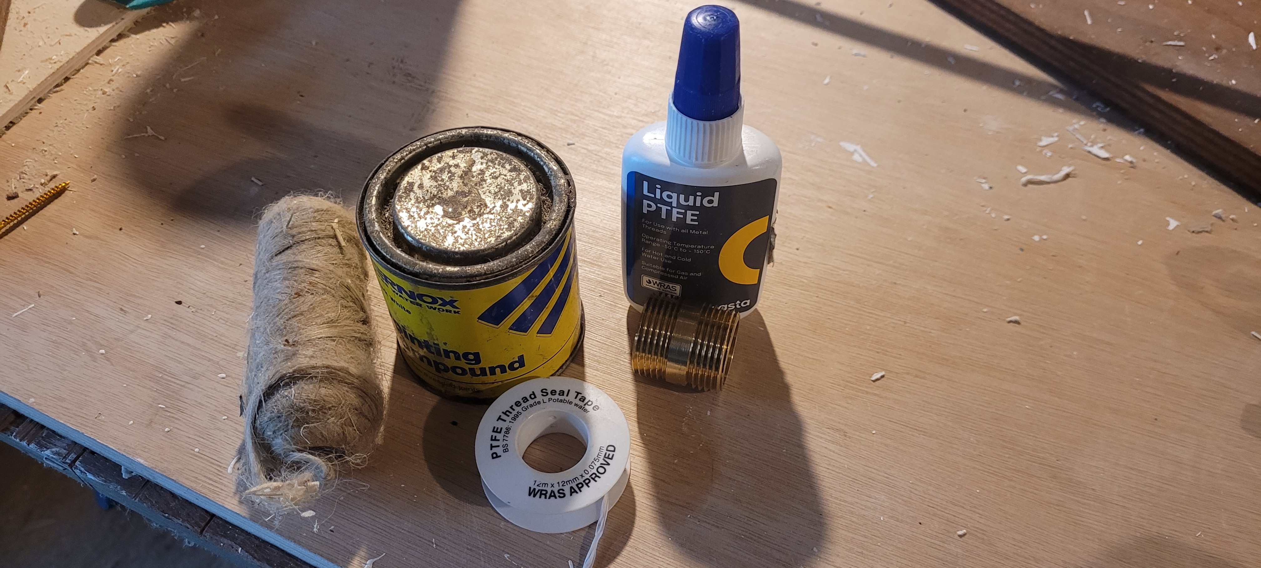
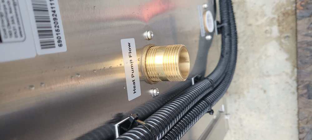
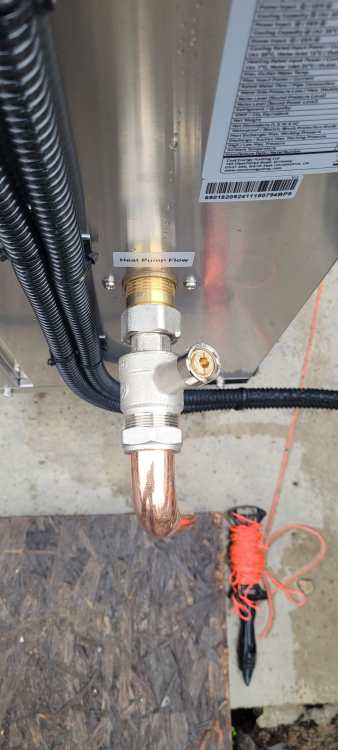
I am about to make the final water connections to the heat pump (HP). I want to use a 28mm barrel to the HP connecting to a flat face valve them a swept 28mm bend then onto the flexi to the flow / return pipes running alongside the HP. I was wondering what method to use the joint the barrel into the HP. Liquid PTFE, straight PTFE tape or a more old school method. I prefer the liquid PTFE but am happy to take advice from experts.

-
Which model is that?