
MikeSharp01
-
Posts
5644 -
Joined
-
Last visited
-
Days Won
16
Everything posted by MikeSharp01
-
 We are subject to the vagaries of Thames Water here and we have woeful water pressure and flow. We live on a hill that has a number of springs and is know for its wells hence I am thinking of installing a bore hole. So what are the issues and the likely cost? Anybody got any experiences of doing this?
 -
Don't the modern single block mcb+rcbo units do this, if not why do they have a neutral terminal.
-
Nope but I am going to - in the near future. So I can perhaps share the journey. Let's hope we can get advice. In our case we don't yet have the slates on so that I am hopeful that will simplify things.
-
What sort of construction is this?
MikeSharp01 replied to MikeSharp01's topic in General Construction Issues
Yes it looks like pilling blinding as there is a pilling rig there today so good spot @Mr Punter. So they drill core drill through the blinding and then put the piles in all very neat and tidy - no mud other than what comes out of the hole! -
What sort of construction is this?
MikeSharp01 replied to MikeSharp01's topic in General Construction Issues
Surface was flat clay - no rebar. -
What sort of construction is this?
MikeSharp01 replied to MikeSharp01's topic in General Construction Issues
the crosses might indicate that although they seem quite far apart for piles don't they? It will be interesting to see what happens next - I will report back. -
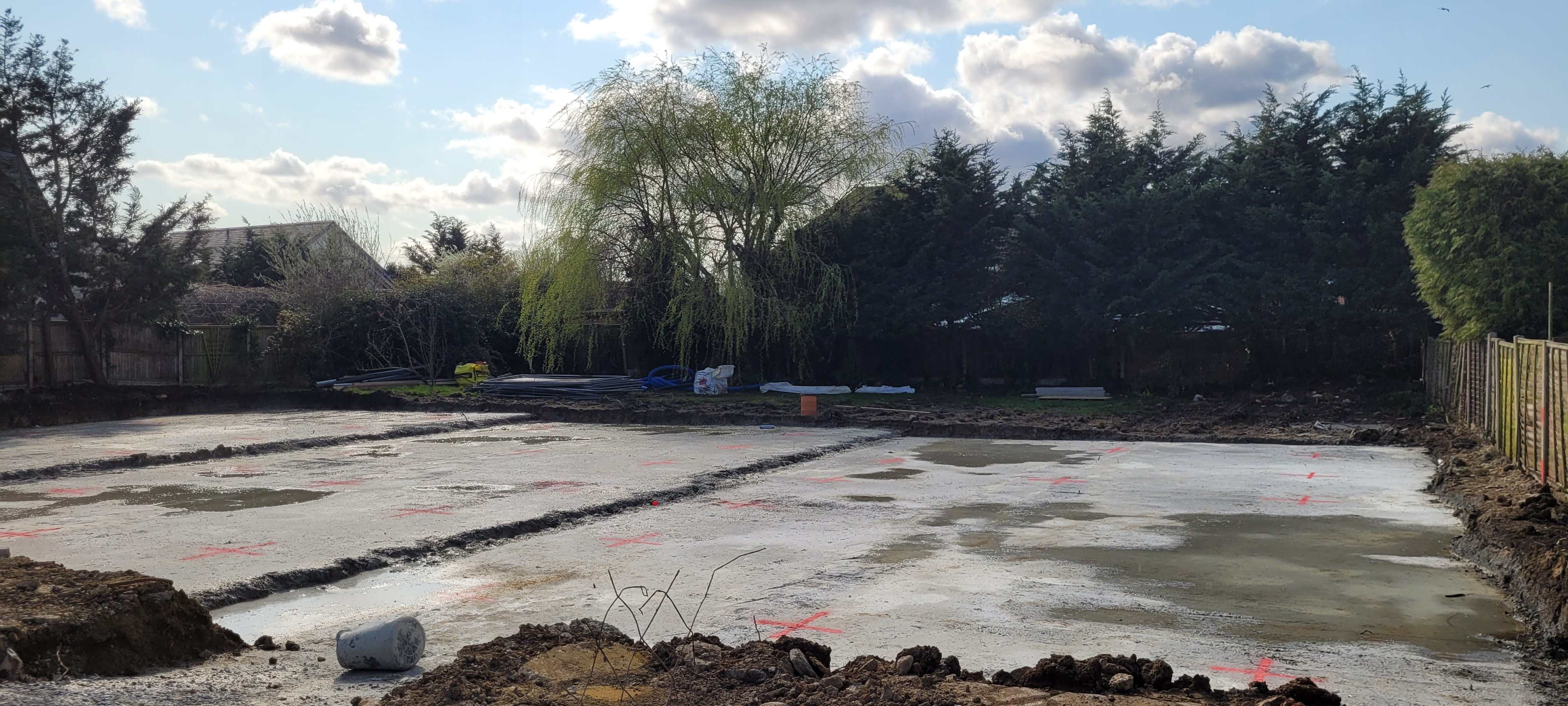
Round the corner from us they ar building 3 houses on a single plot. They have scrapped out three levels - the road rises past the plot, without any trenches just flat. On Thursday I noticed they were just pouring concrete onto these three flat levels, no services- nothing, you can see from the picture below what that looks like. Are they just short circuiting the passive slab build up to do without the N layers of type 1 and the pea shingle sub-base without any peripheral drainage or what what is going on top of these ponds of concrete?
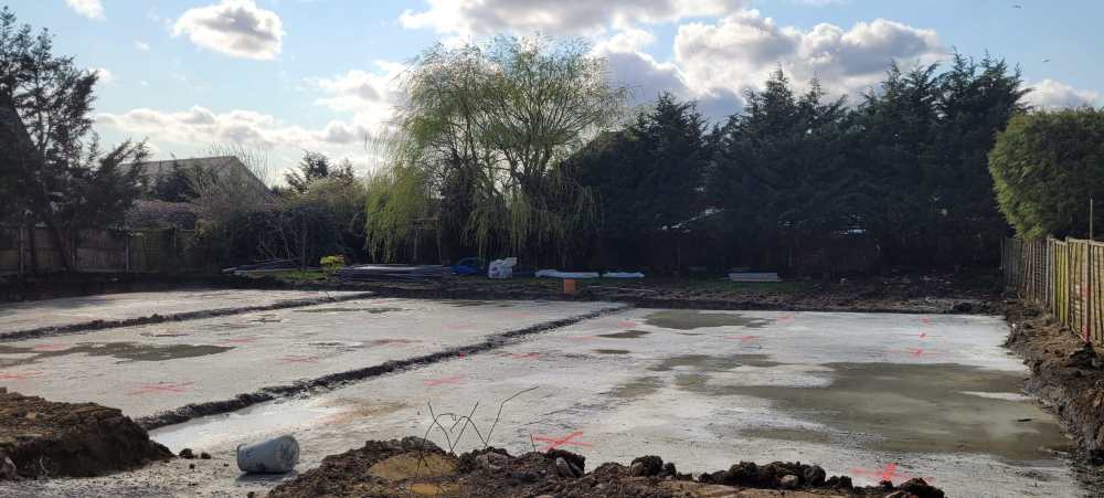
-
Are you happy with it - in terms of the service it delivers, air quality etc?
-
Best pipe insulation and where do I need it?
MikeSharp01 replied to MikeSharp01's topic in General Plumbing
Yes so you pump hot water round the house with take off points at each sink, shower etc returning it to the tank. Its much more common in commercial buildings but if you have it it means the Hot water is almost instant at your tap! It is costly in energy terms and if you have it then very good insulation is needed for the pipework especially in a highly insulated house. -
Exploring the ratios and losses between building elements
MikeSharp01 commented on SteamyTea's blog entry in Energy Ideas
Two things arise in my head from this - I may have missed something as I did have some wine last night. Firstly, if it is a big problem why has it not been sorted out - stupid to ask I guess but hey. Secondly, if you do have a blower test result then surely the leakage must add to the MVHR losses and be a calculate fraction assuming the MVHR holds the pressure difference roughly constant. From this it must follow that you can reduce the MVHR setting by the pressure test ACH when you are setting up the MVHR as part of the ventilation strategy. Might this then go some way to explaining why people find that when using MVHR they can back off the flow rate and still be comfortable because all they have done is got to the regulation ACH flow rate including the fabric losses. -
Shocking Snagging Inspection Finds at NEW BUILD HOMES....
MikeSharp01 replied to MAB's topic in Housing Politics
They think they are getting a trouble-free house with no work to do, the horror stories won't happen to them, and anyway, there is a 10 year guarantee. What they don't know is that the guarantee is mostly worthless, the horror stories happen everywhere, and the house will be poky and the same as the one next door without any character. -
Closing this Thread as there is a better one here:
-
ooops I didn't spot that?
-
Got a letter from Pete t Octopus today telling me that as of 1st March our feed in tariff will drop to 12p / kWh from 15. They are offering agile export as and alternative but are there any better rates out there I wonder?
-
Why did you choose an air source heat pump?
MikeSharp01 replied to SimonD's topic in Air Source Heat Pumps (ASHP)
We started the build as a Passive House but gas fired, we had the gas laid in and ran the track pipe (which is for sale in the market place now.) through a duct from the gas meter. I had looked at ASHP but felt gas was a safer bet, this was at the planning stage in 2017 - we wouldn't need a cylinder so the heat loss into the building, which @Jeremy Harris had shared with us all would not be a problem. I had a very good plumber / gas fitter so fitting the boiler would have been no problem and it should have been a smooth process with a combi boiler. Then I started to get much more concerned about the eco credentials of gas fired heating and decided to look at other options SUNAMP, PV, Willis, and battery but as SUNAMP was getting increasingly bad press and the Willis route would have hit our SAP score they got kicked into touch. So gas came back, but sadly our tame gas fitter was taken ill, and was unable to work, and we would have had to seek someone else so I took a look at ASHP again, plus the grant was now £7500 so we should be able to get it done for that! So in 2021 we started looking at MCS installers and that was like pulling teeth because none of them were very convincing and didn't listen to our design and insulation standards preferring to fall back on some sort of opaque arbitrary process to give us wild quotes for a straight install where a big chunk of the work was already done. The UFH is in and I had installed two 28mm pipes in the insulation from the utility room to the place we might install a heat pump just in case. So again I swithered a bit, and at that point the Umbrella schemes started to take off and it struck me that we might fit the ASHP ourselves if we could find a sound scheme to duck under. In the end after a lot of searching and a bunch of Quality Function Deployment (QFD) like exercises to compare the various offers we went with Cool Energy, although we had to wait almost a year for their smallest Heat Pump to get MCS accreditation. Its installed and commissioned now - still sorting out some teething issues, we have had our grant money and the all up cost with everything including the EMON heat meter system with all the bells and whistles has come in on the money with me doing all the plumbing, electrics and controls and them signing it all off. -
Interesting couple of days with the new heat pump.
MikeSharp01 replied to MikeSharp01's topic in Air Source Heat Pumps (ASHP)
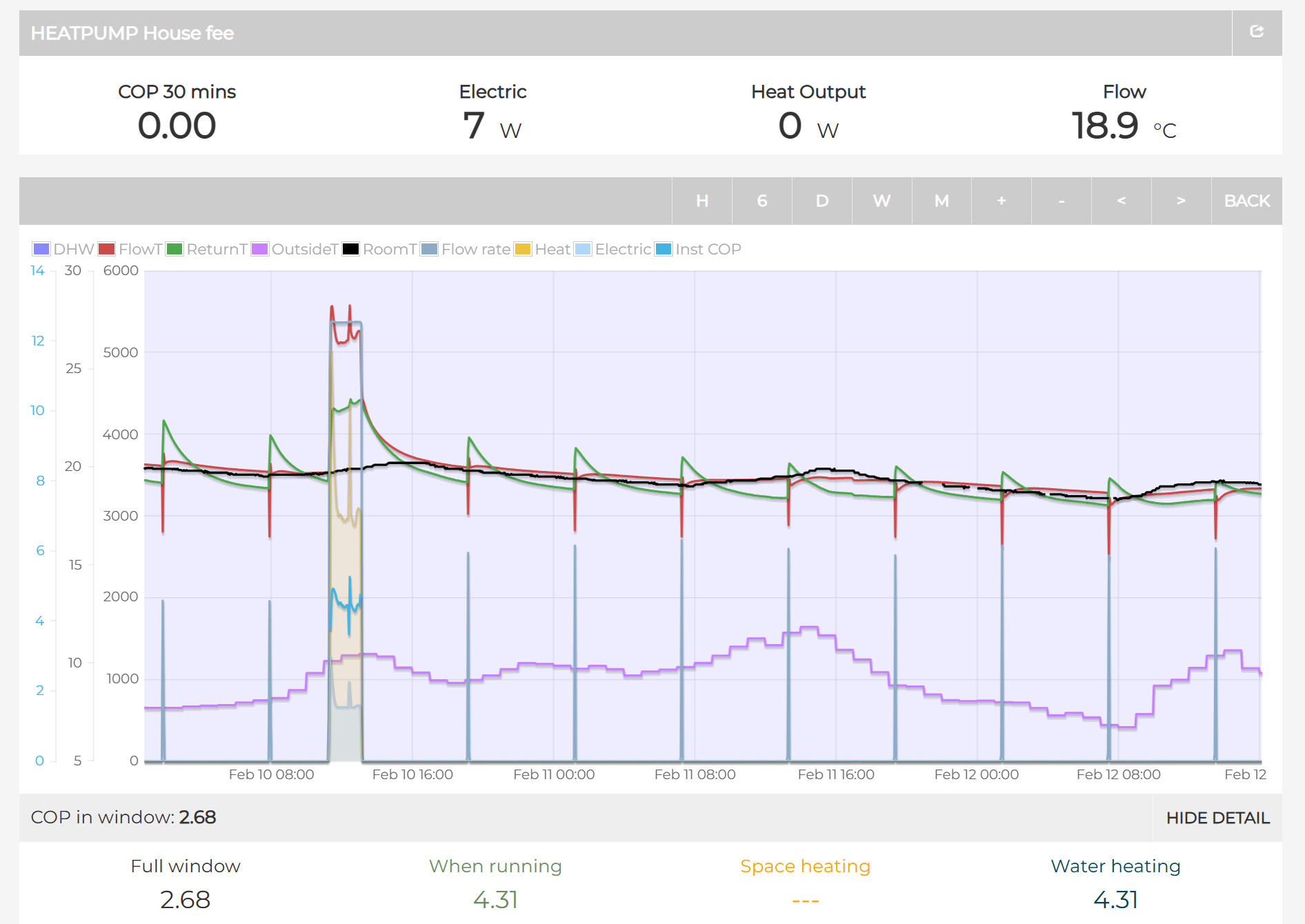
It's been a busy weekend family wise so have not had a chance to talk about any issues but you may have hit upon one I saw on Saturday. I was running with normal settings 28 degree flow and trying not to fiddle so as to limit the number of variables as @SimonD encouraged me to. (Remember I am not using WC as I cannot control the end points of the curve yet and I am awaiting a response from the manufacturer as to how to set them - hopefully tomorrow.) and for some reason at 12ish the system just stopped. Well when I say stopped I mean it stopped producing heat and just ran the pump. Those dips at about 12:30 & 13:15 are me turning off and on again - making no changes. It was a sunny day so the room temperature is rising as is the outside air temperature (OAT) but the heat pump (HP) knows nothing of the Room Temperature and it has no 'stat' anywhere. Initially I thought that the problem was the OAT sensor of the HP because it is in direct sun - something that will be sorted when the bin house is complete but for now I may have to shield it. It was up at 24 deg C. So I left it and went out for the afternoon with my Valentine! Came back at 5 and tried to start it, now the OAT sensor was normal, about what the EMON trace shows (remember that the EMON trace is derived from the local weather station). Still it would not start and I was now quite worried - I have broken it! However at 18:00 I thought OK lets see what happens if you call for a domestic hot water (DHW) cycle. That started first time so the main workings of the HP are in order something else must be preventing it from delivering heat. Anyway while watching some telly across the evening I just prodded it with reductions in the flow temperature, a few times to no avail. I slept on it and this morning I decide to go the other way - upped the flow temperature setting to 31 and off it went. Nothing broken but something odd going on - now all I need to know is why this occurred. Reflecting on it all I think there are aspects of two things hitting the issues in this chart. The first is the OAT sensor - If it gets too hot it won't allow the HP to run anything but the pump, so I am going to have to shield it for now. ( I do assume it will allow the DHW cycle to run however even though I did not try this.) This ties up with your experience above @JohnMo. Secondly if the delta (Δ) T is less than some value, I think around 5, it won't allow the unit to start although it might allow less if it was already running. So as I lowered the setpoint down in the evening it was too close to the return temperature because the slab (hovering across this whole period at around 22 deg C) was feeding back return water at too high a temperature. If I increase the setpoint enough it would start without issues. I managed to trip the same behaviour on Sunday evening and it is clear that for this heat pump it won't start if the return temperature, after perhaps couple of minutes of the pump starting up, gets too close to the set point the pump won't start but that you can get it to start by upping the setpoint, letting it run for a few minutes and then backing the set point off to where you wanted it to be in the first place. So now all I have to do is find out what setting(s) causes this behaviour, perhaps its some sort of overlap between dead bands somewhere in the system or some such. I don't think we can turn this off on ours but I have to say I have not seen much, if any, modulation in output below about 3kW, I will hunt through the trends data and see. I already have all the flow meters wide open.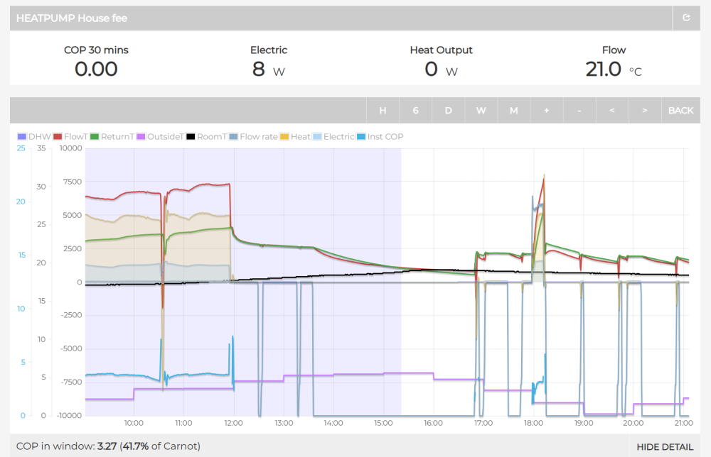
-
Target U-values… Cost/benefit sense check… What am I missing? 🤷🏻♂️
MikeSharp01 replied to fatgus's topic in Heat Insulation
True payback can be long although it seems that payback is not always a good reason not to do it because the 'value' dimension gets lost. So while you can know both most people know the cost of things but cannot articulate the value. I suspect that if you stand back far enough on the payback side only in £ terms you will be hard pressed to make self building pay back. -
You cannot realy believe that because you already have a lot of automaton in your house it's just not all joined up with a unified majordomo. So it's all about where you are in the automaton onion layers, where you automate everything on the outside and you just have digital thermometer on the inside. Between them are just layers but if you peel down the layers it still looks like any other onion. So home automation is about layers, if you have anything automatic you must have home automtion. QED
-
Interesting couple of days with the new heat pump.
MikeSharp01 replied to MikeSharp01's topic in Air Source Heat Pumps (ASHP)
I need to look at the Agile tariffs to help once I get it settled down and have the full BMS integration details. As it is I only have the read codes for the Modbus link. So although I can turn it on and off using the call for heat contact I cannot switch modes to DHW other than at the controller itself so not much good for the agile tariffs. -
Interesting couple of days with the new heat pump.
MikeSharp01 replied to MikeSharp01's topic in Air Source Heat Pumps (ASHP)
I think the 70T is the whole structure without the cladding or insulation. The slab is 100m2 at an average depth of 200mm so 20m3 of concrete. Which interestingly is what it says on the slab concrete bill IIRC. So 50T inc the steel or there abouts. Its been too hot in here for the last two days. I have added no heat in since the 10th and what with solar gain, high local temps, and me working at plaster boarding, the temperature today is 0.7 oC lower than it was on Tuesday when I turned it off. 19.9 when I turned the heat pump off and 19.2 now! Can I be impressed with that? The slab has lost 2oC over the same period and is now at 19.44oC so perhaps some charging will be needed as the whole house drops together.
-
Interesting couple of days with the new heat pump.
MikeSharp01 replied to MikeSharp01's topic in Air Source Heat Pumps (ASHP)
Yes I get that and I was only Joking anyway. Yes I am being now as the house is too hot for heavy plaster boarding so I have left it off while I await the technical curve setting details. Even leaving it off is quite instructive though. the slab has lost 1 degree in 24 hours with an external temperature (OAT) of 10 degrees form 21.5 - 20.5 while over the same period the room temperature has dropped slightly less - could be because I was working in there today. -
@Jeremy Harris played with those although I think he just used them to boost the hot water at the end of the HW run. I dimly recall he gave it his best shot but in the end removed them as they didn't meet his need.
-
Two questions relating to UFH manifolds
MikeSharp01 replied to Bancroft's topic in Underfloor Heating
Ours is 1.2kW at -3, half that is 600W is there such a Heat pump? - I think your latest goes down to 1kW, ours only goes down to 1.8kW. We are still a long way from COP of 6 although today I was playing again and I managed a short run at 5. -
Whole house Audio one presumes, is that for making sure the same music is everywhere.
-
We are always interested on here. Sometimes driven by pure schadenfreude but mostly because we know we will go, or have already been, there.