MikeSharp01
-
Posts
5693 -
Joined
-
Last visited
-
Days Won
16
Everything posted by MikeSharp01
-

So to today's questions on our ASHP install.
MikeSharp01 replied to MikeSharp01's topic in General Plumbing
That's already on the top of the small vessel should I also fit one to the big one? -
So to today's questions on our ASHP install.
MikeSharp01 replied to MikeSharp01's topic in General Plumbing
The Umbrella company are doing that alongside the MCS cert, hence me asking all the questions so I get it right and don't end up with problems. -
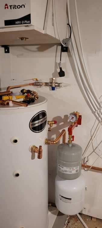
I am working on the tank end of the system now and that has thrown up some clarifications that I need to be sure of: Can I install the Thermostatic Mixing Valve (TMV) upside down as shown in the picture. (Cannot see what gravity has to do with the operation of such a valve) In connecting up the various overflows and the condensate drain from the Mechanical Heating and Ventilation Unit (MVHR) above the tank I need to get the final output into our main soil pipe. How far should I run it in copper? (As far as possible as you want it to cool down before it hits any plastic) How important are the details of the runs to the tundish(s) - seems like there is supposed to be 300mm of straight pipe into it etc... (I need to get the three pressure, one of which also has temperature, relief outflows into the pipe above the tundish.) Or would it be better / acceptable to go for three tundishes and join the flows below them? How do I connect copper to 32mm waste pipe? (Cannot seem to find a connector for this - do I make one from a blanking cap and tank fitting or some such? I did find this https://www.toolstation.com/tesla-tundish-universal-dry-trap/pAG239 but that goes directly from Tundish to 32mm so no room for cooling.) Can I get away with a waterless trap or do I need a full U bend in the plastic bit? (Waterless makes sense because it will get very little use so a U bend could / would dry out) Is there a waterless trap for 22mm Copper perhaps? As you can see from the image I have not yet connected the Heating loop from the ASHP to the expansion vessel. I assume it does not matter where in the heating circuit I make that connection as pressure difference arising from heating in the Domestic Hot Water (DHW) Loop and the UFH loop will manifest itself everywhere in the circuits. (I have no room for the expansion vessel elsewhere but I can run a long pipe to it from wherever in the circuit if needs be.)
-
Utility connection costs
MikeSharp01 replied to Saints1's topic in General Self Build & DIY Discussion
They sound about OK to me. Our costs were (IIRC): Re-route Electricity from old house overhead to utilities block by the pole (pole on our land) down the pole along a 400mm trench, which we dug, and up into the meter box: £1200+VAT (2018) Move gas from the old house, which we knocked down, to utilities block in trench we dug and then remove it completely when we decided not to have gas £840+VAT (2018 / 2021) Do you really need Gas, might be worth working out if a ASHP might be a better solution if you are building a well insulated / air tight property. -
I like that you have Ned Kelly wearing his metal head gear working there in the middle with the green high viz.
-
Metric.
-
Today's heat pump install questions!`
MikeSharp01 replied to MikeSharp01's topic in Underfloor Heating
The thread on gauge does not appear to be standard, 1/8th BSP vent does not fit, I will talk to the suppliers and get a new end cap assembly as the flow head. -
Today's heat pump install questions!`
MikeSharp01 replied to MikeSharp01's topic in Underfloor Heating
Sadly that would require a complete redesign and there are loads of other pipes - mains water, water softener etc, running in those areas I have not installed yet so two filters is easier. I have the connections for that coming Monday to the far left of the straight run from the return manifold That's already in the return line from the tank out of shot to the left. Its not 25l though it 8l which should more than cover the 70l of the system I worked out. -
Today's heat pump install questions!`
MikeSharp01 replied to MikeSharp01's topic in Underfloor Heating
Here is the plant room mockup plumbing (used 28mm plastic segments to get lengths right and check scheme). I think I can get the filters into the utility room as indicated, I either do away with the fill flush or put it outside by the HP and work hard to insulate it.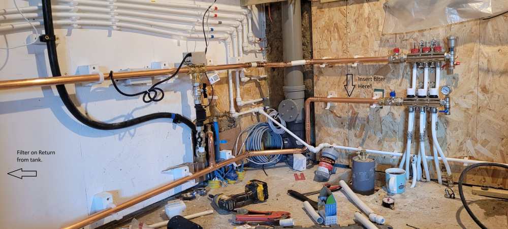
-
Today's heat pump install questions!`
MikeSharp01 replied to MikeSharp01's topic in Underfloor Heating
I will send some pictures in the morning. -
Today's heat pump install questions!`
MikeSharp01 replied to MikeSharp01's topic in Underfloor Heating
I think I have a full flow filter. It's this one: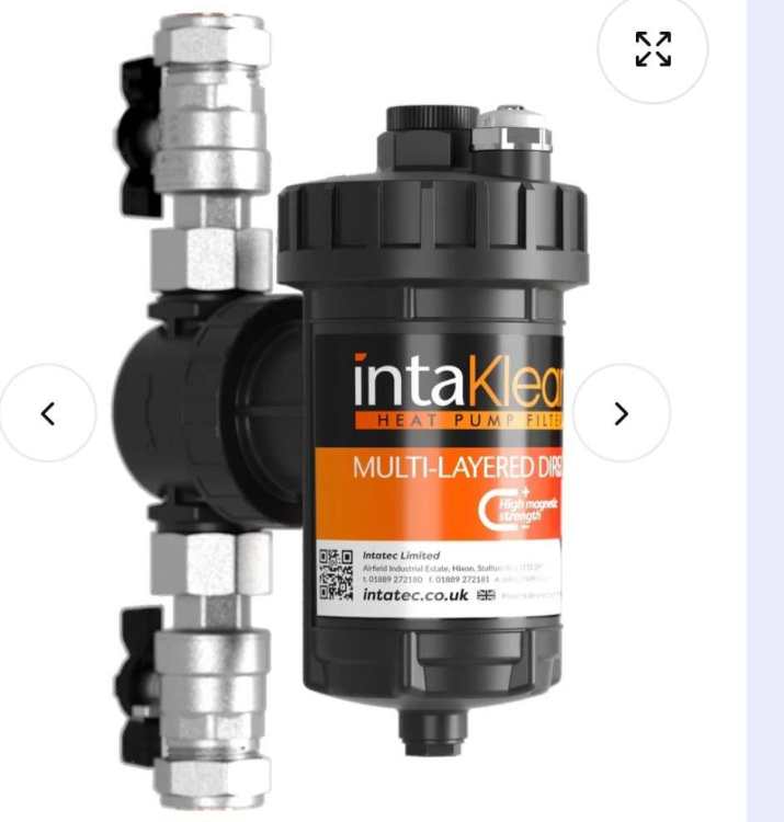
-
Today's heat pump install questions!`
MikeSharp01 replied to MikeSharp01's topic in Underfloor Heating
So I am going to have house them both outside. -
Today's heat pump install questions!`
MikeSharp01 replied to MikeSharp01's topic in Underfloor Heating
Thinking about it I cannot put the valve inside either as it would have to be in one side or the other of the system. -
Today's heat pump install questions!`
MikeSharp01 replied to MikeSharp01's topic in Underfloor Heating
Does that mean the stainer has to be inside as I have nowhere to put it inside. Pipework splits as it comes through the wall. -
Your budget is not unrealistic for 80m2 and if you are into it for the long term you can do a lot of the work yourself and pay for it as you work. The up front lump will be your plot cost!
-
Today's heat pump install questions!`
MikeSharp01 replied to MikeSharp01's topic in Underfloor Heating
Thanks, how do you put inhibitor etc in, no Glycol. We are but the manifold went in before we chose to go that way, only three loops no independent control of the loops other than by the flow meters which once set are left. That is what I thought. -
Looks like the party is over....
MikeSharp01 replied to Beelbeebub's topic in Air Source Heat Pumps (ASHP)
Radical Thinking - but maybe where we are heading. Our children, in their 30s, will defo not retire before 70! -
Making progress we are but have a couple of questions. Can we install the fill / flush valve: outside by the heat pump, much easier to get at if we can, just needs good insulation around it and I guess I will still need a filling loop inside to pressurise the cicuit. Each of the UFH loops have a control valve at the bottom and flow meter at the top which way do the control valves work, unscrew to open or screw down to open. The rep from the company did not know but their technical guy has yet to get back to me, thought there is bound to be an expert here somewhere. Do I need Non return valves (NRVs) in the return circuits, UFH and Cylinder, before they re-join to go back to the Heat Pump, I can't see why I would but I saw somewhere doing it.
-
Welcome to THE forum for people like us. Well 3k per M2 is not a bad figure, so yes. On question 2 I have no idea.
-
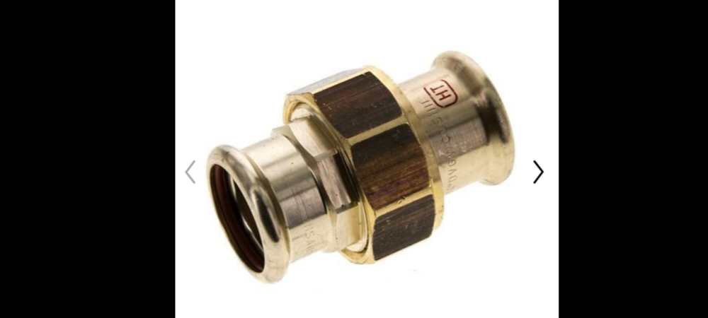
To make getting some of our 28mm heat pump pipework accessible after install I am looking for a couple of flat face connectors so I can break the joint and remove pipes sideways with out having to unplug lengths of pipe in the fitting; This one looks good but is not a traditional compression at either end. Is there such a thing out there?
-
Any love for CCT (i.e. changeable white) LED strips?
MikeSharp01 replied to Alan Ambrose's topic in Lighting
What does the LGBGT stand for here cos I am blowed if I can track its meaning down. -
Payment Terms - Pay everything upfront?
MikeSharp01 replied to Mulberry View's topic in General Self Build & DIY Discussion
We used Norrsken and had the same basic worries so we split the contract so that no single part was above the 30K limit on the Credit card protection which made me feel better. As with Nick they did a grand job and came back promptly to fix an issue with one of the seals jumping out of its slot. -
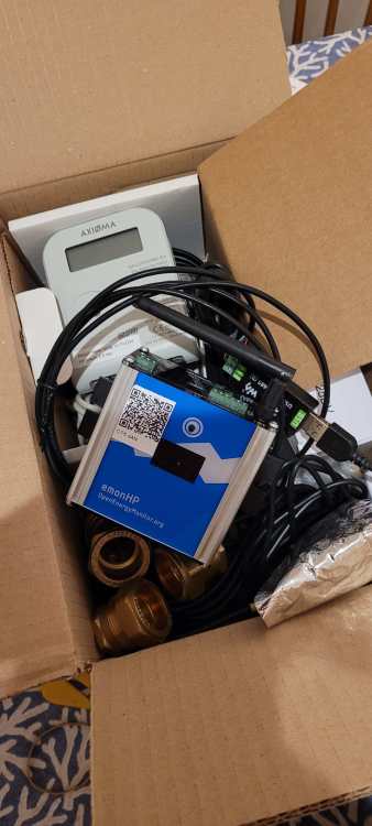
Today's learning point is this. The heat meter arrived yesterday and very smart the OpenEnergyMonitor.org Level 3 system is! However pasted across the flowmeter port is a sticker that says '1.5bar minimum pressure' which gave me cause for concern because our system only has a 9m head pump and in normal operation we will be using only 2.7m of that at 5oC delta T (5.57m at 3oC delta T) which is only about .25bar. So I called the suppliers and asked how this would work and got a simple, but not obvious to me, answer that you need to pressurise the system first. Reflecting on this news I think I get why the system might need a base load pressure. To ensure positive flow to each circuit giving the pump a stable operating point. Stop cavitation in the pump Remove the possibility of negative pressure sucking air into the the system. If that make sense the only question now is what pressure to set it at? 1.5, 3 bar or some other value?
-
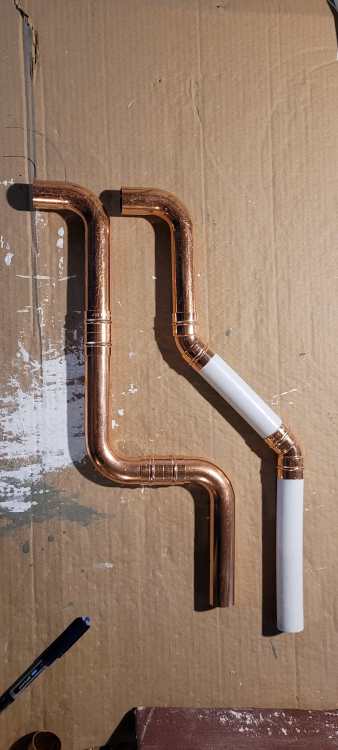
Bending 28mm pipe sounds like a challenge, I got the swept bends in the images to avoid bending myself. I do have a conduit bending machine but I am not sure I can get a 28mm former for it - I will have a look.
-
Yes John and I realise I could simplify further as this image: