Jeremy Harris
-
Posts
26430 -
Joined
-
Last visited
-
Days Won
360
Everything posted by Jeremy Harris
-
I suspect you're right. The action of the Finder contactor was always a bit violent, in that from new it made a hell of a clunk as it operated, enough to wake the dead. I've got a four pole 20 A contactor running a couple of socket radials in my workshop (I have E stops around the place to kill the supplies) and even that doesn't make anywhere near as much noise as the Finder one used to. The ABB one I've just fitted is a fair bit quieter, too. Makes me wonder if the Finder may have had an incipient mechanical defect from new, given the amount of noise it made.
-
 Good illustrations of a point that @Nickfromwales has emphasised a few times, that tiles laid on a boarded floor need a layer of glued and very well screwed marine ply fixed to the floor, to reduce the risk of movement. I glued and screwed 9mm marine ply to both our upstairs bathroom floors, making sure that the ply joints were well staggered away from the underlying flooring joints. This seems to make for a very solid floor, but I did use lots of PU adhesive and hundreds of screws, just to be sure as I could that it wouldn't flex, as our flooring up there is 600 x 400 travertine, which needs good support.
 -
Just been testing the defective Finder contactor on the bench. It seems to have broken mechanically, as when the coil energises the over-centre mechanism tries to move, makes a loud clunk, but jams. There's a mechanically driven indicator on the top, and this barely moves, whereas it's supposed to flip and show a red flag to show that the contactor has energised. Also, it rattles a lot, as if there are loose bits floating around inside. I'm tempted to take it apart, but that would mean drilling out two rivets, and I really want to get this replaced by Sunamp, given that the ABB one I've just fitted cost ~£30.
-
The neon series resistance is about 330k, but will appear higher, as the neon will be running at around 60 VAC or so, so the current drawn by the indicator will be well under 1 mA (I might measure it later). The current drawn by the coil is about 22 mA, and has a tolerance of around +/-5%, so, depending on the exact part fitted, it could vary from just under 21 mA to just over 23 mA. That's more variation than there would be from adding a neon indicator. Anyway, the source supply is a fused 3 A supply switched by a 16 A relay, so there's never going to be any measurable difference in the voltage across the contactor coil, just from that connection being loaded by another half milliamp or so.
-
Thanks! This looks to be the controller that Andy Trewin was talking about last time I spoke to him. I think he has this controller, as he was telling me that he can get any information he wants from it. He no longer works for Sunamp, so he didn't know anything about the controller we have, or why Sunamp seem to have changed the design. I've been in touch with others who have Sunamps and Andy Trewin is the only one I know of that has a more complex controller. It's hard to see how. The contactor is switched by a relay (one of these: https://uk.farnell.com/te-connectivity-schrack/rz03-1a4-d012/power-relay-spst-no-12vdc-16a/dp/1844686 ) that switches mains straight from the always-on supply, and that relay is rated at 16 A, so an additional current of a bit under 1 mA to supply a neon indicator isn't going to have any impact. The relay on the controller circuit board seems to be massively over-rated for something that only switches a contactor on and off, I'm not sure why they chose to use a 16 A rated relay when they are only switching about 22 mA.
-
They will find themselves in one heck of an argument if they do! Given that a contactor has to provide isolation between the coil and the power terminals (the Finder one they fitted is is specced to 4 kV between coil and contacts) there is no way that anything connected to the coil terminals could possibly affect the contacts.
-
I can easily do this, but I'll hang on until I get the new controller from Sunamp (they are sending out new controllers to some customers, it seems, including us). As I understand it, the new controllers they are sending out still have no form of external indicators. What I think I'll do is fit a couple of indicators to a blank face plate, with labels, and a cable back to the Sunamp controller. I reckon that having three indicators might be enough, one to show that the power is on, one to show if the contactor is getting an energise signal and one to show when power is on at the contactor load side. It might be OK with just two indicators, an incoming power indicator and a heating element power indicator.
-
Yes, they were, also the colours were easier to distinguish. I can think in the old colour codes, and look through a box of resistors and subconsciously view them in terms of value, without having to think about converting colours to numbers (might be a side effect of synesthesia, though, as I think of words as colours anyway, today is black, being Sunday). The newer, dark coloured, resistors, with the new (well, ~20 year old now) colour code are a lot harder to decode, and often seem to need both mental effort and a magnifying glass. I find the new brown and red bands particularly challenging to distinguish. I'm not colour blind either, but can sense what it might be like to be colour blind when trying to decode these, especially some of the dark background MF12 series ones.
-
Not sure what that controller is for, TBH, as it looks nothing like the controller for the Sunamp UniQ we have. It looks as if it can control a whole heating and hot water system to me, which is interesting. The controller we have is a lot simpler, and just has three temperature sensors inside the heat battery, a small board with the control electronics, and a contactor on the DIN rail with all the other terminals. I think the old Sunamp PV was fine on hard water, as they were initially concerned that softened water might cause a problem, which is why they wanted our old unit back, together with a sample of our water, to cut the thing open and see how it looked inside, after nearly three years of use. We now have hot water back, thankfully. There's enough excess PV generation to start the Sunamp charging, and the water's reasonably warm. I'll definitely keep an eye on the contactor for a while, and might add another neon indicator to show when there's power going to the Sunamp heating element. The lack of any sort of status display on the Sunamp UniQ series is a real PITA, as you have no easy way to see if the thing is working properly. The Sunamp PV was great, as it had four status LEDs on the side, so you could see at a glance what it was doing. Not fitting any sort of status indication at all to the UniQ range seems barking mad to me.
-
I'll make sure I keep a stock of spares... It's damned lucky that I happened to have that new ABB ESB 20.20 contactor sat in my "may come in handy" box. It's a spare for the contactor that switches our water pump on and off, so I'll now have to go and buy another one to use as a spare.
-
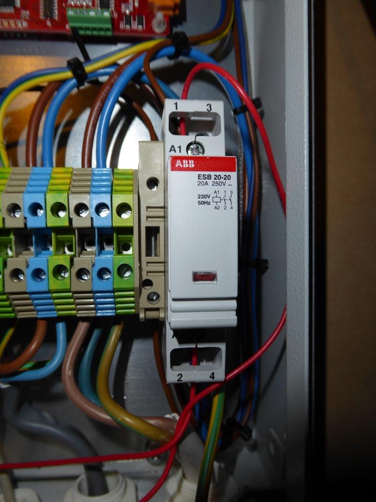
Me too. I tend to always use decent brand name stuff where I don't want failures (or fires...). This is the new ABB contactor in and working (excuse the untidy red wires, they run to my add-on neon indicator to show that the contactor is on):

-
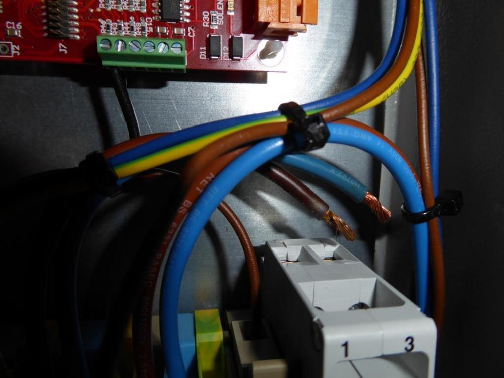
Good news! Fitting an ABB 20.20 contactor has restored normal service, and the unit is now charging up again. I'd like to take the old Finder contactor apart, to see how it's failed, but fully intend to get Sunamp to sort this, as I don't see why I should have to put a replacement £30 contactor into their 6 month old box. It's normal to use stranded equipment wire in stuff like this, makes it a lot easier to wire up. However, it's also good practice to fit insulated wire ferrules at screw terminations (should be made mandatory in my view). This is what happens when people choose to wire up fine stranded wire without using ferrules (look at the end of the line connection):
-
Just pulled the contactor out. It's a Finder 22.22.8.230.4000 and it's definitely buggered (this is the thing: https://uk.farnell.com/finder/22-22-8-230-4000/relay-dpst-no-250vac-20a/dp/1169295). Looks like it's been overheating slightly on the line in terminal, although all the screws were tight. The closest I've got to this is a spare 20 A, DP, ABB contactor, rather than the 32 A ones I use in the car charge point. ABB stuff tends to be a bit better than Finder stuff, IMHO, so having checked that the spec looks similar I'm off to fit the new one and see if that fixes things. (Note to self: Don't assume that zero amps on a clamp meter in the supply to the heater, with power on and a contactor apparently closed, means that the heating element is open circuit in future...) PS: There are NO ferrules on any of the wiring that Sunamp have done. I think that this may be a contributory factor, as they've used fine stranded equipment wire poked straight in to terminal, pretty crappy workmanship in my view (I always use insulated ferrules when terminating stranded wire, have done for years, as I've seen too many failed connections at screw terminals in the past)
-
Great minds think alike... I have managed to get at one of the cover Allen head screws and undo it, so that I could just pivot the cover up. I have a USB endoscope that plugs into my tablet, so used that to find the trip, and found that it doesn't seem to have operated (I can't quite get my hand in there, but it looks like the button is down). The contactor in the controller is clonking as normal, but having just checked it I've found that, under load, it's open circuit, so it looks like the contactor has failed. Luckily I have some spare 32 A DP contactors, that are a bit larger, but are also DIN rail mounting so should fit into the controller box (they are the ones I've used for my electric vehicle charge points; I keep spares just in case). Just off to change the contactor and see if this fixes things. I'd be tempted, as that looks like an old Sunamp PV to me, but if so then it's really about 4.5 kWh, with a 3 kW heating element. At £700 it's not a bad buy if it's new, as they retailed at around £1600 IIRC. If I was given two of those instead of the Sunamp Uniq we have I'd take them, no question, as my experience of the Sunamp PV was that it was very reliable once the initial bugs were ironed out (our Sunamp PV was accepted as a pre-production unit that may have a few initial issues that might need fixing, anyway).
-
Right, I may be gone sometime, as I'm going to try and gain access to that area by disconnecting and moving the water softener (easier job than disconnecting and moving the Sunamp). I'm hoping I can get just enough room to get my hand in and feel for a trip somewhere.
-
Yes, that's right, and the image above is the left most one in Fig. 5.1, which mentions an overheat thermostat. The three sensors are fitted into a tube in the top of the unit, and are easy to access, but it looks like the overheat trip may be somewhere in the base of the thing.
-
I agree, but there's nothing in the manual apart from this photo with the (only) mention of there being an overheat thermostat (this image is as clear here as it is in the manual): I've just found this mention of the overheat thermostat from @Nickfromwales, which supports the view that there maybe a resettable overheat trip (rather than an overheat thermostat, which would automatically reset) in the base of the unit: The next challenge is to gain access to that area, then try and grope around in it to see if I can find anything that feels like a trip. This is going to be a complete PITA to do, though, just because there's no mention at all in the manual of needing to gain access to this area, let alone any mention of what's behind the small cover on that side.

-
I've been looking through the various versions of the manuals I have (three different ones now) and there is a blurry photo with a label on it showing an "overheat thermostat". There's no mention of this at all anywhere else in the manual that I can see, but (clutching at straws here) I'm wondering if it may be a resettable over-heat trip? The photo is dreadful, and doesn't actually show the thing at all, just a blurry aperture in the side of the unit. Unfortunately that side of the unit is hard up against a step in the floor, on which our softener is mounted, so to get at it I'll need to turn off the water, drain down and disconnect the Sunamp and move it to gain access (not easy, it weighs over 150kg). Has anyone else here had a problem like this, or know if there is an overheat trip that can be reset? It would be great to know if this is the case, as it's going to be a PITA to just gain access to this area to have a look.
-
Accumulator or Pump to boost water supply?
Jeremy Harris replied to Ferdinand's topic in General Plumbing
There aren't any regs for an accumulator, and they are almost fit and forget. They can lose precharge pressure over time, and the internal bladder may need replacement after a decade or so, but it's pretty easy to keep an eye on the pre-charge pressure from time to time and make sure things are OK (no different to checking tyre pressure, as they use the same valve). -
Cold showers again this morning. It now seems our Sunamp is dead, as although the contactor was on, the heating element isn't heating up. We are not happy bunnies right now, especially as this means cold showers until such time as the thing gets fixed. I've checked and the wiring to the heating element appears to be open circuit, which doesn't bode well for a rapid fix to me. I did think it had charged up quickly in the sun yesterday morning, too, as we were exporting by around 09:30, whereas I'd have expected the Sunamp to still be charging. I should have investigated further then, although I'm not sure what, if anything, I could have done about it. Right now I'm beginning to wish I'd never changed from the Sunamp PV.
-
Septic Tank v Sewage Treatment Plant
Jeremy Harris replied to canalsiderenovation's topic in Waste & Sewerage
Cess pits have no drains, so fill up two or three times a year and need to be emptied. A septic tank will have a couple of internal chambers, with the second chamber, downstream of the internal weir, being connected to a leach field. -
Septic Tank v Sewage Treatment Plant
Jeremy Harris replied to canalsiderenovation's topic in Waste & Sewerage
All tanks and treatment plants will end up with sludge in the bottom that never gets digested, pretty much the same as the human digestive system, really. Actively aerated treatment plants tend to generate less sludge, because they use the aeration to lift sludge up from the bottom and keep it circulating, so more of the digestible stuff can be consumed by the bacteria in the thing. -
That's a good point. The chap I knew with the Lister generator set up had it in a purpose built concrete block building, about 8ft square. He built the building on a substantial concrete base, that included the buried, and cast in, underground oil drum silencer. He made the walls from a single skin of blocks laid on their side, with the roof made from pre-insulated corrugated steel sheets. The exhaust went out through the roof, with a conical rain hood on top. He dry lined the inside of the shed with some sort of composite timber sound proofing board, stuff with loads of holes in it, although the only real noise from the Lister is the clatter from the valve gear. He could get around 4 kW or so from the generator, so enough for a basic house, with a bit of care in managing the demand. Servicing will be a lot more often than annually for a regularly run gen set. People I know who live off grid do basic servicing checks every week, with oil and filter changes every couple of months, and a cylinder top end overhaul every year or so (lightly loaded generators tend to coke up the exhaust port and injector). Petrol generators need less maintenance, but cost a great deal more to run, plus they don't last very long at all. A regularly used petrol generator may need replacing after two or three years, plus, based on my experience with petrol generators, I'd say that reliability is a significant concern. Whereas a heavy diesel will be very reliable and run for thousands of hours with just a bit of light, regular, maintenance, I've yet to see any petrol generator that's reliable in the long term.
-
@NeverEnoughCake, I think most here (including me) would like to see you succeed in living off-grid, but equally some of us have experience of what it takes to do this and may think you're being very optimistic about what you'll need. Everyone I know who lives off-grid has ended up with larger and more complex systems than they originally envisaged and all have spent way more than your budget (with one possible exception). If you really want to go off-grid on a tight budget, then I would consider just scrapping the idea of a tiny and expensive battery and PV system, and instead invest in a reliable, and cheaper to run, low speed diesel generator, at least as an initial starting point. A chap I knew quite well where we used to live, chose to have his house disconnected from the grid, after he installed a single cylinder Lister (really an Indian Lister copy) generator, as a combined heat and power system. His generator is in a block built shed, with a buried silencer (just a 45 gallon drum with two pipes, buried in the ground) and is very quiet when running. He runs the generator on waste vegetable oil (WVO), that he collects (given away free) in drums from a local chip shop, a fast food place and a Chinese restaurant. The Land Rover that he uses to collect the WVO runs on biodiesel he makes himself from WVO (pretty good recycling). He runs the radiators in his house with waste heat from the generator, as it's water cooled. He's also added a simple heat exchanger to the exhaust of the generator to recover more waste heat. The whole set up is very reliable, and seems to provide him with all the electricity he needs, as well as providing background heating to the house. He shuts the generator off at night and starts it again the next morning, and hasn't seen the need to fit a storage battery at all (all he has is a starter battery for the generator, AFAIK). The engine he's using is a very tough, long-lived, one, that has a reputation for longevity (50 years isn't uncommon for these). There's a fair bit of information on the internet about these big Listers, as they are popular amongst off-gridders. The Indian versions are generally referred to as "Listeroids", but pretty much all of them are reasonably good copies of an original Lister design dating back to around the 1920's, one that was used for years to power homes, farms and businesses here, until the grid became available. My uncle's farm ran from one of these right up until the late 1960's, as that was off-grid. I can't recall it ever breaking down, and I spent lots of time there when I was growing up. These big Lister engines only run at around 600rpm, which is probably one reason why they last for decades. They are also remarkable efficient, and can match the fuel efficiency of a more modern higher speed diesel gen set. Might be worth looking at, as a reliable way of delivering a modest amount of power with relatively low running cost.
-
Step crack possible subsidence
Jeremy Harris replied to Mark123's topic in Bricklaying, Blockwork & Mortar
I've locked this, as it's another duplicate of this thread: