Redbeard
-
Posts
1438 -
Joined
-
Last visited
Everything posted by Redbeard
-
Help! How can we avoid trickle vents on a Jacobean cottage reno?
Redbeard replied to Amberella's topic in Windows & Glazing
https://www.gov.uk/guidance/appHelp! How can we avoid trickle vents on a Jacobean cottage reno?roved-document-f-volume-1-dwellings-frequently-asked-questions#can-background-ventilators-be-installed-through-a-wall-to-meet-the-part-f-requirements-instead-of-installing-trickle-ventilators-in-windows Can background ventilators be installed through a wall to meet the Part F requirements, instead of installing trickle ventilators in windows? Ventilation can be provided through any appropriate means. Installing a background ventilator through a wall that provides the equivalent areas described in Approved Document F, volume 1 can be an acceptable route to compliance. I realise your thread is entitled 'Help! How can we avoid trickle vents on a Jacobean cottage reno?' but as it goes on to talk about windows I assumed you meant 'trickle vents *in windows*. Maybe I'm wrong. Can you confirm? If you'd be happy with 'trickle' vents in walls then you don't need anyone to authorise a deviation 'cause there wouldn't be one. -
Help! How can we avoid trickle vents on a Jacobean cottage reno?
Redbeard replied to Amberella's topic in Windows & Glazing
Hello! I am not sure that is true. Decent (intentional, not accidental) ventilation *is* required by the Regs. Ask anyone on here with MVHR whether they have trickle vents!! You will, however, have to have some vents somewhere if not in the window frames. Search on here for decentralised mechanical extract ventilation (dMEV). I have not got chapter and verse to hand for my assertion, but if no-one comes up with it in the next few hours (I bet they will!) I will have a look for a source. -
UK Gov't guidance (https://assets.publishing.service.gov.uk/media/61d727d18fa8f50594b59305/retrofit-room-in-roof-insulation-best-practice.pdf) now suggests 50mm ventilation. The resultant 125mm of PIR between rafters is not, I think, going to meet the Building Regs target of 0.16W/m2K. Rough values: 125mm PIR (to leave that 50mm vent gap): R value 5.68m2K/W approx. 'Base case' R value of uninsulated roof (if indeed you allow it any): 0.5m2K/W. Total 6.18m2K/W. 1/R = U so U value (v. approx) = 0.1618W/m2K, but this leaves no allowance for the timbers which interrupt the insyulation every (?) 400mm, so it's not 'real'. When I was doing attic room re-fits on a regular basis I used to ignore the 'base case' value and look for a depth of PIR which would give me 0.16 on its own. Of course you could simply add 25mm PIR below the rafters and you have not only cloaked your thermal bridge but, with 125mm between the rafters, you'll achieve a 'gross' U value (of course assuming 150 throughout; it's not area-weighted) of around 0.147W/m2K. A lot depends on headroom as battens and plasterboard & skim will lose you another 40mm.
-
Stuck-on balcony causing water dripping down house wall
Redbeard replied to sniederb's topic in General Construction Issues
Definitely +1 to @ProDave and @Iceverge's suggestions. Gets rid of most of the issue. (Doesn't, of course, alter the fact that the timber balcony will rot out in the long term, but at least with the suggested revision the timescale for both support and decking may be similar, instead of the support rotting out first). -
Stuck-on balcony causing water dripping down house wall
Redbeard replied to sniederb's topic in General Construction Issues
Can we have a pic from a distance showing how the Veluxes come into the equation? What I can visualise up to now is a pitched roof 1 floor above the balcony 'collecting' water between the Veluxes and 'tipping' it down the wall. But why doesn't the gutter stop that? I am sure the answer is simple, but I cannot see it yet. More info and context = more comprehensive answers. Many thanks in advance. -
Don't worry, @saveasteading, we are shot of this now, but the issue described pole-axed a sale in 2017! There had been luxuriant ivy and cotoneaster growth all over that elevation till a few years before, despite my attempts to get them removed, so they probably had something to do with it. And like you, I'd have expected some steel in the outer leaf, but believe me, it wasn't there. I do love the concept of 'Structural Chicken Wire', though! The house opposite me (in a different part of the country) appears to be similarly afflicted, judging by the droopy soldier course! (Just realised that your later Qs were probably for the OP, not for me!)
-
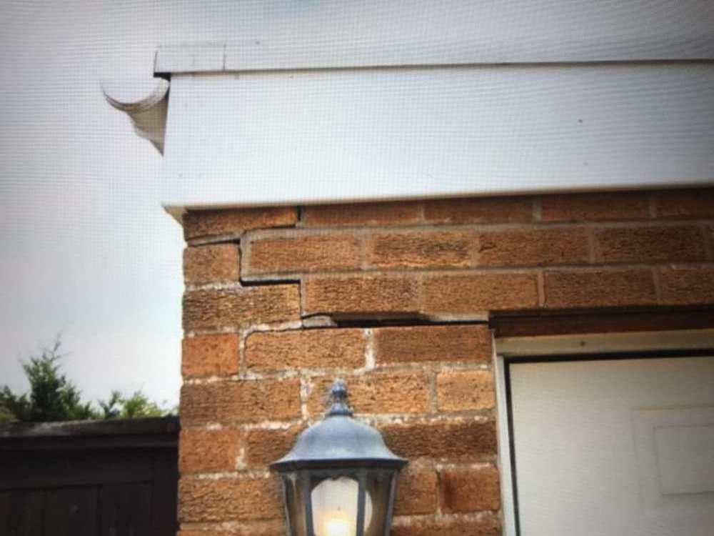
Is that the front moving or the side falling off, or both?! As per @saveasteading comment, it does appear awful.
-
I claim no skills whatsoever with digital pic-wrangling, but try this:
-
Here's the one I 'unearthed'. Big conc. lintel on the inner skin and chicken-wire on the outer, a course above the window-head. The whole estate was built like this.

-
@saveasteading, for clarification, my first post from further up the thread:
-
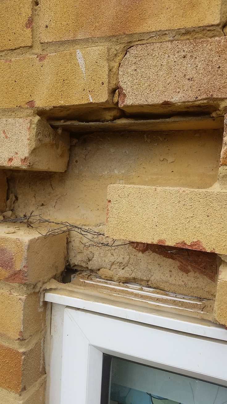
Perhaps I can come in on part of that one. I think I was the one who sowed the 'potentially no lintel' seed. I related a relative's situation where a whole estate of 1960s houses were built without lintels to the external skin, an issue which was not an issue until the sturdy timber windows were replaced with uPVC. I think I have somewhere the pics taken when the builder did 'exploratory' work.
-
Easy? We-e-e-ll, brick removal is not difficult... If it were me I'd prop temporarily (actually probably quite difficult as there appears (again, AFAICS from the pics) to be a tiny reveal, so not much to 'get hold of') and remove a couple of bricks. In reality you may probably be able to remove 2 bricks without propping, but I am not going to recommend that on a house I have never seen, you'll appreciate). If you are better than me at 'reading' boroscope pics you could just drill a hole to look. Edit: Ahah! @iceverge was posting while I typed, and suggesting just that)
-
AFAICS that pic is upside down (the white moulding at the bottom appears to protrude, and the earlier pics show no top drip detail, so I think it's maybe the cill, upside-down), so maybe some of the cracks are down towards the ground (re @Nickfromwales' point). Nevertheless, if we 'park' any cracks below the window for now, can I raise a further possibility? That it is not so much a problem with the lintel, but that *there may not be a lintel*. I had this problem with a relative's house, and it was the same for (I believe) many (tens of?) thousands of 1960's and possibly '70's and '80's houses. In my relative's case the house was built with reasonably stout timber windows, the top rail of which acted as a lintel. That situation pertained perfectly until the timber windows were replaced with uPVC (and at that time many uPVC windows did not have much, if any, steel reinforcement). Then the step-crack appeared, slowly, over a number of years. On sale of the house the issue was raised and invasive work carried out to prove the 'diagnosis': no lintel on the outer skin, and no, the inner-skin lintel did not cross the cavity and 'pick up' the back edge of the outer skin, as one builder had suggested would be the case. As I type now I can look out of the window to a 1960's or 1970's house with visibly 'drooping' uPVC FF windows. I have been waiting for a number of years (and still am!) for the DGU to 'explode' when finally the weight of the masonry above comes fully onto the glass, not (as I suspect is the case still) onto an air-gap above the glass.
-
Airtightness In Refurbishment and Extensions
Redbeard replied to Adrock's topic in General Construction Issues
Only that I don't understand what 'the blanks' are in Should 'blanks' be 'blocks'? And since you feel that the bubble membrane should be OK for air-tightness are you simply asking how you make the joist ends airtight? If so the best you can do, probably, is to tape them into the membrane, with either a/t tape or the butyl tape which you probably bought from Delta. (Of course you still don't necessarily know what any residual moisture will be doing to the joist ends - if they are behind the membrane - I'm not sure because you say 'on top of the ...?blocks/?blanks'). If I have misunderstood please let me know and explain how I have misunderstood, and I'll comment further. -
Not mine - @nod's, but the cost is per m2, irrespective of the no. of storeys. A smaller extension may have the highest cost/m2. A porch I did once certainly did! The 'mastertradesmen etc.' site seems to be a register (though I don't know how you get on it - didn't look that far). They have a number of plaudits from members on the site. I know nothing of its history or operation, I am afraid. I would value personal recommendations from local people above any number of web-sites, though even then you have to bear in mind that people will 'value' different elements of the service differently.
-
Re 1-3 (dot, dot and dot) above: 1. You and your designer. (In certain circs you may opt to get a Certificate of Lawfulness if you think the PD is too 'open to interpretation' (you say it is, Planners say it isn't!) in your case.) Cannot remember how long it took but the one that I have had to do (before online submissions) took about a tree's-worth of paper! 2. Yes, unless perchance your chosen builder has a preferred architect. This of course has advantages and disadvantages. If the architect is used to communicating with the builder directly and responding to 'dynamic issues' as they arise you could, potentially, find yourself with things you have not strictly agreed, however sensible they are. Even if it's the 'builder's architect' you would engage them. 3. Costs: Sorry, no idea. Others will have.
-
@steveoelliott, if you are in any doubt whatsoever perhaps try, via the contractor, to get another couple of clients who are prepared to talk directly to you about this contractor. May help to put your mind at rest. Is he a Ltd Co.? If so you could do some background research at least about the status of the company.
-
BUS grant: what evidence to qualify ?
Redbeard replied to Post and beam's topic in Air Source Heat Pumps (ASHP)
So sorry that you have had this ****. Did they say it in writing? If so, a written reply confirming that you will not pay sets out your stall. If they did not say it in writing still write to them with a statement confirming your belief that they agreed this on x date and have done/said nothing since to change the parameters. What does their contract say about payment terms and the status of the grant in the 'negotiations'? -
I still have vivid memories of getting my cast-iron bath up our stairs (incl 2 winders) 38 years ago. I was younger then, and had 2 friends who were built like 'masonry toilets' (phrase amended for delicacy). One got underneath 'wearing' the bath like a turtle-shell, and the other one and I (definitely the weakest link) took the ends. I do not recommend this method, and I very much like G&J's idea, which could not have worked for us. The only circs in which a Genie lift might have helped would have been if we had removed the bathroom window - and we hadn't! Why ion earth did we choose a cast-iron bath? Because we had bought our replacement 'suite' from my preferred bathroom supplier, the local scrap dealer. He had plenty of plastic baths, which I wanted as much as a hole in the head,but I wanted a pressed steel one. They did not have pressed steel, but 'we've got this'... From the manual handling point of view, not one of my wisest choices! It's still in situ, though.
-
Make a feature of it with a step-down 'cascade' made of gutter off-cuts screwed to (a board screwed to) the wall, then it won't be 'in your face', but artistic.
-
Airtightness In Refurbishment and Extensions
Redbeard replied to Adrock's topic in General Construction Issues
I like drainage membranes better than I like trying to make tanking slurry work, but they can have their issues. Firstly, before lining-out consider 'closing' the top of the membrane. The training I went on with a supplier didn't suggest this, but I found that the % moisture content of some of my joist ends increased after the installation. External ground level was a little below the bottom of the GF joists, so for some of the area I was able to use primer and butyl tape to 'close the environment' behind the membrane, so that the only route would be down for mainly liquid water, not upward (towards vulnerable timbers) via the open top of the membrane. That's one issue, and another (formerly addressed by at least one system provider) is that failure to provide full vapour control around the full perimeter of the insulation can leads to condensation on the inner face of the membrane behind the insulation. If the wall membrane is taped to the floor membrane (again, as suggested by a number of system providers) there is a risk of a 'pond' that your board floor might sit in. The alternative suggested by the system provider was to run the wall membrane down below the floor membrane so that any moisture on the 'wrong' (inner) side of the membrane can at least escape into the perimeter drainage channels. But this in effect 'legitimises' interstitial condensation which is, at very least, a bit hard to get used to. Air-tightness here can be tricky to achieve. Floor is easy - VCL laid over the insulation - and that can join the foil on PIR or A.N. Other VCL, but a conventional VCL at ceiling level will be a VCL on the wrong ('cold') side of the insulation sandwich for the (GF) room. Installed where? Has the extension got a drainage membrane? Surely not? Can you clarify? Can you provide more detail please - words and drawings? More responses when I have a full understanding of the circumstances. -
extension Construction Method in Old Stone Property Extension + Renovation
Redbeard replied to Lears's topic in Brick & Block
The moment you start doing retrofit a 'bit at a time' the un-done bits arguably become vulnerable. This should not be a cause for panic, but regular observation and risk management are your friend. I have differing U values throughout my house ('Incremental Retrofit', or need for a round Tuit). Not least, if you think about it, filling your loft with the 'approved amount' of quilt insulation will give you 0.16W/m2K. If the rest of the house is uninsulated elemental values could be as high as 5 (metal s/g wins) and fairly widely 1.5 - 1.7 (unfilled 50mm cavity and 225 solid brick respectively). -
Yes, section dwgs wd be great. Could the post perhaps sit on compacfoam at btm and have a further chunk of said compacfoam at the top? If you know what 'look' you want, why not simply have the post made with the necessary 'tangs' to which to mount your cladding/expanded metal/what you will?
-
Converting Section of Front Garden to additional driveway/ parking.
Redbeard replied to Charlotte22's topic in Driveways
Does the fact that you have put 'boundary line' in inverted commas suggest that you have doubt about the boundary? The existence of a 'hard' 'boundary' in the form of the fence makes me wonder if the land under the hedge is classified as 'amenity land' - owned by you but with restrictions on use. Is that your driveway in the front of the picture? -
extension Construction Method in Old Stone Property Extension + Renovation
Redbeard replied to Lears's topic in Brick & Block
'Decent U values' for a new extension may be very different from those for IWI'd solid walls. (All values which follow are W/m2K) I'd be looking at something like 0.12 for a timber frame wall. I got about 0.16 for my extension, about which I felt quite smug when I applied for B. Regs approval (when the target was 0.28), but less so when, within months, the new regs came out, requiring 0.18! So I guess I'd try to enclose/'wrap' the old building with the extension as much as possible. You may be looking at only about 0.5 - 0.6 for those insulated stone walls. For roofs of course you ought to be able to get down to 0.10 or even 0.08 - 0.09W/m2K whether the roof is old or new, but if you have sloping soffits you may be limited in terms of room height, and awkward choices ('unfriendly' insulation and really good ins. value vs 'Friendly' insulation and not-so-good U value) may have to be made. For the extension I'd do timber, just because I build in timber whenever I can. I taught a variation of the Segal Method for about 15 years and am pretty obsessed with it! Above everything it is Ridiculously Good Fun and very empowering.