Jump to content

Temporary heat source for UFH: Willis heaters


oranjeboom

26035 views

After various delays, the time has come to get some heat into the house, and as there have been a few on BH that have gone down the route of Willis, thought I would give it a go as well. Hopefully others will find the blog entry also.


Background:

  • Renovated (3G passiv-rated windows, 120mm EPS EWI, 400mm loft insul, MVHR - not tested air leakiness yet) / extended (175mm SIPs) south facing detached house, East Kent
  • 156sqm of wet UFH in 100mm concrete (with circa 300-375mm EPS insulation)
  • 130L in UFH
  • Wunda 12 port manifold (The heating valve on the manifold operates in the range of 30-70oC)
  • Wunda wired room thermostats for each room (but probably won't use for this temporary setup now)
  • 12Kw eDual for DHW (not to be included as part of Willis setup)
  • 12Kw Sunamp for DHW/UFH (not to be included as part of Willis setup)
  • 3.8Kw PV (potentially have further DIY grid implemented later on)


Not looking to cater for worst case low temps as at these times will just plug in some extra heaters:
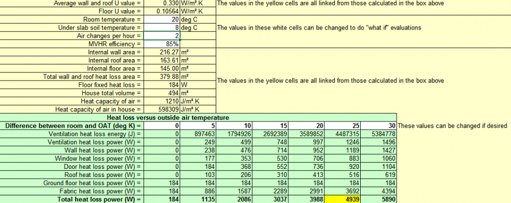
 

image.thumb.png.295847607acdac4392e32785661847d1.png


image.thumb.png.c4678aa7fe5231b1bb4fc06732888055.png


I originally ordered 2x 12Kw heat batteries for DHW and UFH. Total reliance on the PV in summer and then off-peak grid in the winter. An all electric approach initially without ASHP. Not keen to spend £8-10k on an MCS installed heat pump to get back an estimated / possible £8-10k. Installers seem very vague on the RHI returns and if I have read correctly, I will have to be metered in order to qualify in any case (as have not lived in the property previously). Since the house will be far above buildreg stds (but below PH level), I simply won't be using the amount of expected input that the installers calculate - hence I won't be getting back the cost of the ASHP supply and fit install. So most likely won't go down the MCS route, and if I were to install an ASHP, it would be a cheapy from fleabay.


Having excluded using an ASHP, I learnt that Sunamp were testing various units late 2019. But typically with Sunamp, after continued confusion on their part as to what ASHPs they may have tested/not tested/will be testing soon, I've made the decision that I can't want any longer on their input. So for now I will leave the ASHP option until later on and perhaps consider a propane unit (e.g. Vaillant ) when they come online on a non-RHI basis if I can get a decent install cost.


Willis Heater approach

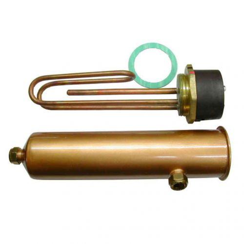
So therefore looking to heat the UFH with 2x 3Kw willis heaters in order to progress with the internal house work. Thought I'd add some info on here as a lot of people like myself aren't familiar what they are. They originated out of Ireland and still much in use over there. They're essentially external immersion coils and instead of sitting inside a tank are simple external electric units - AKA "Willis jacket", "standard sleeved immersion heater"," inline electric heater". Googling should get you something like this:

Willis Immersion Heater | Shell & 3kW Element


Item Weight 1.15 Kg
Product Dimensions

30 x 9 x 9 cm


I have tried to get plumbers interested in rigging this up, but they're either not interested or have told me it's not possible/don;t know what a willis heater is. I've managed to plumb in all the Hep2o in the house, so hopefully this won't be too much of a bodge.


@TerryE has kindly discussed his set up which is pretty impressive with his DS18B20s set into the walls etc. I'm no programmer and my javscript is mainly simple web stuff and wanting to get heat into the place ASAP, I just want a KISS approach for now. Perhaps later I will think about having some of it programmed using Terry's Node Red option which makes for interesting possibilities. Get a feel for Terry's approach here: 


But as I've said, I'm after a bog standard dummies approach to this - seriously KISS:


So rather than wiring up room thermostats to the wiring centre, I will for now simply use the Willis inbuilt thermostat and set that to gradual increasing temps from 10oC up to a max of 25oC. A gradual heat increase seems safer in my mind. My only concern is if the Willis thermostat fails and carries on beyond 25oC - up to max temp. Obviously I will have the manifold mixing/blending valve that should restrict temp flow into the UFH also, but is there a further failsafe to consider?


Dummies layout.

Eventual Sunamp units (for DHW) will be located on left of manifold so having to locate Willis heaters to right  and expansion vessel top right:


1909803810_willissetup2.JPG.ac25b07edcc1b69892d4d33a3c4e984b.JPG

FYI: The immersions need to be turned the other way (so colder water enters the side)


Parts list:

  • 15mm copper pipe. The Willis heaters are 15mm so I presume plumbing them into the manifold with 15mm would be okay?
  • 15mm plastic pipe for cold return should suffice I presume?
  • Bottle vents - automatically release any trapped air (like this one). Do I need any and if so where do I place them?
  • Willis heater (ebay has the cheapest)
  • Expansion vessel - 8litres sufficient for total UFH volume of 130L? (like this one
  • 20A DP switch outlet (for each willis) from a 16A MCB (like this one)  . Probably one for each willis
  • Immersion timer (like this one) to be added possibly when I change over to E7 low tarriff rates


Will get an electrician to wire it all in for me!


Be grateful for comments, suggestions and any answers to above questions!


FYI: I'm no way the first person to install a Willis, so here's a list of other users on BH that have gone the Willis way and will know more than I do:


@dpmiller: photo / details here

@TerryE

@vivienz

@CC45

@chrisb here

@Gav_P - here (Any pics?)


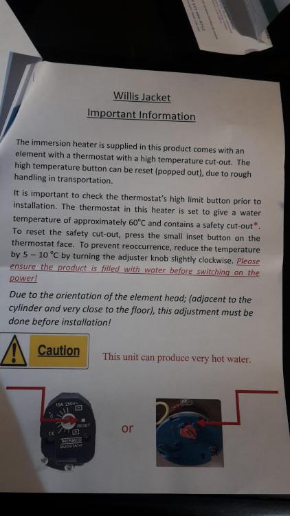
Willis instructions:


schematic


20200117_104153.thumb.jpg.1021a23b20f869bf8516fe2b44605ab9.jpg


  • Like 5

159 Comments


Recommended Comments


15 hours ago, oranjeboom said:

So next question is what cable to bring in from the fuse cupboard to the willis heaters bearing in mind I will have two of them?


This is one for your electrician.  This is 240V stuff and needs to be Part P compliant.  I switch all of my power circuits using Crydom SSRs (sourced from RS Components).  IMO you should be wary about most IoT style switches; whilst many are nominally rated at 16A 220V, you will be driving ~12A for many hours per night.


  These can be driven by 5V TTL outputs, so you can't use RPi GPIOs directly but you can use a level shifter module or something like an The MCP23008 I2C to 8-port GPIO expander which will switch the Crydoms using a 3.3V logic I2C.

Link to comment
17 hours ago, oranjeboom said:

Okay, so no further failsafe is deemed required. Most likely I will be in the house whenever the willis heaters are on as I'll just be dumping heat into the slab gradually via manual on/off means. If it turns out that I don't go down the heat pump route, I'll wire them up via room thermostat.


So next question is what cable to bring in from the fuse cupboard to the willis heaters bearing in mind I will have two of them? They will each have a 20A DP switch outlets.


You could run both off of one breaker at the cu then one "big" cable and split at the heaters. Or give each it's own breaker or rcbo and "small" cable. Personally I'd separate them for complete control.


What length of cable run approx and how will it be installed? Clipped direct, under insulation etc. 

Link to comment
3 hours ago, TerryE said:

but you might find it better to do the main loop in 22mm if it is too noisy. 


It's all in 22mm including large bore flexi's. Only bits that aren't is the section immediately in/out of willis heaters (15/15/22 tees)


3 hours ago, TerryE said:


As to DS18B20s etc., IMO you don't need lots of these


Yes, was not going to use any to start off with. No time to get my head round RPi. It's one for when the house is done. More agro on the domestic front, so no time for 'faffing around'. But I'll be keeping an eye out for your simplification update in due course! I like simples...


Yes, as for the loops I have various lengths. I just went with what Wunda dictated. Longest length is just over 100m and shortest 60m iirc. Will no doubt have to tinker with it when it's up an running. Once I get the bloody electrician round!

Link to comment
1 hour ago, Onoff said:


You could run both off of one breaker at the cu then one "big" cable and split at the heaters. Or give each it's own breaker or rcbo and "small" cable. Personally I'd separate them for complete control.


What length of cable run approx and how will it be installed? Clipped direct, under insulation etc. 

The CU is otherside of hall, so it's and up and over job via the loft above (3m under loft roll) and 4m clipped to wall.


1 hour ago, Onoff said:

You could run both off of one breaker at the cu then one "big" cable and split at the heaters


It's getting a bit tight with cabling space so would prefer this. I'll also have to run in a further cable later on for my two Sunamps also.

Link to comment

For a single cable, nominally 10m long, running through some insulation in the ceiling, you could just about get away with using 4mm² T&E to supply both heaters.  4mm² run like this through ceiling acoustic/thermal insulation would be downrated to 27 A, and 6 kW at 230 VAC is about 26.1 A.  In terms of voltage drop, 4mm² is more than adequate over 10m, though, and would be OK for a run twice as long with no problem.

Link to comment
1 hour ago, Jeremy Harris said:

For a single cable, nominally 10m long, running through some insulation in the ceiling, you could just about get away with using 4mm² T&E to supply both heaters.  4mm² run like this through ceiling acoustic/thermal insulation would be downrated to 27 A, and 6 kW at 230 VAC is about 26.1 A.  In terms of voltage drop, 4mm² is more than adequate over 10m, though, and would be OK for a run twice as long with no problem.


Ref Method 101# in Table 4D5 applies assuming his insulation is thicker than 100mm. Then 4mm is rated at only 22A. Would need to up to a 6mm. 

Link to comment
8 minutes ago, Onoff said:


Ref Method 101# in Table 4D5 applies assuming his insulation is thicker than 100mm. Then 4mm is rated at only 22A. Would need to up to a 6mm. 


Standard for acoustic inter-floor insulation is 100mm though, plus I did make it clear by adding "you could just about get away with" as a qualifier.

Link to comment
1 minute ago, Jeremy Harris said:


Standard for acoustic inter-floor insulation is 100mm though.


Do we know it's that?

Link to comment
4 minutes ago, Onoff said:


Do we know it's that?


It's ground floor, I think, as it's not likely that UFH would be set in concrete on the first floor. 

Link to comment
7 hours ago, TerryE said:


This is one for your electrician.  This is 240V stuff and needs to be Part P compliant.  I switch all of my power circuits using Crydom SSRs (sourced from RS Components).  IMO you should be wary about most IoT style switches; whilst many are nominally rated at 16A 220V, you will be driving ~12A for many hours per night.


  These can be driven by 5V TTL outputs, so you can't use RPi GPIOs directly but you can use a level shifter module or something like an The MCP23008 I2C to 8-port GPIO expander which will switch the Crydoms using a 3.3V logic I2C.

Can anybody translate this language? ?

Link to comment


5 hours ago, Jeremy Harris said:
5 hours ago, Onoff said:


Do we know it's that?


It's ground floor, I think, as it's not likely that UFH would be set in concrete on the first floor. 


7 hours ago, oranjeboom said:

The CU is otherside of hall, so it's and up and over job via the loft above (3m under loft roll) and 4m clipped to wall.


Sorry, probably should have said 'attic'. I've just been up there and I can route it so that the cabling is not covered by 300mm loft roll. It'll only go through the loft roll when it disappears down into the cupboard beneath ceiling level again (where the CU is located).

Link to comment
3 minutes ago, oranjeboom said:


Sorry, probably should have said 'attic'. I've just been up there and I can route it so that the cabling is not covered by 300mm loft roll. It'll only go through the loft roll when it disappears down into the cupboard beneath ceiling level again (where the CU is located).


You can always just increase the cable size to 6mm² to be absolutely safe, although the cable ratings in the blue book are very conservative.   The reality is that the middle runs of cables very rarely suffer from overheating, most of the time it's the terminations at the ends of cables that cause problems. 

Link to comment
1 hour ago, Jeremy Harris said:


You can always just increase the cable size to 6mm² to be absolutely safe, although the cable ratings in the blue book are very conservative.   The reality is that the middle runs of cables very rarely suffer from overheating, most of the time it's the terminations at the ends of cables that cause problems. 


Thanks Jeremy. One 6mm cable servicing both heaters or one cable for each?

Link to comment
Just now, oranjeboom said:


Thanks Jeremy. One 6mm cable servicing both heaters or one cable for each?


One for both is more than big enough, even if buried in insulation.

Link to comment

Thanks Jeremy! Added to my shopping list!


5 hours ago, Pete said:
13 hours ago, TerryE said:


This is one for your electrician.  This is 240V stuff and needs to be Part P compliant.  I switch all of my power circuits using Crydom SSRs (sourced from RS Components).  IMO you should be wary about most IoT style switches; whilst many are nominally rated at 16A 220V, you will be driving ~12A for many hours per night.


  These can be driven by 5V TTL outputs, so you can't use RPi GPIOs directly but you can use a level shifter module or something like an The MCP23008 I2C to 8-port GPIO expander which will switch the Crydoms using a 3.3V logic I2C.

Can anybody translate this language? ?


I dunno but I hope my electrician speaks the same lingo!

Link to comment
6 minutes ago, oranjeboom said:

I dunno but I hope my electrician speaks the same lingo!


@TerryE is referring to the way he's using some homemade smart stuff to both control his heating and to use local weather forecast data to predict how much heat needs to be put into his slab for the following day.  A rough translation:


The "240 V stuff . . . needs to be part P compliant" refers to the fact that all electrical work of this type must be undertaken by a competent person that is registered with one of the Part P accreditation cartels.  Most electricians will be.  The alternative is to get the installation inspected and tested by a building control body, but that may not always be that easy, as in some areas building control don't have anyone competent to undertake third party inspection and test.  The electrical installation will need to have a part P IEC lodged on the database, as it's a legal requirement.  My guess is that your electrician will be able to do this, as most can.


@TerryE uses a microcontroller to switch the Willis heaters, using solid state relays (SSRs) that have an isolated low voltage input and are able to switch a high AC current.  Crydom is just a well-respected manufacturer of these.


IoT refers to "internet of things", and specifically in this case to the many cheaper "smart" switches that are around that may not be able to handle the high continuous load presented by a Willis heater.


"TTL outputs" refers to a 5 V logic level output that can often be used to switch an SSR directly.  The Raspberry Pi General Purpose Input/Outputs (RPi GPIO) operate at 3.3 V, so may not be able to directly control an SSR.


A level shifter is a simple electronic circuit that converts 3.3 V logic levels to 5 V logic levels, usually in both directions.


The MCP23008 is an integrated circuit that can interface with any microcontroller than has an Inter-Integrated Circuit (abbreviated to I²C) serial interface.  It has a higher current drive capability than the GPIO ports on a Raspberry Pi, so can drive an SSR directly.

Link to comment

And there I was thinking a level shifter was a lift!


Yes, I had a chat with Terry a while back with his RPi approach and will look into that more once the house is 'done'.


Part P compliant electrician hopefully turning up next week. I may not be in compliance with the wife otherwise!


Link to comment
2 hours ago, oranjeboom said:


Sorry, probably should have said 'attic'. I've just been up there and I can route it so that the cabling is not covered by 300mm loft roll. It'll only go through the loft roll when it disappears down into the cupboard beneath ceiling level again (where the CU is located).


Over what length will it pass through the "loft roll" and will it be totally surrounded by said thermal insulation? It's important as you may have to apply a derating factor.

Link to comment

It might be worth cabling up the 2 × Willis separately. At the  spring and late autumn bookends you might need less than 21 kWh a night and if so then 7 × 3 kWh is a better profile than 3½ × 6 kWh.


You could probably get away with a couple of 16A rated programmable timers.  If the load is a concern then you could use a couple of 240 V input 240 V × 16A contactors to control the load.  The input to these is in mA, so you've got loads of choices of how to switch these, including a wide range of IoT switches.

Edited by TerryE
Link to comment
25 minutes ago, Onoff said:


Over what length will it pass through the "loft roll" and will it be totally surrounded by said thermal insulation? It's important as you may have to apply a derating factor.


Even applying a very conservative derating factor 6mm² is fine.  The cable could be buried deeply in any non-EPS insulation and not have a slightest issue with over-heating.  4mm² would be OK if only covered with 100mm of insulation, and if not covered with any insulation, but clipped direct, 2.5mm would be just about OK (not that I'd recommend going down to this small a section cable for this sort of application). 


I well remember chatting to a chap from Batt during a break from an LV Directive Working Group meeting years ago, who was literally getting hot under the collar at the way cables were being very conservatively derated by the IET.  There's often a fairly big discrepancy between the ratings that the cable manufacturer's publish and those in the tables in the blue book.  I've never been sure why (and the Batt chap didn't know either).


For example, this is Table 4D5 from Batt:


image.png.8478eca8439187219431434ad91ab956.png


Note that it gives a current carrying capacity of 27 A for 4mm² T&E when covered by more than 100mm of insulation above a plasterboard ceiling.


By contrast, this is Table 4D5 from the current edition of the blue book:


image.png.f463a57bf329007a1fd47e380e8d00c3.png


That gives the current carrying capacity of 4mm² T&E as being only 22 A when covered by more than 100mm of insulation above a plasterboard ceiling.


Given that, in general, MIs should over ride anything else, and as BS7671 isn't law, it's just guidance, there is an argument that supports the view that we should use the manufacturer's data, as they are the ones that have tested and certified their own products.

Link to comment

I'm looking in the OSG, specifically Table F2.


If the cable is totally surrounded by thermal insulation, for example 500mm or more then you must derate by a factor of 0.5. It assumes the insulation has a thermal conductivity greater than 0.04 Wm-1K-1. (Sorry, can't do "to the power" of on this phone). Surrounded for only 50mm of its length it's still a factor of 0.88.


In layman's terms, passing through insulation creates a pinch point/hot spot for the cable.

Link to comment
1 hour ago, Jeremy Harris said:

"TTL outputs" refers to a 5 V logic level output that can often be used to switch an SSR directly.  The Raspberry Pi General Purpose Input/Outputs (RPi GPIO) operate at 3.3 V, so may not be able to directly control an SSR.


For the record: I'm pretty sure that I've driven a 3.3V-friendly SSR, likely Crydom, directly from an AVR running at 3.3V, or an RPi, with no level shifters (I don't own any such thing!)...


Rgds


Damon

Link to comment
1 hour ago, TerryE said:

It might be worth cabling up the 2 × Willis separately


Yes, that was my intention.


1 hour ago, TerryE said:

You could probably get away with a couple of 16A rated programmable timers


Would two of these fit the bill? https://www.cef.co.uk/catalogue/products/4574801-24-hour-7-day-single-channel-1-module-digital-din-rail-timer


1 hour ago, Onoff said:


Over what length will it pass through the "loft roll" and will it be totally surrounded by said thermal insulation? It's important as you may have to apply a derating factor.


A total of 300mm. All clipped against timber.


Link to comment
55 minutes ago, oranjeboom said:

A total of 300mm. All clipped against timber.


That's good. Clipped direct against timber is not considered totally surrounded!

Link to comment
2 hours ago, Onoff said:

I'm looking in the OSG, specifically Table F2.


If the cable is totally surrounded by thermal insulation, for example 500mm or more then you must derate by a factor of 0.5. It assumes the insulation has a thermal conductivity greater than 0.04 Wm-1K-1. (Sorry, can't do "to the power" of on this phone). Surrounded for only 50mm of its length it's still a factor of 0.88.


In layman's terms, passing through insulation creates a pinch point/hot spot for the cable.


It's much more subtle that that, as the manufacturer's higher ratings for a cable in insulation show (and it's not just Batt, other manufacturers have their own specs and ratings). 


There has long been a debate about the way heat is dissipated from cables, and one factor that the rough and ready guidance in the OSG ignores is that most of the heat built up in a short insulated section of cable ends up getting conducted out of the insulated section, as the thermal resistance of the copper is massively lower than the thermal resistance of the insulation sheath and surrounding insulation.  The result is that short sections of cable within insulation don't run anywhere near as warm as might be expected. 


The time factor is also very important, and the ratings assume continuous use at the rated current, whereas in a domestic installation it's rare for any circuit to be taking its rated current for more than a few hours, often a lot less.  It's one reason why, despite it being commonplace for loft insulation to be laid over cables years after they were installed, including cables feeding things like electric showers, it's not that common to find a cable that's overheated in the middle of a run.   Part of that is that the cable can safely operate at a fairly high temperature, usually higher than the stuff connected at either end (the classic being SWA, that is often rated by the manufacturer at 90°C, whereas switchgear etc is rarely rated above 70°C).


It's reasonable that the guidance in the OSG errs on the side of caution, but the OSG is not regulation, or law, it's just rough and ready guidance to how the blue book might be interpreted, in short form, as an easy to reference guide.  If someone chose to use, say, Table 4D5 from Batt, as they were installing Batt cable, then it would be perfectly legal to do so, as Batt have provided a clear specification for their their cable, showing that it complies with the requirements when used within their stated ratings.

Link to comment

Create an account or sign in to comment

You need to be a member in order to leave a comment

Create an account

Sign up for a new account in our community. It's easy!

Register a new account

Sign in

Already have an account? Sign in here.

Sign In Now
×
×
  • Create New...