


SimonD
-
Posts
2215 -
Joined
-
Last visited
-
Days Won
13
Everything posted by SimonD
-
I think it depends on the type of plywood. If it's a decent quality birch ply at 18mm I'd personally have no problems compared to a generic 25mm far eastern hardwood plywood as it will hold the screws. The last time I got some 25mm hardwood stuff, it was terrible, full of voids etc. Just a very non scientific observation was that I left some interior grade 15mm birch plywood outside for over a year and it just went grey. I also left some generic far eastern exterior grade hardwood 18mm outside which delaminated in a few months over winter.
-
Insufficient flow rate for Samsung ashp
SimonD replied to Simon Brooke's topic in Underfloor Heating
That is the pump on the ufh manifold. The pump you have on the primary circuit which is key for flow rates through your heat pump is a Wilo Pico - that's the one we need to know more about as that is the one causing the flow rate error. -
Insufficient flow rate for Samsung ashp
SimonD replied to Simon Brooke's topic in Underfloor Heating
This is quite important. At 15l/m or 0.9m3/h the smallest Pico can only deal with just below 3m head on pump setting 3. Your heat pump at the required 17l/min has a pressure drop of 0.5m head leaving you with a residual of less than 2.5m head on the pump. -
Try https://www.national-broadband.co.uk/ Works for us. Has access to all networks and aerials etc. Router supplied by them.
-
Insufficient flow rate for Samsung ashp
SimonD replied to Simon Brooke's topic in Underfloor Heating
What is the model of the Wilo Pico? -
Insufficient flow rate for Samsung ashp
SimonD replied to Simon Brooke's topic in Underfloor Heating
What is the exact model? Ideally we need to know if you need to increase flow rate or if it's a pressure drop issue. -
This is a problem from my perspective as it's too prescriptive. The English system at least gives provision for multiple ventilation strategies. Natural ventilation really has to be a choice even in very airtight buildings - and despite what some many in the industry say, it with good design works in those building too. Making MVHR mandatory just gives the industry a golden invitation to cream as much as they can out of it.
-
Your approach to the schedule will increase consumption as the boiler needs to run harder when it is turned on at the beginning of each heating cycle. But as long as the system is kept in the condensing zone - return below 54C - at all times, you will see a saving eventually. It's always worth experimenting with different heating approaches, like keeping it on tick over for the whole day with a night time setback and then see what happens, both to your costs and your comfort. Each house behaves differently so needs some testing.
-
Not quite - but we might be talking cross purposes due to different building regulations. I'm referring to England and Wales as I'm not familiar with the Scottish ones. So in England, Part F provides a minimum rate per m2 of floor area, or alternatively a minium rate per number of bedrooms. I'm sure with some properties, depending on the height of rooms, this will be approx 0.5, but in my case it comes out at 0.34 ACH for continuous whole house mechanical ventilation, so the ventilation is going to vary by property. And, of course then Part L says you need to design not to over ventilate. Part of the problem is that people see the 0.5 ACH given in category C of Table 3.8 of the CIBSE Domestic Heating Design Guide, for example, and assume this is a specified/required amount. It isn't, as it says clearly in the guide that houses that have been designed and built with high levels of airtightness require specialised advice to avoid over ventilation. So in these cases, reduced ventilation rates can be used with sufficient justification, usually in my experience to just do the basic calcs using the figures given in the approved documents.
-
We had quotes for Rationel windows. Interestingly the Declaration of Performance gives a specific window size for this best performance value. I was also a bit intrigued that the declaration of performance gives the same value for different types of window and openings at that same size. Our triple glazed windows from a different manufacturer all have a different whole window U-value that was given within the quote and design stages. Whole window value average out at something like 1.03 across the whole house in the end with the detail not differing much from the above image although our frames are a bit more chunky. No, definitely don't do that and rely on it. I've been playing around with using AI for heat loss calcs and system design using several AI models and each of them have got some fundamentals wrong. There's no doubt that Jeremy's heat loss sheet is great value tool, but heat loss calculation methodologies have moved on a bit since that sheet was built. With and MBC passive frame and foundation, whoever is doing the heat loss modelling should be provided with the thermal bridging psi values which are used to input into a full room by room heat loss calculation. Also the heat loss nowadays includes a whole house fabric ventilation loss together with a room ventilation loss which is derived from blower tests because it now considers losses due to wind loads (thus pressure differences across the building). Essentially, the previous way to do heat loss calcs would lump ventilation and infiltration losses into one figure, nowadays these are separated in the calculation, to hopefully reach a more accurate heat loss. It does. As I mention above, the old way of using ACH is heat loss calcs is to lump infiltration and ventilation losses together. So the 0.45 in the spreadsheet must be assumed to be a combination of the 2. The 0.45 for a very airtight house with MVHR I'd suggest could be a bit high with a well detailed build. Mine where I have designed a natural ventilation system (yes @Gus Potter I'm with you on natural ventilation 😉 ) comes out at 0.38 ACH even when using intermittent extract ventilation in bathrooms, for example.
-
Like I have to say repeatedly to my customers, don't focus on the radiator temperature, focus on how warm you are. The controller will increase output when it gets colder just like you're experiencing when it starts up and then modulates down when it's up to temp.
-
Yes, their reputation certainly isn't what it used to be. You should see some of the boilers I get to see that are or have been on a service plan with them and some other large companies. They probably should have separated the new oil boiler with a plate heat exchanger to protect it at original install. But generally the industry is pretty piss poor, in terms of knowledge, ability, care and pride in work. Most seem to be part of a race to the bottom with a disinterest in ongoing CPD. I get regular emails asking me if I'd like to be a subcontractor and they tell me their rates - they're offering to pay me like £400 for a combi swap, and up to £800 for more complex work with system boilers etc. I'd actually schedule 2-3 days for combi jobs (even if you can swap over in as little as a couple of hours) and up to 5 for system boilers to get it done properly, like a full system flush, wiring in new modulating controls and then commissioing the system properly to run a the lowest possible flow temperatures and balance with decent delta T and heat distribution, often requiring a 2nd visit. It would be impossible to do this on the rates being offered where you'd have to join the boiler slinger ranks to stand a chance of survival - that would just be depressing to me. But to get back on topic, for a property with 19 rads I'd be looking at a price of at least £800, probably a bit more, especially when balancing the system post flush as this could realistically take a couple of days in total. Just flushing it out could be done in a few hours, but that isn't in my mind a proper job as the system needs to be tested and working when you leave.
-
Sense check for ASHP & UFH design
SimonD replied to timhowes's topic in Air Source Heat Pumps (ASHP)
I was really keen on Panasonic until I saw this https://www.aircon.panasonic.eu/GB_en/happening/aquarea-hp-and-smart-control-with-tado/ I have developed an allergy to Tado 😉 Joking aside I do plan to add these to my offerings at some point soon. -
Sense check for ASHP & UFH design
SimonD replied to timhowes's topic in Air Source Heat Pumps (ASHP)
I'm not sure that the way the losses are displayed from Jeremy's heat loss sheet is the most user friendly and helpful. Personally, I always derive a W/K heat loss value from the heat loss calc which I then use to understand a what outdoor temperature the heat pump reaches minimum output. For example, if it reaches this at 13C, it may be much less of a problem than if it reaches it at 8C. Some manufacturers, like Nibe provide max and min outputs in charts (not including defrost) for all relevant outdoor temperatures whereas so many just give a figure at a defined outside air temperature and you then have to learn what it really does. By whom? I've tried to extract the info from UK tech to no avail and won't publish some of the opinions I've heard about how to UK market is viewed from some in head office across the pond (only from people who have left to organisation so don't know how biased that is)! -
Sense check for ASHP & UFH design
SimonD replied to timhowes's topic in Air Source Heat Pumps (ASHP)
Best thing to do is step back and look at the heating system as a whole which could allow you to run the system open-loop and allow the heat pump controls to modulate output as opposed to installing a load of control gumpf from the ufh people - a sensible installer would have made this point. Also, if you're thinking about engaging someone to design and install, don't hive off the ufh design to diy and then ask the installer to tack on the heat pump. You need a holistic approach here. -
Sense check for ASHP & UFH design
SimonD replied to timhowes's topic in Air Source Heat Pumps (ASHP)
Who have you gone to? Please feel welcome to dm me if you don't want to publish the list in public - that way I can check if you've been to the sensible ones in your area. I can also point you in the direction of an organisation that can assist you in the design process who are also local but not tied to any particular installer. -
I do think you have to be a bit careful making this assumption based entirely on catalogue figures and also just a couple of manufacturer details. For example, the Grant Aerona 290 is rather different: @ air 7/water 35C 4kW effective power input = 0.82kW cop 4.99 6.5kW effective power input = 1.54kW cop 4.95 9kW effective power input= 1.90kW cop 4.93 12kW effective power input= 2.53kW cop 4.81 15.5kW effective power input= 3.42kW cop 4.62 This, I think is pretty much the inverse of the table you show?
-
On this basis alone, I would go and find another installer who understands heat loss calculations and design. Unless you've made significant changes to your Heat Punk defaults, I'd also caution reliance on those. Since this year, there are 2 ways to complete a heat loss with ventilation losses. 1 is the simplified method that uses a CIBSE design table which is known to over estimate ventilation losses in the majority of cases. 2 is using a detailed method, including blower test results, that is known to reduce calculated ventilation losses significantly. This method takes more time. Then there is an option to deal with thermal bridging. If you are using approved construction details and/or have a SAP calc (which you must have anyway) which also include a bespoke PSI value calculation, you can used reduced thermal bridging values from SAP, for example - not only is this essential from a building perspective, but it improves the accuracy of heat loss estimates too. Modifying all these will help you find a more appropriate heat loss figure. Ignore anyone who tries to tell you what MCS says as that's usually a sign of ignorance. You need someone who understands its nowadays based on BS EN 12831-1 2017, but also be cautious about anyone who just says their tool complies with this standard - ask them to show you their inputs.
-
Detail of IWI on single skin / half brick wall for picky building control
SimonD replied to Bruce's topic in Heat Insulation
I used the European Technical Assessment certification for our woodfibre which was fine by our BC who had never come across the stuff before. I still have yet another stern conversation to have with the building warranty underwriters mind you. -
So to today's questions on our ASHP install.
SimonD replied to MikeSharp01's topic in General Plumbing
Pls see @MikeSharp01 comment below which clearly says it better than I ever could. Thankfully he woke up this morning with a clear head, unlike you and me that get into discussions late at night when we should probably be getting some sleep, or at least I know I should've been! 😁 -
Detail of IWI on single skin / half brick wall for picky building control
SimonD replied to Bruce's topic in Heat Insulation
You used to be able to use LABC approved construction details but since recent updates of Part L, for example, they're no longer in use. Ty Mawr used to have a load of them for their systems. But, I think your BC may need some guidance as there is no requirement that systems must have a BBA cert. The system just needs to be designed by a suitably competent person to show it complies with relevant standards. -
So to today's questions on our ASHP install.
SimonD replied to MikeSharp01's topic in General Plumbing
The waste serving as your D2 can go into the soil stack even if that soil stack has other sanitary appliances attached. You just can't have other sanitary appliances attached to the D2 pipe to the soil stack. Hope that makes sense? -
So to today's questions on our ASHP install.
SimonD replied to MikeSharp01's topic in General Plumbing
I always install these: https://www.unventedcomponentseurope.com/tesla-3-4-expansion-vessel-service-valve-2.html/ Oh, and @MikeSharp01, my usual practise is to have seperate tundish for heating and dhw cylinder as in future it makes life easy to diagnose a problem and where it's coming from.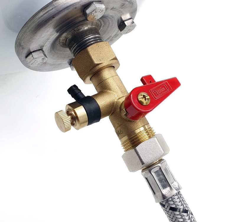
-
At the top of the expansion vessel will be a car tyre type valve which is used to adjust pressure in the vessel.
-
So to today's questions on our ASHP install.
SimonD replied to MikeSharp01's topic in General Plumbing
Your D1 which is pipework up to the tundish must be in copper (metal to be more exact). This should be no more than 600mm in length. You can feed your prv/ t&p and condensate into 32/40/50mm waste no problem, even as a D2 after the tundish as long as the plastic is rated for the temperature. But basically, if you have a waste serving several disharge pipes, this pipe must be at least one size larger that the D2 of the others. Probably better to copy and paste from G3: Where a single common discharge pipe serves more than one system, it should be at least one pipe size larger than the largest individual discharge pipe (D2) to be connected. 3.60 The discharge pipe should not be connected to a soil discharge stack unless it can be demonstrated that the soil discharge stack is capable of safely withstanding temperatures of the water discharged, in which case, it should: a. contain a mechanical seal, not incorporating a water trap, which allows water into the branch pipe without allowing foul air from the drain to be ventilated through the tundish; b. be a separate branch pipe with no sanitary appliances connected to it; c. if plastic pipes are used as branch pipes carrying discharge from a safety device, they should be either polybutalene (PB) or cross- linked polyethylene (PE-X) complying with national standards such as Class S of BS 7291-2:2006 or Class S of BS 7291-3:2006 respectively; and d. be continuously marked with a warning that no sanitary appliances should be connected to the pipe So the question is whether your condensate pipe should even connect to this waste pipe serving the safety valves - probably not if there is risk that pressurised release can return back up into your MVHR. Personally I'd run them separately. The discharge pipe should have a fall of 1:200. If you're running the discharge pipes to the soil stacks it's frowned upon to use a strap boss - use a decent mechanical pipe boss like this: https://www.screwfix.com/p/mcalpine-mechanical-pipe-boss-connector-black-40mm/55722?gclsrc=3p.ds&gad_source=7&gad_campaignid=22478593832 Or this one: https://www.toolstation.com/mcalpine-bossconn-22mm-soil-pipe-boss-connector/p57728 (this one though is a pain to cut the required shape in the soil pipe so I'd recommend the above instead). For connecting 22mm to plastic waste pipes, this works well: https://www.toolstation.com/mcalpine-overflow-universal-compression-plain-tail-reducer/p46778 Out of habit, I tend to put the expansion vessel on the return as I do the filling loop too. So don't forget the filling loop within this list of to-dos. HTH as a start.


