Alan Ambrose
-
Posts
3129 -
Joined
-
Last visited
-
Days Won
13
Everything posted by Alan Ambrose
-
‘Liquid windows’ inspired by squid skin could help buildings save energy “If we had just one layer that focuses on modulating the transmission of near-infrared light – so not even touching the visible part of the spectrum – we find that we could save about 25 per cent annually on heating, cooling and lighting energy over a static baseline,” says Kay. “If we have two layers – infrared and visible – it’s more like 50 per cent. These are very significant savings.”
-
Fixing into plasterboard
Alan Ambrose replied to Temp's topic in General Self Build & DIY Discussion
>>> The issue with quite a lot of fixings is that they don't service the fixing being temporarily removed because the back bit drops down down the cavity. A total PITA IMO. I find those squeeze-grip fixings very effective but you need to work out how to remove them with the minimum amount of damage if you need to. In the case of these fixings, I find that the easiect way is to unscrew then part rescrew in the bolt then give it a bang with a hammer. This punches the whole fixing through into the void -- at least enough to leave a small indent or even a small whole which can be filled, sanded down and painted. What ever you do, don't try to pull them out as this will tear out a big whole in the board. <<< Yeah I agree with both those thoughts. All of these fixings are made with dodgy thin stuff unfortunately (presumably not good quality steel) - perhaps they need to be a bit like that so they can be squeezed by hand. This means that they need to be treated with some care during installation. After they're installed they're nicely strong. I found 'Fischer HM-S cavity fixings' to be the best. -
Fixing into plasterboard
Alan Ambrose replied to Temp's topic in General Self Build & DIY Discussion
+1 for the anchors that Temp suggested. Treat v gently until they’ve pulled in, otherwise they can fail in all sorts of ways. Fischer brand are best in my experience. -
decent metal drill bit recommendations?
Alan Ambrose replied to markharro's topic in Tools & Equipment
Slow speed so you don’t burn it up. The bigger the hole, the slower the rpm - it’s the surface speed that’s key. +1 for coolant/cutting fluid. Also clear the chips if they’re building up. Rotabroach / annular cutter if they’re not tiny holes. -
The science behind sewage treatment plants
Alan Ambrose replied to Crunchynut's topic in Waste & Sewerage
>>> The science behind sewage treatment plants I think you've opened up a whole new can of ......... worms there. -
>>> I was planning to put in some tubes but didn't get round to it That's what bag-ass SDS drills and masonry and diamond core drill bits are for. Even better if you don't mangle the UFH or DPC in the process.
-
Yeah the EPC guys, who are often crazy cheap, just put 'assumed' if they can't be bothered or simply can't find out. They often won't even bother to ask the owner whether they know or have any docs. Even the floor area is usually way out and that should be easy. I leaned on the guy who re-did the EPC for my mother's flat and told him he would need to explain to me why in detail, since there had been no change to the building, if he didn't come up with the same EPC rating (B) than the one that had just run out. Actually, he did extra work to locate the info as he was a good guy. My EPC is E right now for a building that had a frame up re-build in 2017. How is that even possible given BC regs? Well: Walls (assumed), Floor (assumed). Yeah, that'll do it.
-
Well it would be a great help in 'protecting the building fabric of the nation' if this information was made public where held by BC. I've just found that, in our barn conversion 1850/2017, that there's a non-insulated void of about 15cm under our plasterboard. WTF. I have an old doc from the structural guy involved in the 2017 conversion that was in the legal pack and contains some wall & roof buildup. But it would be more than helpful to know the stack up in more detail. I've been struck over the last few years that we normally buy houses in the UK largely without having the faintest clue how they were put together. Seems to me we're buying the look and feel of a house rather than an actual structure.
-
That's it really. I want to see the as-built wall / roof / foundation detail if I can. Presumably they must keep copies.
-
p.s. this closes today
-
For the people who have got their BC to accept alternative calculation methods - is this LPA BC or third-party BC, and if so, which company?
-
Wow, fantastic result! Now I just have to convince East Suffolk LPA to take the same approach... Also v. useful to know that BC have some flexibility and don't need to adhere slavishly to the 'rules'.
-
>>> The iteration of even the Simplified model could end up being expensive. Do that one your self and you can play as much as you like. A one-page spreadsheet. >>> I'm waiting to find out of the LPA will accept PHPP for Part O. That would be a major win.
-
Why Zoning of heating is Bad Practice
Alan Ambrose replied to Dave Jones's topic in Underfloor Heating
Yeah, the other half likes v cold bedrooms - windows open even in the winter - and I like warm bathrooms. Also, I think there's something to feeling some temperature variation rather than living in a hermetically sealed box. Alan -
Your thoughts on this design?
Alan Ambrose replied to Alan Ambrose's topic in New House & Self Build Design
Yeah hard to tell with all those sticks . There are tie beams all through at wall plate height and 1st floor level. There are meant to be full height posts in the gables but not shown there yet - but good point about the intermediate walls. Re the collars, they could be a bit lower, ceiling height on the 1st floor is 2.7m right now. The truss is there in the design atm mostly, of course, to stop door/window openings from being in dumb/impossible places. Ahhhhh - I've just realised who you are - and I was planning to get in touch! Our existing little barn is in Witnesham. I'll ping you my details. -
Cladding and how to Finish Bottom
Alan Ambrose replied to GrantMcscott's topic in General Construction Issues
Ah, I see, whoever built has not followed the design - as the membrane shown in the design is flush with the outside of the bricks - whereas in the actual build picture the membrane is flush with the inner face of the brick. (Edit ... actually if there's a cavity there as well, not clear in the picture, then it's the width of the cavity back as well.) The design then shows two layers of 40mm battens, one horizontal, one vertical and then the cladding - so about 95mm from the membrane (and intended to be 95mm from the outside of the bricks). That way rain runoff from the cladding falls straight into the french drain - which is quite important. Edit: I think you have to decide whether you're building to the detailed design you've show above in the drawing, or your own design. Doing your own design is fine, if you're happy to take the risk - most people are not, but I suggest that you want to get the ventilation, membrane, drainage and insulation detail right as well as the aesthetics. -
Yeah, I think it's a good example of a out-of-the-ordinary situation that HMRC felt they should challenge. Then a professional getting a good result (and earning their fees) by knowing the rules and being prepared to challenge. Congrats and thanks for the commendation.
-
Cladding and how to Finish Bottom
Alan Ambrose replied to GrantMcscott's topic in General Construction Issues
Maybe another fibre cement board? -
Cladding and how to Finish Bottom
Alan Ambrose replied to GrantMcscott's topic in General Construction Issues
The diagram suggests 1/2 brick above ground level, covered by 50mm-ish insulation then an unspecified protective layer 15-18mm, then a french drain. Possible to ask the designer what they intended for the unspecified layer? -
Cladding and how to Finish Bottom
Alan Ambrose replied to GrantMcscott's topic in General Construction Issues
Is there a better diagram so we can see what's going on rather than make it a 20 questions thing? ATM your bricks appear to be finishing two bricks above ground level, which looks fairly sensible? Are you planning to raise the ground level then to cover those bricks? -
Cladding and how to Finish Bottom
Alan Ambrose replied to GrantMcscott's topic in General Construction Issues
Err, cladding finishes below top of brick/concrete wall so residual rain can drain off cladding onto ground / gap left open at bottom between cladding and brick/concrete for ventilation / gap bridged with a vermin/bug preventing mesh? -
The cost sounds not unreasonable to me. Simplified Method is simple-ish (say, an hour or so) once you have the window / door / room sizes. Do your quotes allow for iterations - it's likely that if you're over the limits, that you'll want to do a bunch of what-if calcs? So, if that's cost per iteration not so useful, if it's cost to get to a workable detail design, that's much better. Does 'dynamic thermal modelling' handle solar gain and shading? Who's the supplier, a bunch of us would be interested I'm sure? I think the various simulation packages (as opposed to 'Simple Method') may come up with quite different results, so it's possible some people will want to do 'simulation shopping' to get the most favourable results.
-
Your thoughts on this design?
Alan Ambrose replied to Alan Ambrose's topic in New House & Self Build Design
Yeah, I kind of agree. FYI here's the overall frame for planning application purposes i.e. a structure to hang the look and feel on. That is, before detail frame design.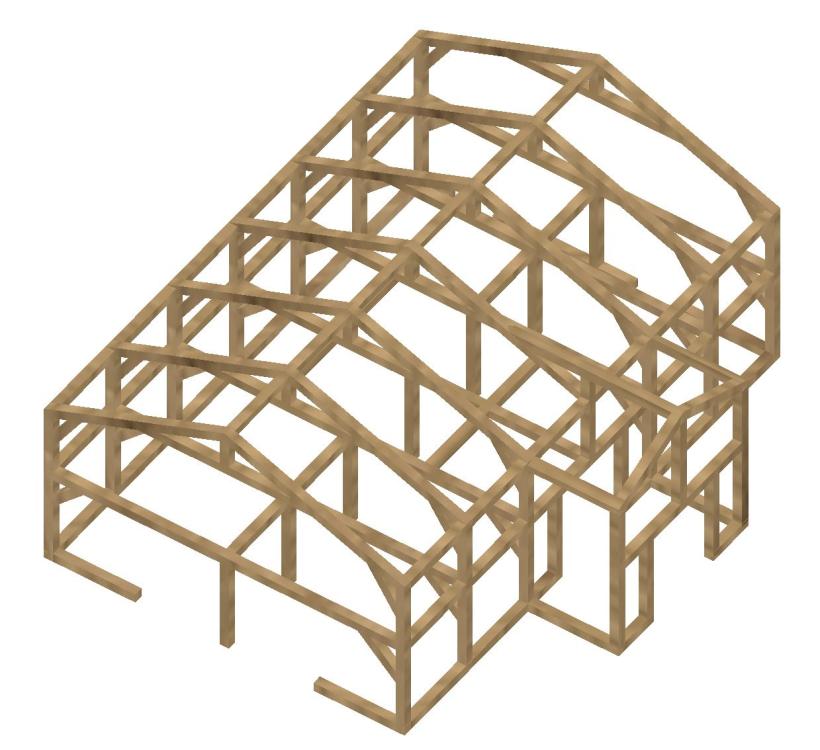
-
@cheekmonkey - is your 'failure' pre or post-planning sign-off? And, I agree that Part O simple method is nonsense as e.g. it doesn't 'allow' mitigation. Clearly, mitigation options in a London flat are generally limited (that 'use case' seems to be the whole driver for Part O), but for suburban or rural houses it's no problem at all. Even after-the-fact once the thing is built. There now seems to be 4 or more ways of calculating solar gain (Part O simple / TM39 / PHPP / Part L Criterion 3 etc) and I wonder whether anyone has done a comparison?
-
Your thoughts on this design?
Alan Ambrose replied to Alan Ambrose's topic in New House & Self Build Design
>>> ensuring the design accounts for the 'rule set' of oak framing before you submit for planning >>> A general rule of thumb is to keep any clear span less than 5m. Yeah, I think I've got that. It has 7 regularly spaced trusses 2.4m apart and the max unsupported span is 5m. Our existing barn conversion has 6 trusses, 6m open span, the spacing varies unevenly between 2-3m - probably depending what oak sticks they had around at the time. Some complaints in this thread about the regularity of the windows might not have appreciated the oak frame restrictions, compared to say block. >>> however the issue is structural characteristics when it comes to engineering calculations. It's hard enough finding an engineer that will provide reasonable calcs for oak, let alone other species. Yeah, I don't understand why though. Fusion will do the structural calcs for you fine. Maybe structural guys are bothered by the potential variation in wood compared to say, steel and/or how the framing joints should be modelled and/or anisotropy/grain. I have not run the Fusion calcs part yet but I'm going to guess that we'll be well over 3x safety margin with 25x25cm beams. There won't have been anyone doing 'structural calcs' at the time of building our current barn (c1850), and it's been there for 150 years . I will, of course, have to run some official calcs around the BC loop though.