


iSelfBuild
-
Posts
339 -
Joined
-
Last visited
Everything posted by iSelfBuild
-
 One solution is build as a mobile home which can be 0% rated if BS3632.
- 19 replies
-
- 1
-

-
- vat refund
- vat exempt
- (and 2 more)
-
Thanks! Yes he did inspect it all and said it was in very good condition, weight off my mind. Selling houses is bloody stressful.
-
In 2017 I had a log burner fitted in an open fire place. All work was done by a HETAS engineer and the accompanying report filed. I note at the time he persuaded us not to have a flu liner or system installed so that section is left blank. We are just selling our house and I'm now anxious that maybe this wasn't installed compliantly after a comment from the estate agent asking if there was a liner installed ?
-
I design and build log cabins in accordance with the caravan act. If you are planning to put it through as a caravan then you will have to prove it complies and that it's capable of being moved. If your using a lightweight wall system, then the very simplest way will be to build off a rolling chassis - a 6 x 17m one will costs about £2,500.00 delivered. Good luck if your local council get interested and start asking questions. I had structural calculations commissioned proving my very heavy cabins can be lifted by a ”MIStructE” (this was requested) engineer and had to put together a comprehensive method statement demonstrating how it complies and meets the caravan act and I suggest you should get this accepted by your local planning and building control to prevent future complications. BS3632 is not that hard to achieve. In terms of VAT form a LTD company, voluntarily register for VAT - claim VAT back on all materials and zero rate the supply of the caravan (not groundworks, removable goods etc) - not sure HMRC will like people openly doing this and if you are not achieving BS3632 in every way it should not be 0% rated so it could get you in bother.
-
Wood burning stove in timber extension
iSelfBuild replied to DC5's topic in Stoves, Fires & Fireplaces
As Dave says get a convection stove and it resolves this distance issue, use these in my cabins. Contura has some nice modern convection stoves -
The window head board looks like it sits directly underneath the cladding, when you have driving wind and rain won't it run down the cladding above and track back into the property or is it angled? It's not uncommon for the larch to split and crack when drying out. We screwed all of our cladding so we can remove each piece. Eventually going to replace a few boards that have bad splits but there is not many. I did the window head like this:
-
Rainwater Soakaway Design???
iSelfBuild replied to iSelfBuild's topic in Rainwater, Guttering & SuDS
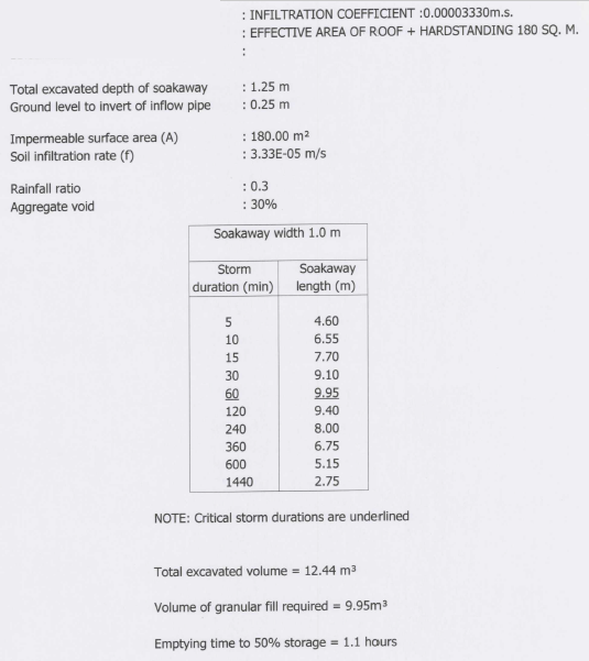
That makes 100% logic ? But how do you calculate the volume or should I say displacement of gravel? The chap at the top (screen print) had Aggregate void at 30%... So 1.32 m3 x 3.33333* = 4.39 m3 I would say that is a very suitable sized soakaway??? -
Rainwater Soakaway Design???
iSelfBuild replied to iSelfBuild's topic in Rainwater, Guttering & SuDS
Thank you, I'm still a bit confused. This calculation seems to suggest 1.32m3 is big enough but it doesn't say if this is for crate systems where there is a big void or if it's for granular rock infilled soakaways. -
Rainwater Soakaway Design???
iSelfBuild replied to iSelfBuild's topic in Rainwater, Guttering & SuDS
Any ideas how I take the m3 area and convert that into a real life sized drainage pit? I can't get my head round why the one I posted initially was specified at 1m x 10m -
Rainwater Soakaway Design???
iSelfBuild replied to iSelfBuild's topic in Rainwater, Guttering & SuDS
Can anyone confirm I am working out the area correctly? 1m x 3m - 50% depth would be 0.5m, the base is excluded so it is 0.5 x 1+1+3+3 = 4m2 f = (1/VP) / 1000 or 0.00003367 = (1/29.7) / 1000 For 100m2 area to be drained: The soakaways may be sized using the following simplified formulae derived from BRE Digest 365: (A x 0.0145) – (a x f x 900) = S (100m2 x 0.0145) - (4 x 0.00003367 x 900) = 1.328m3 So how do I then take this 1.328m3 area and size the soak away considering it will be filled with clean rock. -
Rainwater Soakaway Design???
iSelfBuild replied to iSelfBuild's topic in Rainwater, Guttering & SuDS
Thanks. So a - is the internal surface area of the soakaway to 50% effective depth, excluding the base in m2. So say 1m x 3m is... 0.5 x 1+1+3+3. So 4m2? Assuming the top isn't considered as well as the base of the pit. -
Rainwater Soakaway Design???
iSelfBuild replied to iSelfBuild's topic in Rainwater, Guttering & SuDS
Yes there is a long winded way for f value, then there is thankfully the method of doing a VP value and converting it. I just don't get the whole a = assumed bit as that completely changes the final outcome so is open to manipulation? -
Rainwater Soakaway Design???
iSelfBuild replied to iSelfBuild's topic in Rainwater, Guttering & SuDS
Thanks is this the simplified formula? I'm assuming I calculate VP the same way as in drainage fields? The soakaways may be sized using the following simplified formulae derived from BRE Digest 365: (A x 0.0145) – (a x f x 900) = S Where - A is the area to be drained in m2. a - is the internal surface area of the soakaway to 50% effective depth, excluding the base in m2. This has to be assumed for initial calculation purposes. f - is the soil infiltration rate, in m/s, determined in accordance with clause 3.9.1. This calculation produces Vp in secs/mm [conversion = (1/Vp) /1000]. S - is the required storage in m3. I know the VP was 29.7 for the drainage field, so I do a test like that and convert it into a f value? = (1/Vp) /1000]. a is the internal surface area of the soak away? I'm a bit confused by it being assumed? -
I'm a little confused on this one. I have done a fair few percolation tests in the past in order to design drainage fields for treatment plants. Area = Population x Percolation Value (Time from 75% down to 25%) X 0.2 (secondary treatment) / A = P x Vp x 0.2 Calculating the VP is a dead easy process. I have attached the results of one of my rainwater soakaways on a site, I never did the calculations for this or the soil infiltration test for them. How is the soil infiltration (f) derived/performed? Once I have the figure how do I replicate this sheet I have too?

-
I quite liked living in a touring caravan for 16 months haha. The saving grace was ripping out the gas fire and fitting a micro log burner.
-
I'm interested to see them. Especially the timber ring beam construction. What dimensions where the outer timber for that?
-
To be honest John, I don't think anyone up there knows what's going on and that includes SW and me! The supply comes from the farm so that could be why it's 90mm? No the Hydrants at the lower part are directly off the 90mm. Aditional hydrants at the top of the site... I'm guessing that's coming off a 50mm from the header tank.
-
Nope. 90mm comes into the site, no meters what so ever. This stops in 90mm as soon as it comes into the site. It then comes off in 32mm supply pipes (from memory) One comes off into a break tank for the pumped supply to the header, one just comes off for the mains supply to the header - which it also tees off at my parents plot for their supply. Absolutely no meters on any of that. Not sure what the pressure is rated at on the header tank system, I have stayed in my neighbours chalet once and it was not terrible but not high pressured for sure. My parents 700 litre tank and pump - we can set that all the way up to 9 bar pressure so works pretty great in my opinion. I'm likely going to fit a dab e sybox mini in my log cabin if the pressure is not great when I test it. (My log cabin is served off the header tank system) there is no issue with flow and the pressure seems OK, but haven't tested it with a gauge yet. The only place SW are putting meters are where it feeds into each plot boundary.
-
Scottish Water. There is 7 chalets on the pumped header scheme. Then 1 chalet (my parents on just the mains flow pipework) So 300mm from the 90mm mains, all the way up to the header tank. 25m head. Then each plot is at varied distance from the header tank with at least 10m of head of pressure from the header tank.
-
There is fire hydrants at the bottom branching off the 90mm mains. Then there is fire hydrants branching off the downward supply pipe off the header tank opposite our plots. Never liked the whole set up to be honest and I had no involvement in it's design. It would be about 300m, but it's pointless to do anything else now. It works well both on the pumped header tank system and on our mains flow (sporadic flow and low pressure - but then held in tank in the lodge and pressurised system)
-
I think it's about 300m from the 90mm Scotish water mains to our sites - there is no meter down there though. They are just metering it at each property where they take it out of the header tank.
-
90mm mains coming to the site. This is where they guarantee 1 bar pressure. There is a few fire hydrants which branch off this 90mm mains. Then the header tank is fed by a 32mm mains pressure pipe and then a 32mm pumped pipe (in back up) The chalets rely on gravity yep, it's a fair old instant drop from the upper site to the lower. I think it comes down from the header tank in 50mm all the way down and branches off to each challet plot in 32mm.
-
They only guarantee it at the bottom of the site where the 90mm terminates. We are about 300m away from this on the private supply pipe.
-
Some times during the day the flow can be zero, in fact had a few rare days when it's been nothing. So the idea of the big scheme is that the holding tank (at the very top of the site) is filled by mains pressure very slowly by a mains flow pipe when there is pressure and flow through the mains pipe. If it ever get's near empty then the pumps kick in and feeds via a separate pipe. They very rarely kick in to be honest. The header tank then pressures the flow down. God knows why it was designed like this. The 90mm is only where it comes into the land from the neighbouring farm. It's teed off in 50mm I think straight away. We never liked the idea of it all that's why we never bought into the scheme and put in our own holding tank and pressure system in our lodge. It works great. When I bought my plot next door which is a rental unit I bought a plot which was on the scheme. So I now have all the hassle of ongoing maintenance, one of the pumps has had to be replaced already. There not cheap!
-
We have a water pumping solution on our site in Dumfries & Galloway which serves 7 dwellings. It is all metered for water usage by Scottish Water at each property - is that uncommon? We never bought into the scheme... we just fitted one of these as we had enough flow over 24 hours, just bugger all pressure - https://www.anglianpumping.com/product/mains-pressure-boosting-systems/dab-e-sytank-and-e-sybox-pump?gclid=Cj0KCQjwgJv4BRCrARIsAB17JI4oS9PBBmPmdaWTDATjh_k3Rt0JeX33jOCaen7mXSL0o2UM9B_TfKYaApQUEALw_wcB Here is some old information from 2012 on the solution implemented for the other sites: 1) 2700(?) litre header tank at upper end of site. Underground tank used, probably placed on surface and buried. 2) 32mm pipe connecting lower 90mm main water pipe to header tank. Ball cock connection to header tank. 3) Existing site water pipework separated from the lower, incoming, 90mm water main. 4) Dedicated electrical supply, with separate meter, taken to lower water main by buried armoured cable. 5) Pump(s) at lower 90mm main to feed header via 32mm pipe, connected at the lower 90mm mains pipe separately from the 32mm pipe described in 2) . Ball cock at header. Pumps installed in insulated and frost proofed cabinet. Pumps to have pressure sensitive switches and to be fitted with break tanks and timers. Above ground pipes in pump area to be insulated. 6) Pumps on timers to provide water to the header tank. Possibly running several times during a 24 hour period. 7) Header tank connected to existing 90mm site pipe by 50(?)mm pipe. 8 ) Pipe flushing valves fitted. 9) Surface water tank to replace hydrants. 10) Water purity tests – initially and yearly. 11) Capital, running and any maintenance costs shared by users. The header tank is small enough to be emptied and refilled on a regular basis, avoiding stagnant water. Site Description:- Existing 90mm mains water pipe at the lower end of the site. Water pressure at this 90mm main has become varied, sometimes providing pressure to supply the whole site, sometimes not. The length of the site over which a water supply is required is 350 metres. This 350 metres starts at the lower end of the site (the 90mm mains pipe position) and rises approx 25 metres. POSSIBLE SOLUTION. To cater for the unpredictable pressure reductions :- A header tank (2700 litre?)to be placed at the end of the 350 metre supply run described above. This header to be connected to the 90mm lower mains pipe so that the header tank fills under mains pressure when it is available. The header tank to be filled several times a day if necessary to avoid stagnant water. This header tank to be connected to pressurise the existing site pipe network. The existing site pipe network to be separated from the incoming 90mm lower mains supply When the mains pressure is too low to fill the header, then a pumped system to be used to fill the header tank. The pumped system could be as follows: 2 pumps (to have a backup if necessary); break tanks to the pumps to comply with water regulations; pressure sensitive pump controls so that when the header tank was full the pump would stop; a timer to each pump so that the pumps could run alternately for a number of times a day (if the header tank was full then the pressure sensitive switch would stop the pump irrespective of the timer); insulated pumps and associated pipework (shed or cabinet); a separately metered electricity supply to the pumps.