Tony L
-
Posts
385 -
Joined
-
Last visited
Everything posted by Tony L
-
Sorry, @Andehh, I forgot to respond to this. I've thought about trying to get rid of some of the mortar that's bridging the DPC with an angle grinder, but I'm conscious that if I accidentally cut a small channel into the trench blocks right at the edge of the beams, this will be a point from which a stress fracture could start, & I really don't want that. Chiselling might also give rise to stress fractures. Even if care had been taken with the installation of the 100mm wide DPC, & there were no mortar bridges, I would still not be happy that the DPC would provide maybe 1mm separation between the beams & the damp trench blocks. The k-Kaps look a lot more chunky. Any input on my idea of jacking up the beam ends & putting K-Kaps on them would be most welcome. Or, if there's a better affordable solution, I'm keen to hear about it, please.
-
-
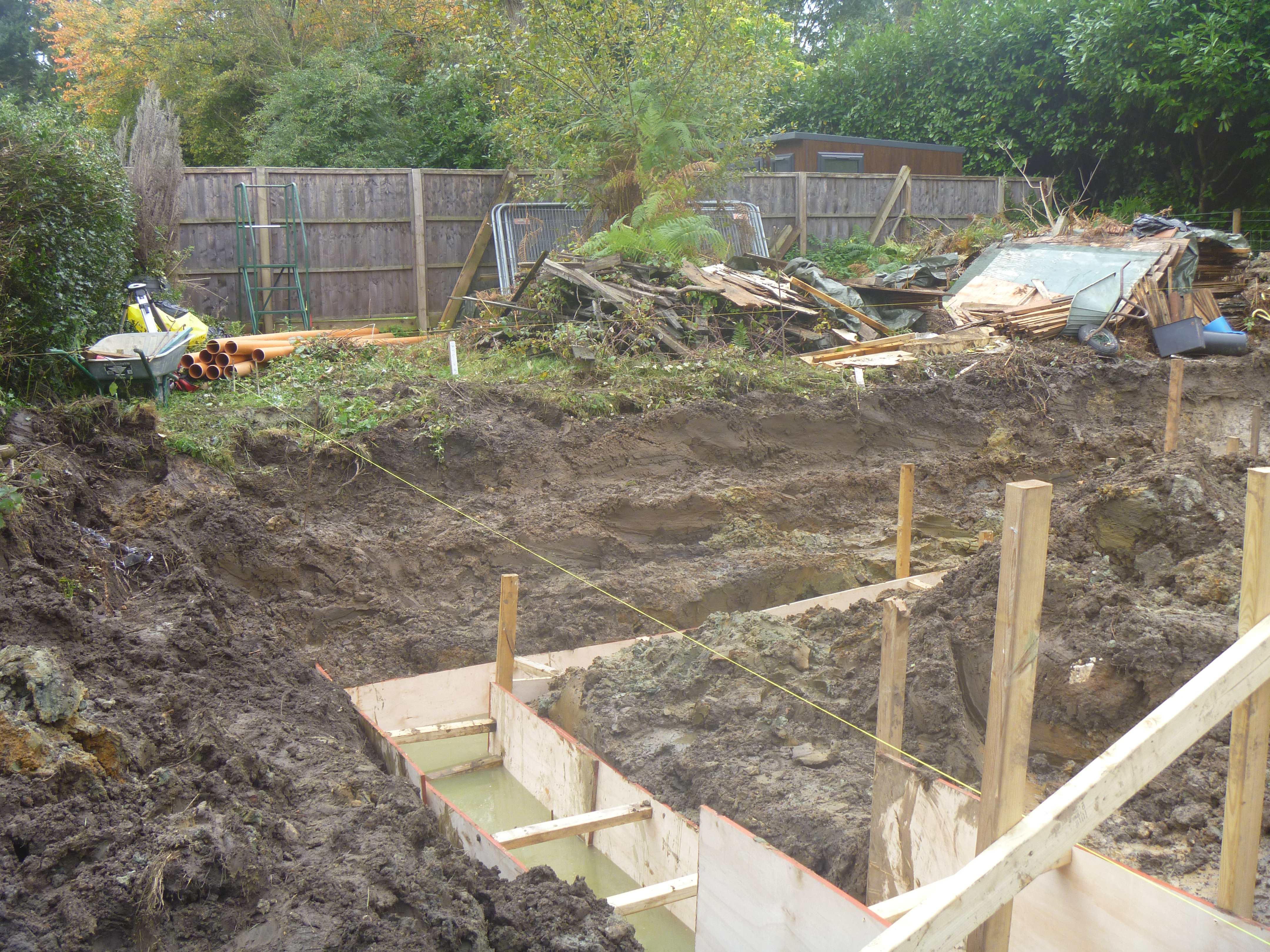
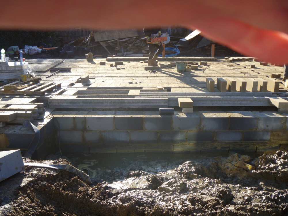
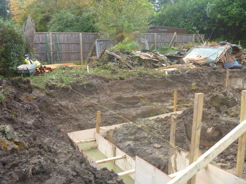
Thanks @Mr Punter. According to the builder, the building inspector has seen everything & says it’s all good. The builder has written to me to confirm this. You’ve got me thinking now, I should explain to BCO, it has become clear the builder has been lying to me. I should ask BCO: could he please confirm everything that’s been built so far is building regulations compliant? I’m going to be overseeing remedial works to improve the ventilation to the void beneath the B&B. I don’t care what BCO says – I want to build to a good standard, rather than the low standard at which BCO will say things are acceptable to them. Regarding the ground level: the planners were very awkward with regard to the ridge height, so we’re stuck with the floor so close to ground level. It’s not a compromise I’m happy with, but I didn’t want to spend a ton of money just to end up with a bungalow or a house with horribly low ceilings. The first trenches (1m) deep were dug neatly & were shuttered. When BCO came & said he now wanted to see 2m trenches, we ended up with wide V shaped trenches, due to the wet ground & cave in risk. A lot of backfilling was done after the trench blocks were laid, so the this may account for the high ground level. Also, there’s 150-200mm of crushed concrete surrounding the building (1.5m wide apron) for the scaffolding to go on, so perhaps this can be scraped back at some future date.
-
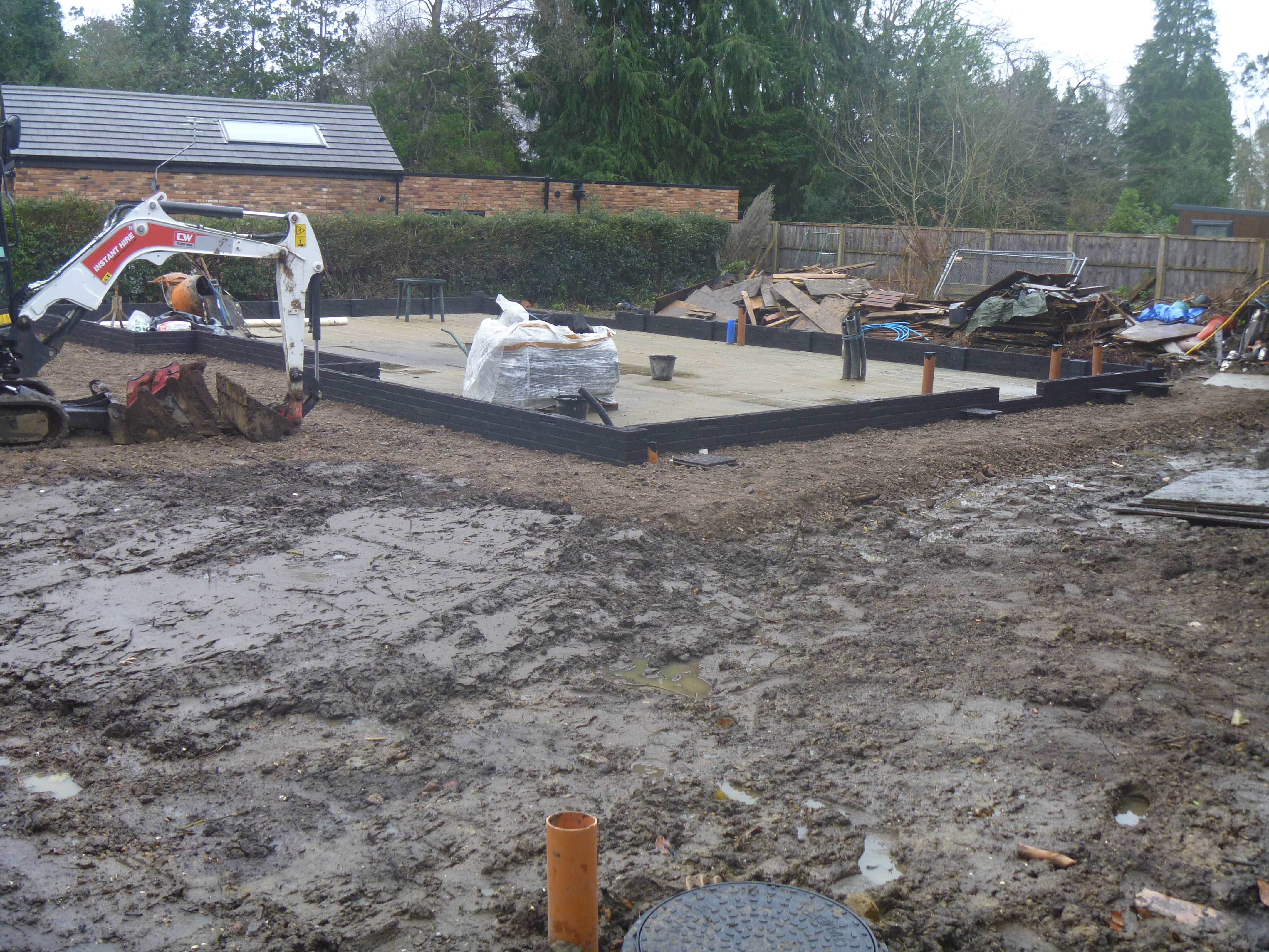
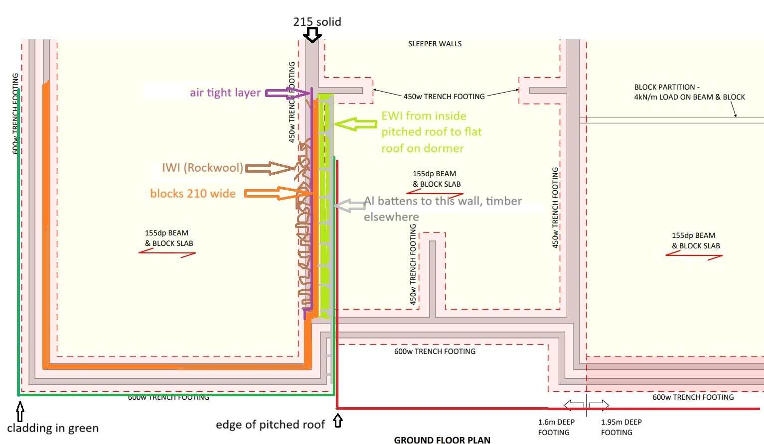
Actually, this doesn't show how it look now. This is before the last three or four courses were added.
-
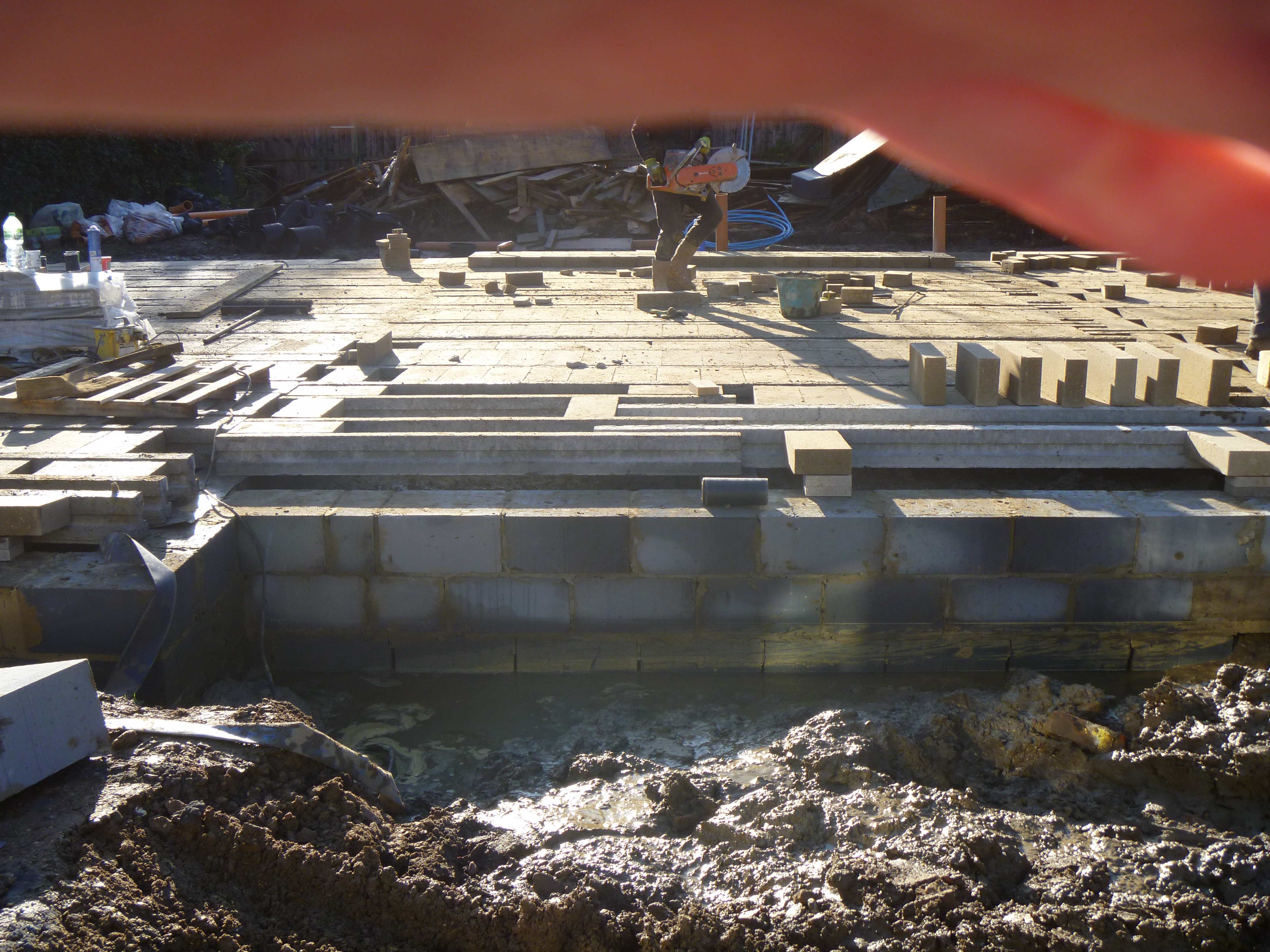
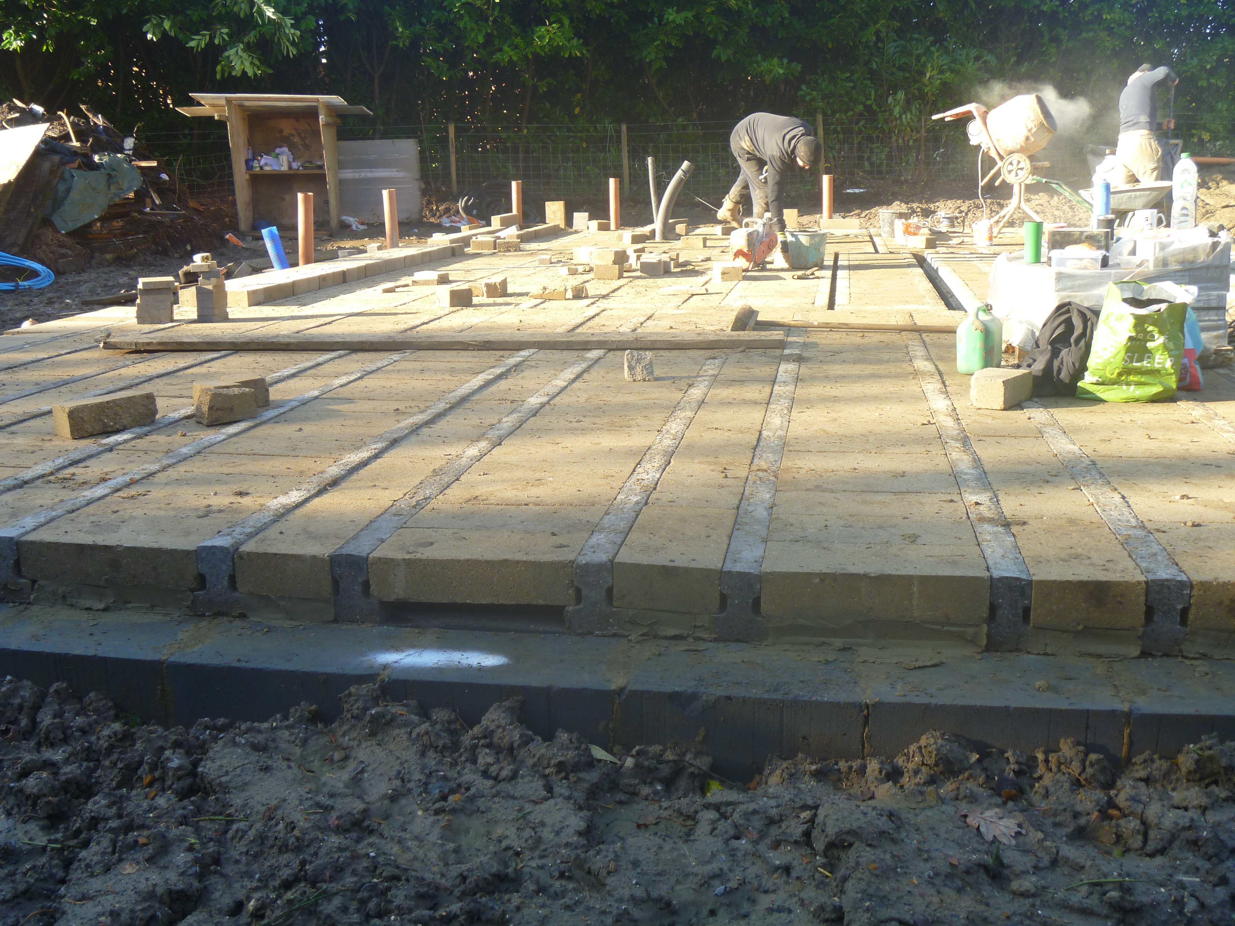
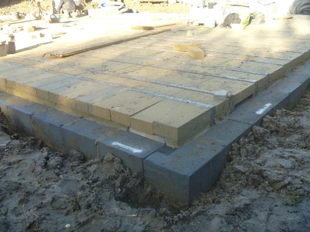
Yes, the cowboy builder started building up the outer leaf. It's very bad (see thread linked above, if you're interested). I may end up knocking the outer leaf down & starting again, or I may just take out the air bricks, or I may re-do the air bricks & the whole of the start of the outer leaf across the facade, because the black bricks are already looking terrible, due to efflorescence. Those black bricks were quite expensive & the mortar is quite strong, so it would be a job to clean them up & re-use them. These pictures show how things look on site right now.

-
No - there are unpaid invoices totalling £10,800. Let's focus on construction advice on this thread, please, & I'll update my other thread when I have more to report on the dispute/litigation. This one...
-
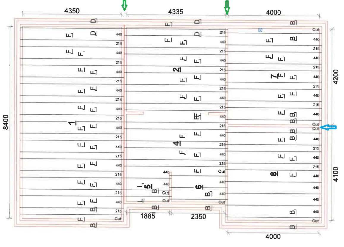
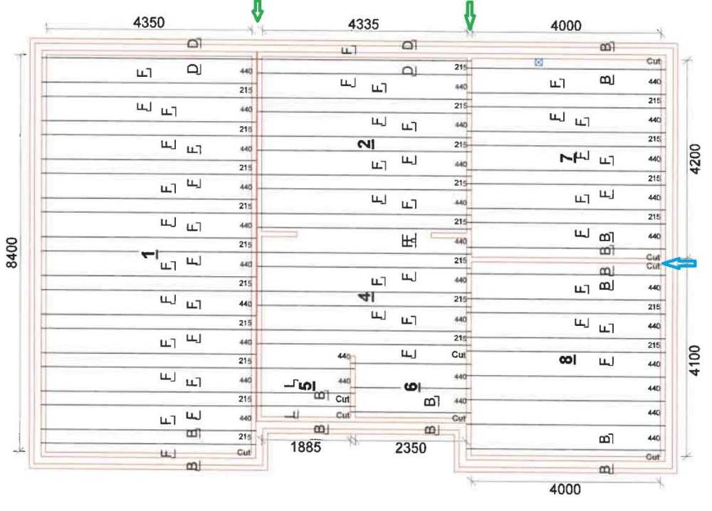
Thank you, @Big Jimbo. Here's the beam plan, in case that's any help. There are sleeper walls under the B&B. The two longest of these are indicated by the green arrows. The sleeper wall indicated by the blue arrow wasn't built. There's a double beam here instead. I asked (paid) a proper builder to come on site to inspect & report on the work. His opinion was that we could build off what was there, but we'd have to take the airbricks out & re-fit them properly. Of course, if we build off what's there, we're going to have to accept the B&B floor will be a lot more damp than it should be (higher U value) & our only protection from the excessive damp will be the membrane that goes on top.
-
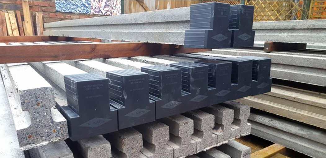
& these are the K-Kaps. You can see the rebar at the ends of these beams. My beams have no visible rebar. I hope you don't mind me jumping in on your thread, @Glee. I think @Canski has told you everything you need to know, anyway. Should I get my trolley jack out?

-
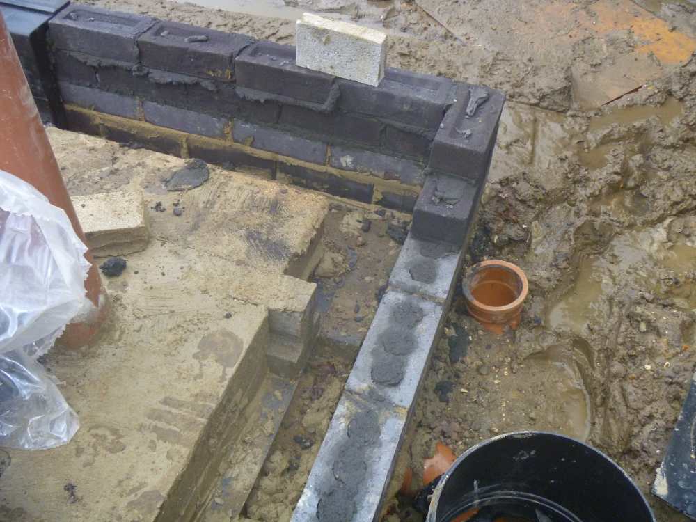
Ripped DPC in the red circle & DPC doesn't reach the inside edge of the blocks.


-
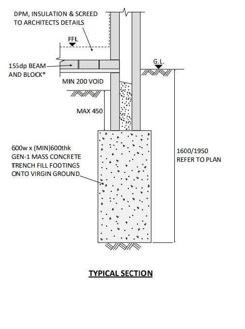
I only had a quick look at the reg.s, but they don’t seem clear. I think what you say is true for beams with exposed rebar at the ends, but not all beams have this. What do you think? This mess, below was built by my cowboy builder, before I got rid of him. He was supposed to build according to my drawings (2nd picture), but what I’ve ended up with is trench blocks going up above ground level. The beams rest on the trench blocks. There’s DPM beneath the beams, but it’s not really doing much, because it only goes (almost) as far as the end of the beams (& doesn’t go right to the inside of the trench blocks either). Also, the builder has bridged from the trench blocks to the beams with big dollops of mortar. This might not be such a cause for concern on most plots, but I have a very high water table, so water is going to be rising up through these blocks into my beams. I’d decided to build off the top of this mess, but lately I’ve been considering removing all the blocks, jacking the ends of the beams up with a trolley jack, putting some wider DPC in there & capping the beam ends with K-Kaps (picture below). Is this idea worth further consideration? It would be good to hear some opinions from those in the know, please.
-
Yes, I think you're right. The gap will be bigger than shown in the black diagram above, because the tray would go on top of the lintel on the outer leaf, but if this were a wide first floor window, with few courses above, I wouldn't expect beads to flow all the way across. So if you're doing it yourself (rather than relying on your brickie) you could cut some solid insulation, & get a good tight fit, or perhaps you could get the bead installer to pump in from the inside, directly behind the tray - probably a bad idea - I'm full of them.
-
I still think that. + a tray costs next to nothing, so why wouldn't you?
-
I'm just guessing, but I should think people use the other Catnic lintels - the kind with a thermal bridge, because they're cheaper.
-
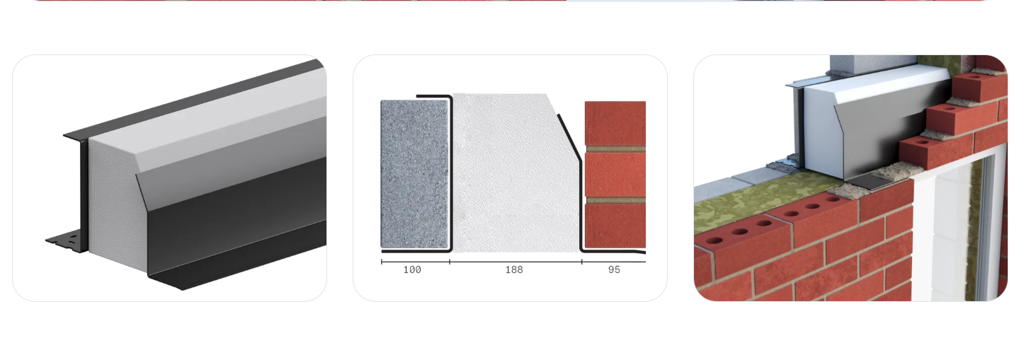
May I just check, the tray (blue line above) goes beneath the lintel, as shown - I think it might go above. & I'll just remind you, I know next to nothing.
-
The Catnic split lintels look good to me. I know next to nothing, by the way, so don't take this as advice. I'm just wondering how these compare, performance wise, with the (presumably cheaper) option of two separate steel reinforced concrete lintels.

-
Good analogy. @Iceverge talks a lot of sense, as usual. My own experience was that the council didn't take too much notice of the neighbours' objections, so it was just the planning dept I needed to work on. Eventually, I was able to wear them down & achieve PP for something that was worth building. Once I had PP, I was able to bolt on a little extra something, via a non-material amendment application, that I had removed from one of my original designs, as part of the compromise arrangement to achieve PP. The planning dept were more concerned about the ridge height than any of the many other aspects of my design that they didn't want. I chopped the top off my pitched roof design - so I have two ridges, with a long flat roof in between. It will still look like a conventional house when viewed from the street/driveway entrance & the house still has good depth - just an idea you may be able to use. Achieving PP can be a frustrating & lengthy process, but I'm sure you'll have something you're really happy with by the time you finally get there.
- 61 replies
-
- 1
-

-
- design
- grand design
- (and 4 more)
-

Planning Approved - Feedback on proposed layout
Tony L replied to Owain1602's topic in New House & Self Build Design
I think the recessed full height glass into the double height entrance hall is a really nice feature - the rising sun likely won't get in there as it moves around to the living room side in the morning. I'm no expert, but I think you're going to have too much solar gain from all the south facing glass to the living room side. Perhaps you're planning to spend the extra for solar reflective glass. If your architect is used to working to PH standards, perhaps he can plug your design spec' into the PH software that will tell you about solar gain, cooling requirements, etc. -
That's been on my to do list ever since the 'van arrived (ie make a skirt on a lovely warm summer's weekend, to feel the benefit in the winter) - I know that's what you meant.
-
How much is a stone built outbuilding worth
Tony L replied to Triassic's topic in Costing & Estimating
The situation isn’t clear: it’s her building, but it’s in your garden. How did that happen? It sounds as though you already own it if it's in your garden. You don’t say how much land is included in the building’s sale. I’m assuming this land is adjacent to your garden. Does it share a boundary with any other properties? Might other people want to buy it? How much it’s worth entirely depends on who’d like to buy it & how much these prospective buyers are willing to pay. If it’s in your garden & you’re the only prospective buyer then it’s not worth very much (unless you have let slip that you want this building very much). If the vendor might be selling their house any time in the next decade & the building might form part of that sale then that will make it worth more than “not very much”. I’ve perhaps not been very helpful so far, but it may help you if I explain, I bought a strip of land (approx. 2m x 16m) to increase the size of my very small back garden. This was worth a lot to me, because adding 2m to the length of my small garden has made a big difference. I offered £5,000 for the strip of land to the developers that were building the neighbouring new build + I said I’d pay all the solicitors’ fees. The developers said they’d spoken to the local estate agent (whom the developers & I both know & trust) & the agent said it was worth £10k. I said, it probably is worth £10k, but nobody other than me will want to buy it & I only have £5k to spare, you’re not going to miss a tiny slice off your big back garden & it’s £5k straight onto the margin you’re making on the new build house, which you definitely will notice. He agreed. I did some drawings for my solicitor, who acted for both parties (£400 four years ago). I think there was some small land registration fee to pay as well. The developer built & paid for the new fence on the new boundary. The entire process was very easy – certainly a lot easier than hiring a builder to complete some seemingly straight forward tasks. Hope this helps. -
Dormer construction detail advice, please
Tony L replied to Tony L's topic in General Construction Issues
Thanks, @Russell griffiths. My understanding now is: I should build almost all of the dormer by continuing the ground floor cavity wall up to the flat roof on top of the dormer, as suggested by @ETC . I made a mistake with my mark ups on the previous Sketchup & there’s a new one below showing the section that will be in timber, behind the diagonal orange lines. I’m thinking the problem with lateral loads is now solved, because the outer edge of the timber section can be built off the pitched roof rafter, like a normal dormer. The cavity will be closed off with a cavity closer, where the blue line is. My problem now is, how do I attach my first studs to the ends of the 100mm wide blocks on either side of the cavity, where the blue line is. I don’t think I should be drilling into the ends of the blocks, in the same way you could drill into the face of a block wall. Perhaps I should use L-shaped brackets fixing into the centres of the full block faces. & should I put frame sealant on the ends of the blocks before offering up the timber stud or is there a better product to get these to fix together well & allow for the timber to expand & contract? Perhaps this is not worth worrying about so long as I get my airtightness detail right across the masonry-timber junction. Any thoughts on the above would be most welcome.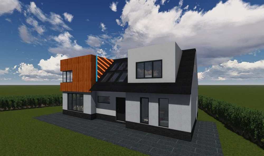
-
Dormer construction detail advice, please
Tony L replied to Tony L's topic in General Construction Issues
I don't think that's an option now. For reasons I won't trouble you with (as there are so many), the B&B floor is already built, with the 215mm sleeper wall beneath. Also, I wouldn't really want to waste space with a cavity wall inside the house when I'm sure there will be a solution based on a 100mm wide block wall. -
Dormer construction detail advice, please
Tony L replied to Tony L's topic in General Construction Issues
Here's an update of my diagram showing the dormer plan on top of the foundation plan (just so we can see how it all lines up). Any comments on this (positive & negative) will be gratefully received. Are there any colour conventions I’m flouting as I draw my diagrams (eg airtight layer is always shown in red) or does everybody just choose any colour they fancy as they make each drawing? I’m using MS paint, & I can’t figure out how to get the neat S shaped squiggles that usually represent insulation.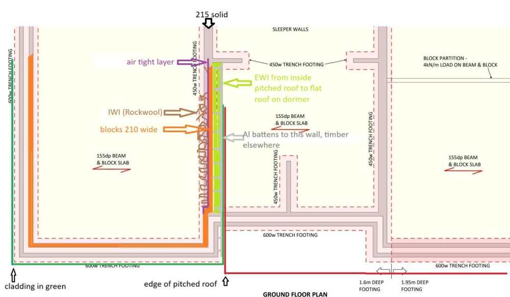
-
Dormer construction detail advice, please
Tony L replied to Tony L's topic in General Construction Issues
Thanks @Russell griffiths. That sounds like a good idea, but it’s going to need some thought to make it work. Although you say “cavity wall coming up against the roof”, my current understanding is it won’t be a cavity, it will just be a continuation of the inner leaf from the cavity at the front of the house, & this single skin block wall will sit on the edge of the 215 wide block wall, so the wall from the hall up to the landing area above will be a nice flat surface, ready for wet plaster. My current front runner for the cladding (Dura Cladding Flush Resist) is designed to fit to 25mm Dura Aluminium bearers (will be 50mm by the time I’ve got them going both ways for vertical cladding). They’re expensive, of course, so I’ll be using wood for the cross battening for the walls other than this awkward cheek. I didn’t know anything about EWI until I started Googling 30 min.s ago. I realise now, I can’t just stick 135mm+ EWI against the single skin block wall then 50mm crossed battens, due to the lateral loads (the cladding needs to be 185mm+ off the wall we’re talking about). I found this diagram in a cladding handbook. There’s some cold bridging, but it’s only a small section of wall, so perhaps I shouldn’t worry about that. I’m assuming wooden battens with EWI in between is not going to work, so perhaps I could source some bigger aluminium brackets/battens to get to 160 off the wall, with 150mm EWI embedded in these then the 25mm Al horizontal battens on here (not sure if the air gap is desirable/necessary behind composite cladding) - I could pack the whole 185mm out with EWI. The heaviest part of the triangle (at the front of the dormer cheek) will be going onto the small section of cavity wall, so the battens won't have to reach out very far here, which is good. Any thoughts on this anyone? Do I need to think about using VCL with EWI in this scenario?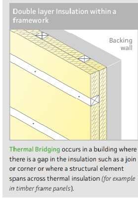
-
We got ours from O'Leary caravans OX2 9BY. It's a 37 x 12ft. They told me how to prep' the site then they delivered it, moved it into position, levelled it. My partner did all the negotiation & bought it. I didn't see it until it arrived, but I was very pleased when I first saw it, & it's been a good buy. Perhaps it helped that she has Irish roots & an Irish name, but I'm giving these guys 10/10 for customer service & value for money. It looked great on the outside, but very tired on the inside. We removed all the built in furnishings & redecorated. We turned the master bed room en suite into extra storage. We replaced the built in seats with our sofa from the old house + an armchair. Flowery curtains replaced with pale grey roller blinds, no more flower prints on the walls. It now looks very modern inside. If I'd had more time, I'd have crawled underneath to fit insulation, starting with the middle section where all the pipes hang down. I must add that, although it's a great place to be when the weather's right, we both have other places where we can stay, so we're not there all the time. Ours didn't come with a boiler & we're just making do with oil filled radiators. Good luck.
-
Dormer construction detail advice, please
Tony L replied to Tony L's topic in General Construction Issues
Sorry: on re-reading I see this is ambiguous because I used orange again on the next drawing. It's the dormer cheek marked with diagonal pale orange lines on this drawing, below, I'm struggling with.