Tony L
-
Posts
385 -
Joined
-
Last visited
Everything posted by Tony L
-
 Thanks @SteamyTea. I don't have plans in a suitable format to upload here yet. I have my original PP drawings, with lots of annotations hand written onto them. I don't have U-values - I'm hoping to find a competent person to decide on the build up of the various external surfaces & work out all this for me. Once I have drawings worthy of BH's attention, I'll upload them & invite criticism. Thanks again for your offer.
 -
Thanks @LiamJones. That's impressive work you've done there. If I get to build a second house, I'd like to try to do what you've done. I did the PP negotiation/drawings myself, but I just don't have the time to fill the gaps in my knowledge then set about dealing with all this myself. I have a business to run, an elderly mother to look after (still in her own home) & other commitments (I'll spare you the details), so I just want to pay a competent person to deal with the drawings so we can get the full plans approval & start building the superstructure. We've already built up to our B&B floor under building notice. & we need the drawings to get a QS estimate as well - then we may need to change the spec' to fit our budget.
-
I didn't actually sack him - he's waiting for me to annotate his drawings & point out all the errors (this is a lot of work as there are so many errors). I'd rather start again with somebody new, who is competent & will make all the difficult decisions for me - such as wall/roof build up, insulation types, membrane types, what happens at all the surface junctions, etc. Each time I start a conversation with somebody new, it costs me a lot of time - only to find out they can't do what they said they'd do. I'm under a lot of pressure from my partner, who is angry & impatient. She's at the stage where she just wants a house that looks really good & can be built within our budget; she doesn't really care if it costs a fortune to heat in winter & overheats in the summer.
-
That's right: I don't really need a PH certified person to do these drawings for me, but I thought, if this man has drawn PH houses then he can definitely draw what I want, - let's call it BH principles, rather than PH principals. I've come around to the view that most of the people who do architectural drawings are stuck in the past & they only update their knowledge so their work can just scrape through the latest building reg.s, & that's not what I want.
-
Thanks, @ProDave. I’m on board with all of this, but it’s good to hear it again from one of the BH experts. With a 150 cavity & blocks either side, I can’t see that we’re going to do any better than 1.8 U value for the block walls, although I will look to fatten up the dormer walls so we do better there. I have plenty of space for deep warm flat roofs, but I’ll be compromising on the sloped roof insulation, so it doesn’t take too much space from the rooms under the sloped roof on the back of the house. I don’t think 3G everywhere will be affordable. If I can, I’ll have all the windows in the sloped roof in 3G, as there’s more loss through a window in a 40 degrees roof than if you stick the same window in a wall. & 3G in the roof windows will help mitigate solar gain too. I’ve done a lot of reading here on BH, so I have a good idea of what I want. The architectural technician who’s been doing the drawings for me took my brief, which included detailed explanations of how I want things to be. He claimed to have understood it & has drawn something that’s not even the same shape as my design, has a much higher ridge height, gas boiler, ME vents, cold bridges all over the place, & all sorts of other mistakes. I decided to cut our losses with this guy & try to find somebody else to do our building reg.s drawings & construction drawings. I spent a lot of time briefing a PH certified architect, who said he could help me & then another architectural technician, who claimed to have just completed an air tight project. The PH guy’s quote came in & it was thousands of pounds more than he’d said it might be after our initial long phone conversation & face to face meeting. The architectural technician, who was very keen when my partner spoke to him, said he no longer wanted the job, once he’d seen my brief: which he said was very detailed & a bit frightening. I got the impression he likes to work for customers who know next to nothing about how their houses should be built. So it could be a case of going back to the arch tec who gets everything wrong & making every last decision myself, then telling him what corrections to make to his drawings. This is going to take forever & I’ll be asking a lot of questions here – that’s why I was planning to pay more for the proper PH architect, who I expect would have known exactly how to draw all the details, without any guidance from me.
-
Thanks, @nod. That's my way of thinking, but the problem is, I'm certain we'll be there for a minimum of three years, to avoid the CIL payment, & more than likely we'll be there longer, so I want it to be a good place to live, but I don't know about four years from completion onwards, so we're not building with a forever home mentality. My partner is different from me. She is very focused on the house being worth a good deal more than we're going to have paid for it. That's good to hear, but how much is not a lot? Less than £12k? I'm very focused on the numbers that have a "£" in front of them, & the missus is, even more so.
-
Yes, the shape/form factor is far from ideal. My early designs had good form factor, but due to planning constraints, I was forced to choose between a bungalow & what we've ended up with. I don't have time to do the detailed mathematical modelling, you suggest, @SteamyTea. I need to make progress before my relationship disintegrates - I'm hoping for some estimates of additional cost to build, & perhaps also reduced costs to run, based on BH experts' knowledge & experience.
-
My partner (it’s half her money) has been speaking to someone who we approached to help us with the superstructure drawings, & he’s told her, unless we know we’re going to live in the house for 10 years, making it air tight is a waste of money because we won’t sell it at sufficient premium over a "normal" house to get our money back. He says we’d have to use a specialist eco builder & they cost a lot more. I’m thinking, if we have good construction drawings & we choose a builder that is comfortable with the concept of airtightness, we’ll be OK, if I’m on site to inspect the work at least every other day, & issue instructions, as necessary. We haven’t yet got superstructure drawings that are good enough to give to QS. So my question is: about how much more will it cost to build an airtight house than if I build a leaky house? I see the main costs being: MVHR system (£6k, if I do some of the installation work?) Membrane, tape, purple paint Ledger boards & hangers where FF joists meet exterior walls Additional construction hours – it’s sure to take a lot more time to get the details right & there’ll be a small saving on radiators, pipe work, etc upstairs. Obviously (to me at least), it’s more about comfort than payback times, but about how much could I expect to save on my heating bills each year (SE England & heating via ASHP)? I was thinking the answer to this might be around 70% - that’s just a wild guess , so if anybody has proper knowledge, please speak up. Of course, the easy answer is, “It depends…”, but please work with me on this & suggest some figures.
-
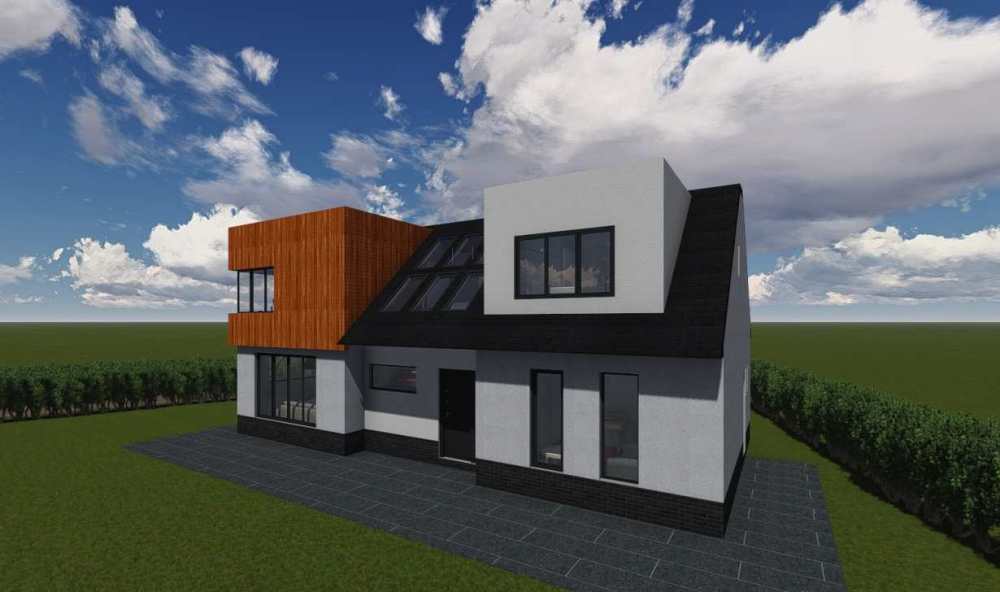
I’m building a house that will look a bit like this: 124m2 footprint , around 114m2 GIA downstairs & 75m2 upstairs. Block inner leaf, block outer leaf with render. Although I’m only planning for 150mm EPS beads in the cavity, I’m intending for there to be sufficient insulation upstairs to eliminate the need for upstairs heating. I’d like to see a 0.6 air tightness score.
-
How bad is this brickwork & should I start again?
Tony L replied to Tony L's topic in Bricklaying, Blockwork & Mortar
That's impressive work for an amateur, @Pocster. I laid a few courses of blocks 30 years ago, when a friend was building a garage for me, & I was surprised at how bad I was at it. -
How bad is this brickwork & should I start again?
Tony L replied to Tony L's topic in Bricklaying, Blockwork & Mortar
I’ll just tidy this thread up: The builder employed a firm of solicitors (quite a big firm from up north) to assist him in his attempt to bully me into paying outstanding bills totalling £10,873. There was a long exchange of emails, which I hope was costing him dearly (it didn’t look as though he was writing all these himself). I decided I probably wouldn’t need to engage a solicitor to help me until we had a court date. Of course, the builder was using lies & flawed logic to argue all his work was absolutely fine. In the end, he sent a credit note for £6,873 & I paid £4,000 to resolve the dispute. In order to get the credit note, I had to agree to not come after him if any defects, in addition to those I have already told him about, come to light. I’m not happy about this, but I decided to take the risk, so I could move on. This was the second credit note I’d received from this builder. The first one (£6,800) was received after a long argument over the cost of the extra works BCO insisted on after changing their mind about the foundations. Part of me really wanted to resolve this in court, & see him crumble as I presented my cast iron case, but as anyone who uses reputable sources to follow current affairs knows, the justice system in England & Wales frequently works against victims, so I decided not to gamble on it working for me. -
Yes, I like to know what kind of rubbish people are reading, so I read a variety of newspapers. When I bring one of my mum's previous day's newspapers to the office, I keep it hidden so nobody gets the false idea I'm one of those people that agrees with the newspaper's world view.
-
The white streaks could be efflorescence. This normally appears as patches, rather than streaks. Efflorescence is caused by salts dissolved in water rising up through porous brick/block work; the water dries, leaving the salts behind. Perhaps somebody with more knowledge than me will be along to tell you what you can do about it. You should be able to wash/scrub it off, but unless you treat the wall in some way it will return. If a wall is built with a DPC entirely above ground level, efflorescence should only appear below the DPC.
-
Cost to Discharge Condition
Tony L replied to Rosslyn's topic in General Self Build & DIY Discussion
£43 when I submitted a revised external materials schedule recently (different roof material, cladding & other minor changes from what had already been approved). -
Gross Internal Area. Even I know that one, & I know nothing.
-
Community Infrastructure Levy (CIL) HELP PLEASE
Tony L replied to Caroline's topic in General Self Build & DIY Discussion
If I were you, I'd be asking the council for clarification on this, rather than Build Hub, but it looks to me as though this is just a standard letter they send out for the more usual circumstance of a new build replacing a dwellinghouse, rather than a barn. Did you complete a CIL exemption form? I expect different LAs may have different rules, but in my case, if I live in my new build for two years following completion, there's no CIL to pay, so whatever floorspace derived calculation has been made becomes irrelevant. -
Are you sure? I've just had a quick look & other than second hand, they're all more than £300.
-
What will they think of next?
-
Assuming the ties are coming into the bricks at height intervals that are compatible with the Drytherm, can't you just cut slices in the Drytherm so the last 100mm or so goes around either side of each tie?
-
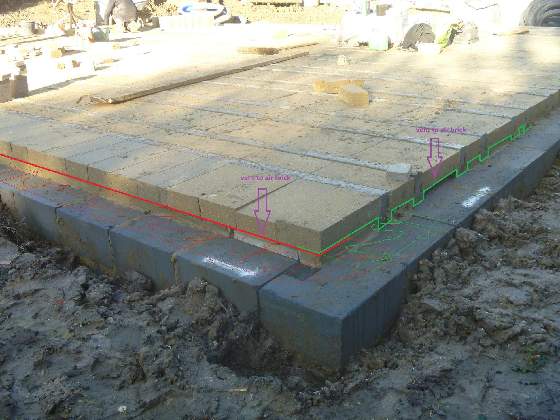
Here’s the diagram I promised you, @crispy_wafer. Just to re-cap, my builder built this B&B floor off trench blocks instead of a cavity. There’s DPC along the inner edge of the trench blocks, but it’s not doing much, because it’s been bridged with mortar. I’m thinking I should take the blocks out & lift the beam ends one at a time, to run 450mm wide DPC along the routes shown in green & red. This will leave sufficient DPC protruding to lap over the top of the edge blocks, to be held in place by the first course of the inner leaf, when this goes on (is this how it’s done?). I’ll leave the cowboy builder’s DPC in place. In the image, below, the thick red line shows where my new wider DPC will protrude from the structure when it’s all been put back together. The DPC shown in red should be easy to install. The DPC along the two walls where the beam ends are needs to go under the beams, of course. I’m thinking I can weave this so it goes over the air brick periscope ends, & I think it might be easier to go over the top of the infills under the other blocks too. This is shown in green. I built a model & used paper in place of DPC, to see how the folds work, & everything looked good. DPC doesn’t fold as easily as paper, of course, so I may end up having to make some cuts, but whatever I end up with has to be a lot better than what I’ve got at the moment. All comments will be gratefully received – thanks.

-
Thanks, @crispy_wafer. I have been thinking along the same lines. I've removed two blocks from the edges just by levering them out with a spade, so I think almost all the blocks could be re-used, apart from those close to where the 110mm pipes, etc, that penetrate the floor, have been grouted in with mortar. I'm thinking a 450mm wide DPC could go in then be lapped up over the top of the blocks. My current plan is: remove all the blocks, lift the ends of the beams, put the new DPC in & weave this below the beams (on top of the cowboy builder's 100mm DPC) over the tops of the mortared in brick slips that go between most of the blocks, back under the next beam, over the tops of the ends of the periscope vents for the air bricks, under the next beam end, & so on. This way, my floor will be isolated from the damp trench blocks & I won't have to make any cuts for the air brick periscope ends. Also, I don't have to hack away at the mortar between the beams & risk damaging the trench blocks. If my description has not given rise to a wonderfully clear picture in your mind, don't think about it too hard - when I have time (tomorrow, if all goes well) I'll post a diagram. I'm thinking a trolley jack will be better than a digger, especially if I want to lift the beam ends from the sleeper walls in the middle, rather than restrict these works to the perimeter. I have decades of trolley jack experience & zero digger experience. & you're right - removing all the builders' packed lunch leftovers is sure to give added job satisfaction.
-
You're right, you're right, although I thought they were still constituents, even if they're below voting age, but I'm probably wrong on that too. Hartlepool, where my family is from, is definitely more insular than the SE, & in a good way: most people have a far greater understanding of local issues there than they do down here in Surrey. The question was: Can you help me build my house, please? My nasty Southern builder has done me over & I'm struggling to decide on the extent of remedial works (see my recent posts).
-
That'll teach me. I'm supposed to be working, so I can afford to build a house. The source was my head - just a vague notion I'd formed having watched so many Scottish MPs speaking in the House of Commons (watching them on telly, that is - I've never been there) & looking at those constituency maps that are in newspapers around election time. So, if Google is to be believed (& very often, it isn't). mid 2023 England pop = 57,690,300, Scotland = 5,490,100. From 650 constituencies, 543 are in England & 57 are in Scotland. That gives 106,243 constituents per English constituency & only 96,317 constituents per Scottish constituency. So your average MP representing a constituency in England is looking after more than 10% additional constituents when compared to the average MP in Scotland. & I wouldn't dare suggest that there may be more than 10 times as many Scottish born MPs representing English constituencies than there are English born MPs up in Scotland, because I might have to spend the rest of the day Googling to support that claim. Now, I must concede., although this bias in Scotland's favour is significant, it's not quite as bad as I thought & probably less than the skew in wind turbines. If you or @ProDave want to tell me I've got my facts wrong, I'll agree with you, in the hope that this will encourage you to continue to help me build my house. It's got off to a bad start, & I need all the help I can get.
-
I'll agree with you @ProDave. While we're levelling up, let's also deal with the problem of Scotland having far more than its fair share of MPs. Each Scottish MP represents far fewer constituents, on average than, their English counterpart.
-
Thanks, @crispy_wafer. Yes, that would be a lot easier, but almost all the damp in the beams is going to be coming up from the trench blocks & the mortar, so sealing the ends of the beams will still leave me with around 95% of the problem unsolved.