Owain1602
-
Posts
38 -
Joined
-
Last visited
Owain1602's Achievements
Member (3/5)
7
Reputation
-
Batteries in plant room and 120 minute fire rated walls
Owain1602 replied to jimseng's topic in Energy Storage
Depends what you mean by “batteries like it hot”. The charge transfer processes can happen quicker at higher temperatures, so if your aim is to charge/discharge the battery at higher rates, then higher temperatures help with this. But high temperatures is the worst factor for increasing degradation rates for batteries. If the battery is LFP, then you have an already high baseline for the battery’s cycle life. -
Insect mesh and air gap for timber cladding?
Owain1602 replied to Great_scot_selfbuild's topic in General Joinery
I’m not sure if your picture is up to date, and reflects the words, but I can’t see double thickness battens around the windows for fire stopping? You need infill battens between your horizontal ones to act as a cavity barrier. Except for the obvious ventilation requirements, the thing that was always in the back of my mind when doing the detail for ours was any water running down the cavity above a window. I didn’t want a surface where this water would sit on, and potentially start migrating back towards the head of the window (or sit on a batten constantly). Might have been overly cautious, but I’d rather that than the other way around. The water could be condensation, wind driven rain etc. Cladding suppliers I have used previously typically want at least 10mm gap at the top and bottom of the cavity. -
@jimseng Are you dealing with BT or OpenReach? I’ve had a great experience dealing with OpenReach so far, for a new fibre connection in a rural area. Virgin quoted £100k, as their closest network was 16 miles away. OpenReach quoted £3k. Our area is not on any of the official development maps, so no plan to roll out fibre to the area within the next 5 years. I put in an application for a new connection, expecting it to be ridiculous. Luckily, the water pumping station that’s half a mile away has a massive fibre connection, which OpenReach can tap in to for our house. I need to trench and install junction boxes every 60m down our 250m driveway, but they are supplying all the ducting and boxes within the £3k.
-
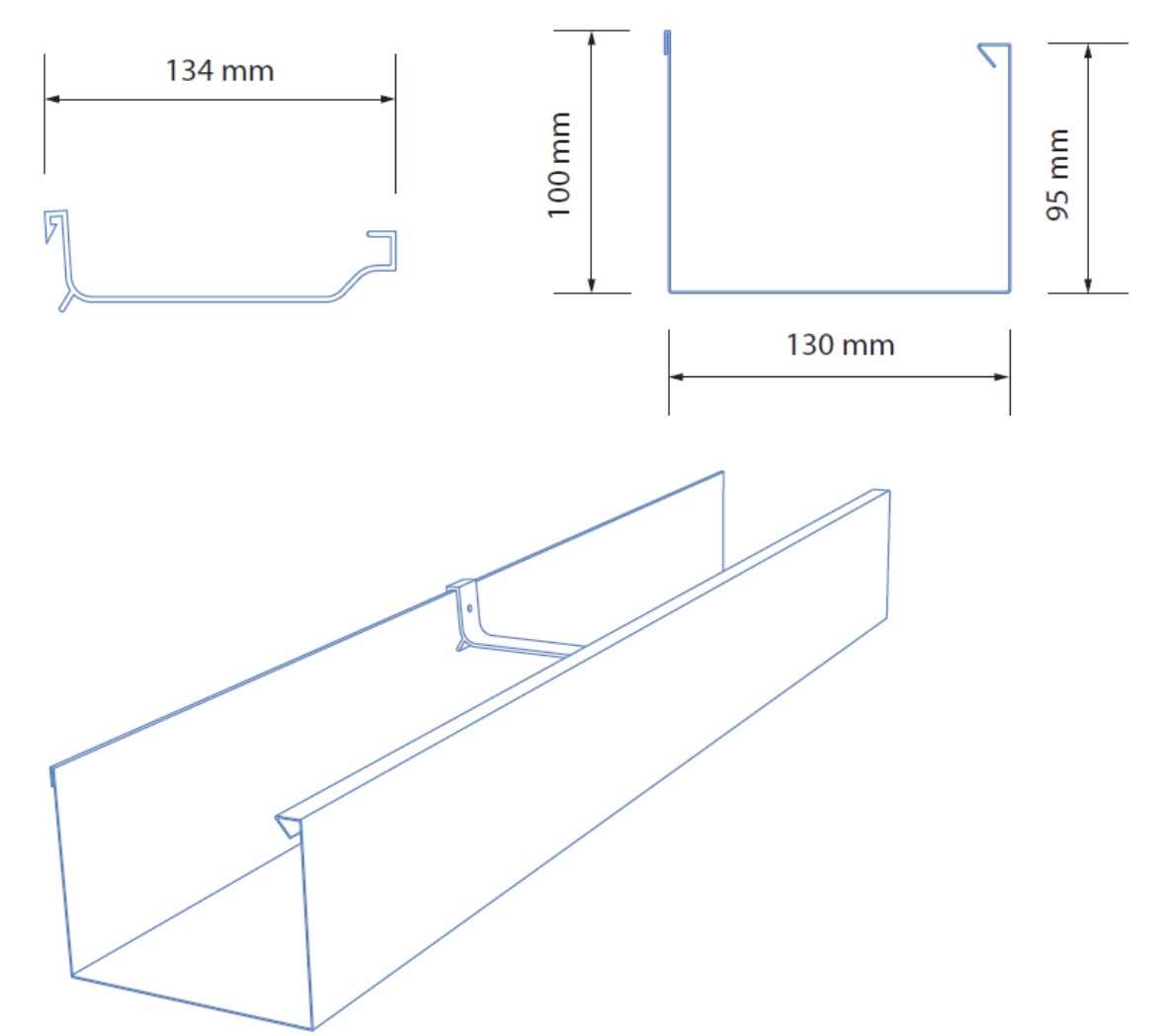
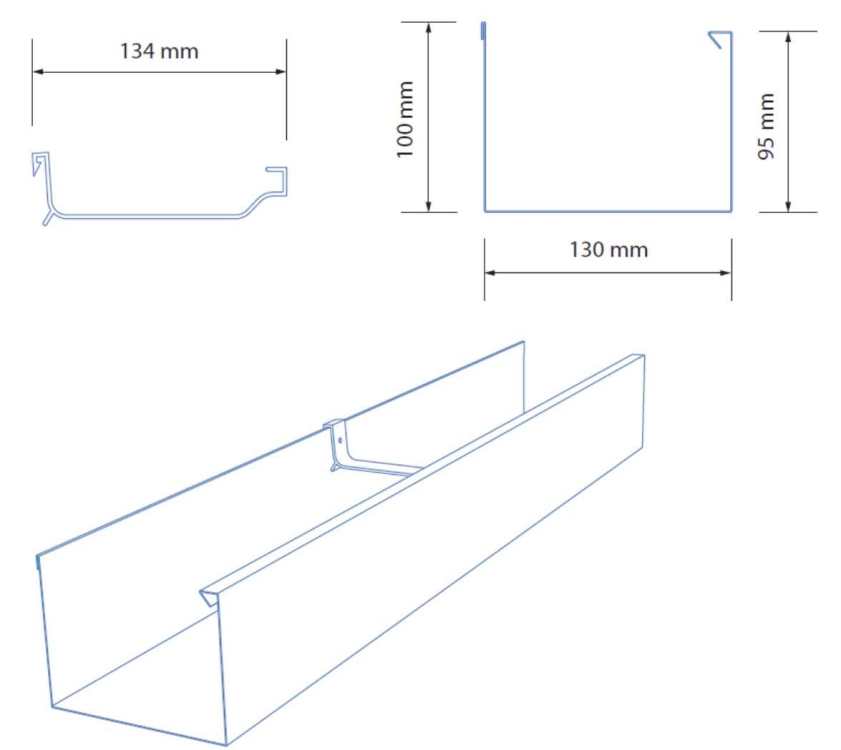
FYI, this is the gutter that Tata supply with their Catnic roof. I can’t make out from your drawing what is cladding, cavity etc. But my understanding is that they want to fix the gutter to the outside face of the cladding (or equivalent timber). I was told by our steel roof installers to bring the top deck of OSB3 out to the same projection as the external face of the cladding. They then make the overhang and drip edge with their metal eaves trim, and the gutter is fixed through the outside face of the cladding to the timber.
-
Cavity closure timber frame
Owain1602 replied to Selfbuildsarah's topic in New House & Self Build Design
You will need to provide ventilation behind both cladding types, MBC insist on it. I worked through all the details for our MBC house a couple of months ago, and put a case together for both building control and structural warranty inspectors to agree. It’s quite tricky if you want to provide proper ventilation, guard against insects, allow the cavity to drain any moisture that gets in there, conform to BR cavity barrier requirements and of course….look nice. Most examples I see just close off the heads of the window reveals, and moisture then just sit against the building. Do you have any section drawings to share what you have so far? -
Have you chosen the supplier for the metal roof yet? There will typically be an eaves trim that gets fixed to the edge of the top deck, with a downturn that sits in the gutter. The metal roof sheets are then swaged to this trim to lock it all together.
-
You are right @Gus Potter, that Protek on the Structural Warranty outsource the inspections and responsibility to another smaller firm. But the smaller company are controlled massively by Protek, and ultimately, it’s Protek that decide if they are happy with the evidence submitted to Surveyor Link. I had one instance where the smaller surveyor company weren’t sure what to do regarding a retrospective watching brief on excavations. They gave me the details and asked me to call the main man at Protek. Explained the situation to him, and he was happy. He told the smaller firm to accept my explanation, and we moved on. Coming back to the original question regarding build insurance, do you also have liability in the policy? As I say, we went around the houses with numerous other companies. Protek were the simplest to deal with (although quotes for rebuild costs over £1M took a long time!). We went with a price very similar to yours for 15 months cover. FYI, Protek are not the insurer, it’s a company called QBE
-
We had/have the same situation. Anything over £1M goes down a different pathway in these companies, and gets a more bespoke assessment. I found that the costs go up disproportionately for anything over £1M. Went with Protek in the end, after looking at others. @Gus Potter You seem to be discussing warranty, whereas the question is related to insurance.
-
We have just gone through this. As @ETC says, easiest thing in most cases is to put in a Radon membrane (Visqueen R400) and sometimes a sump (Damplas one was £50). Insulated raft foundation engineers included full Radon protection in their foundation drawings (as we’re in a high area). Building inspector and structural warranty inspector was all over the details like a rash. Wanted images to show the sump had been installed, gas tight joints on all pipework to the sump. Spent a while inspecting the R400 membrane joints, laps, and in particular the penetrations. We had top hats on most (which must also need a Jubilee clip to secure), but some more complex ones needed a specific Visqueen detailing strip, which is a sticky butyl backing with a thin layer of Aluminium. They also insisted the Radon membrane projects at least 1m out from the walls of the house (under ground obviously). Not much more hassle than using a DPM if done at the right time.
-
Over site prep after foundation masonry. Why?
Owain1602 replied to flanagaj's topic in General Flooring
With all due respect, I don’t think you should be giving any advice. Just because you’re not comfortable to be operating an excavator and dumper around some block work. If you don’t trust yourself, get an experienced operator, or get the bulk of the material well away from the blocks out with machinery, then pick away at the rest by hand. It sounds to me like you should be spending more time doing things, rather than getting every opinion under the sun about how something should be done. Why was the material not excavated before the blocks started going in? No idea the footprint of what you’re doing, but I can’t imagine it would be more than a day of work. Did you ask the guy doing the blocks if you could delay him by a day? -
I see you’ve written that your CIL liability form was “approved”. Do you mean that you’ve signed to confirm you accept the CIL liability (which you must do first)? Or you have had your CIL exemption confirmed? Also, do you have any pre-commencement conditions on your planning approval?
-
Someone acting as my Electrician won't come back
Owain1602 replied to boxrick's topic in Electrics - Other
Did you have a contract of sorts in place with clear scope/deliverables? Then, did you request any changes/deviations to the deliverables agreed in the original agreement, and were these formally documented? You can work with people/companies in many different ways, but you need to tailor your approach to suit the framework that’s in place. -
The planning authorities I’ve had dealings with had Consultation as Stage 4 and then Site Inspection as Stage 5 (total of 10 stages). In most cases, they don’t feel the need for a site inspection, but they would want to factor anything raised during consultation in their site visit. I don’t have experience of extending an existing property, but if CIL is a potential, then you need to be very careful.
-
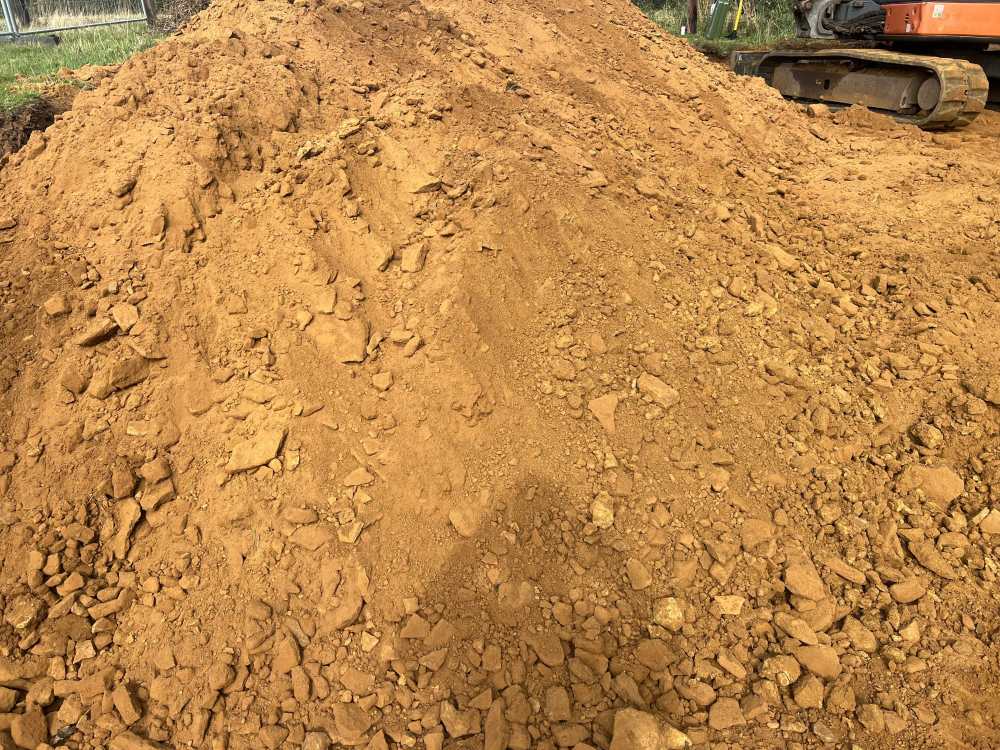
Hello all, I’m currently in the process of preparing ground for an 8x8m steel frame workshop. The area currently has a 1m elevation change from one end to the other. I’m digging in to the bank on the high side, planning on getting a level pad at the height of the current lowest point. Obviously I needed to remove material from the current lowest elevation to remove the topsoil etc, before filling this back in with suitable aggregate. As I’m digging in to the bank to level the ground, I noticed the material coming out looks surprisingly similar to the material I’d be buying in to raise the ground at the lower side. My question is, do you think this material is suitable to bring the levels up (see image below)? I would be using MOT or similar as the final layer under the concrete slab. It’s all dug out and 10m away from where I’d need it. I would lay it in 150mm layers and bring in a heavy plate compactor or even a roller if needed. Workshop will be steel frame, 1m3 concrete stanchion under each steel, with 200mm C35 slab encasing the steels, A252 mesh. As further background for those interested. The site is at the highest elevation in the area, and is predominantly sand and sandstone from about 150mm down. We’ve had a Geotechnical ground survey for our house foundations (approx 40m away), and the ground has >150kPa bearing pressure from 500mm down according to the report. Thanks for any advice!
-
My experience is that timber frame is considered standard construction by the mainstream lenders. What they really don’t like is more than 50% timber cladding. You can find the lending criteria documents for most banks online, which gives a high level overview of their policies on various topics. Some banks have a “special” part of the website for mortgage brokers/intermediates, where they provide these document. Google is your friend here, as a lot of them make it tricky to find the lending criteria from navigating their main site.