MortarThePoint
-
Posts
2198 -
Joined
-
Last visited
Everything posted by MortarThePoint
-
Are those rafters at 600mm c/c
-
Permitted Development During Build
MortarThePoint replied to MortarThePoint's topic in Planning Permission
It's a new build and roof related PD rights are intact thankfully -
Permitted Development During Build
MortarThePoint replied to MortarThePoint's topic in Planning Permission
Annoying as that will be inefficient, but shouldn't add too much cost. Do you have experience or have you seen this written somewhere in 'the rules'? -
What's the situation with permitted development during the initial build? Permitted Development would allow us to add roof lights to our attic space. Do we have to wait for the build to be signed off before then doing that or can we just roll it in to the main works?
-
Wall plate straps (101)
MortarThePoint replied to MortarThePoint's topic in Roofing, Tiling & Slating
Structural Engineer specified 100x50 wallplate, I was just commenting on the article. 140mm screws sound good. Do you use the same pan head screw type you suggested above, or do you use plugs? -
Wall plate straps (101)
MortarThePoint replied to MortarThePoint's topic in Roofing, Tiling & Slating
I saw this article which seems good: https://www.practicalarchitecture.com/blog/how-to-detail-a-wallplate They suggest "Wall plate shall be fixed to wall with Fischer SXRL10mm dia frame fixings 140mm long at max 1m ctrs in centre of wall plate, installed after mortar has set." Could be another place for a masonry screw since he Structural Engineer didn't specify the use of vertical screws through wall plate into masonry, but they seem a good idea. Not sure 75x100 is called for. I had intended to use C24 timber rather than C16 -
How do you seal around that without a frame and flashing?
-
Wall plate straps (101)
MortarThePoint replied to MortarThePoint's topic in Roofing, Tiling & Slating
1.2m is less than 2m so meets the requirement (maximum of 2m centres). Yes it is more straps though -
Wall plate straps (101)
MortarThePoint replied to MortarThePoint's topic in Roofing, Tiling & Slating
Thanks Peter. They are Plasmor 7.3N Fibolite blocks -
Wall plate straps (101)
MortarThePoint replied to MortarThePoint's topic in Roofing, Tiling & Slating
A friend has used 7.5x50 ScrewFix EasyDrive concrete screws to fix his straps to the walls and I'd like to go that way as well: NHBC say: Fixings for straps should be: in accordance with the design, and the lowest fixing should be within 150mm of the bottom of the vertical strap of a material or finish which is compatible with the straps where into masonry, hardened 4mm x 75mm nails or 50mm long No 12 wood screws (into suitable plugs). What have others done? I'm inclined to think the concrete screw will be better than a woodscrew in a plug -
Interesting, thanks. Is toughened glass necessary for a roof light given its largely out of harms way?
-
Has anyone used these: https://www.lbroofwindows.co.uk/roof-windows/centre-pivot-roof-windows/aurora-centre-pivot-roof-window-pine-finish/
-
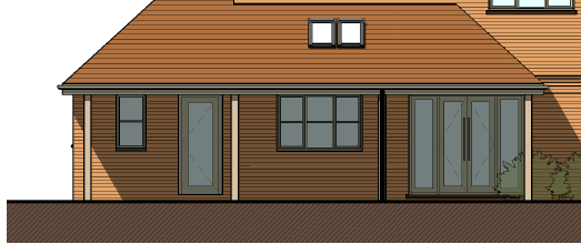
We have a loggia/veranda along part of the rear elevation and there is a window in the wall below it (pictured below). We would like to have a roof light in the loggia roof, but there is no point in it being opennable or double glazed. Can anyone recommend windows that would work well here? Separately, we want to add some non-opening roof lights to the attic space. We would want these to be double glazed, but without the opening mechanism I'd hope we could have a greater glazed area as well as save some money.
-
Maybe I've misremembered the number
-
No internal PIR, 300mm walls with U value of something like 0.26. I did a cost benefit analysis based on 100mm fibre batts vs 125mm or 150mm fibre batts and for me it didn't make sense. I then changed to blown beads very late in the game, otherwise I would have upped the cavity size since the wider cavity economics with blown beads are more compelling. With blown beads there is a fixed cost of labour and a variable cost of beads and so having a 50% larger cavity probably only adds 30% to the cost (guestimate).
-
100mm of EPS beads so similar arrangement just narrower cavity. You could use a concrete lintel for the inner leaf and a single leaf lintel for the outerleaf brickwork. Is there a reason you prefer the concrete lintels? They do look a lot cheaper (Condell seem very cheap). There must be a reason Structural Engineers go for the cavity lintels though.
-
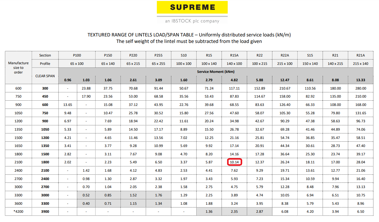
Digging through the Structural Engineer's calculations I see he calculated a requirement of 21.5kN, and specified an IG L1/HD110 lintel with a capacity of 22kN. That was when he was using the wrong cavity size and the equivalent lintel is an IG L1/HD100 with 35kN capacity. ? I've gone with a HT/HD100 with capacity 35kN. 35kN is 159% of 22kN and I calculated that if all the load on the lintel is concentrated on the central 50% (so between 0.45 and 1.35 out of 1.80 span) the moment is 150% higher than if UDL across full span. The actual positions are better than mid span bearing, but this provides a useful worst case presuming ~45degrees of load spreading under the truss bearing. Quite relaxed now. I'll await confirmation from the lintel expert and keep the PCC option up my sleeve if needed.
-
The load/span table has lower figure than the CE cert so looks like 10.14kN/m --> 18kN. Not sure why the figure is lower. https://www.supremeconcrete.co.uk/media/2620/prestressed-lintels.pdf

-
It is challenging to say the least. Even more so when doing it for the first time
-
I'm using HiTherm+ lintels which have reduced cold bridging above windows but are mostly made to order, so not quick to get. The Structural Engineer made a note of the drawings which I didn't understand, but now do, which says avoid multi-truss bearings above lintels. This means avoid things like hip trusses and velux trusses/rafters bearing above the lintel. I've asked the lintel manufacturer to check the situation, but they are being a bit slow. In parallel I want to consider my options to add strength. The spans are 1800mm. Lintel specified is HT/HD100 with capacity of 35kN. First floor, 525mm below top of wallplate, 4 brick courses on outside. I'm not a Structural Engineer, but some logic suggests the following options could help: Upgrade to an XHD lintel (50kN capacity), but there are difficult lead times and circumstances there Add a Box lintel either screwed to the rear flange of the cavity lintel or more easily with a course of coursing blocks between (or just a mortar bed between?). A standard box lintel has capacity of 30kN so should add something useful (i.e. somewhere between 0kN and 30kN :-). I am sure if screwed on it would add its full capacity. With a course of coursing blocks I'd hope it would add at least half its capacity giving 50kN total?? Add a precast concrete (PCC) lintel. R15 2100mm has a load bearing capacity of 22.82kN/m so 1.8m should give a total of 41kN. This could be bedded straight onto the flange of the cavity lintel so I'd expect it should add a fair amount of strength. PCC may have a different allowable deflection at capacity so may be complex working out combined strength. Construct a broken lintel using a box lintel (2100mm standard 30kN, HD 50kN) and a single leaf lintel (e.g. IG L10 2100mm has 10kN). Brickwork only weighs 1kN. Options 2 and 3 are the easiest, but in most scenarios involve laying the lintel of a full lenght bed of mortar. Does that worry anyone? Does anyone have any thoughts as to how the lintel strengths may add together? It's crazy times at the moment and particularly for lintels it seems.
-
Have a long hard think about what lintels you might need and get then on site ASAP
-
Velux type windows in RiR attic trusses
MortarThePoint replied to MortarThePoint's topic in Skylights & Roof Windows
Thanks Peter. Crazy really, so you die falling from the roof rather than roasting to death due to the fire. The rules are the rules. -
Velux type windows in RiR attic trusses
MortarThePoint replied to MortarThePoint's topic in Skylights & Roof Windows
Yes I wasn't clear, the challenge is on the other side of the <1100mm cill ? -
Velux type windows in RiR attic trusses
MortarThePoint replied to MortarThePoint's topic in Skylights & Roof Windows
Pretty much spot on, it adds £550 for 4. 1100mm cill may be a challenge as it's a long way down. off the roof -
Wall plate straps (101)
MortarThePoint replied to MortarThePoint's topic in Roofing, Tiling & Slating
Don't want to annoy the Structural Engineer so will try to observe the 1200 centres, but have a strap immediately either side of openings and if the opening is >1000mm have 500mm long strap(s) in middle. 1.2 is no more than 2 ?