


MortarThePoint
-
Posts
2198 -
Joined
-
Last visited
Everything posted by MortarThePoint
-
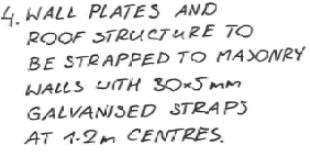
Structural Engineer has specified 30x5mm straps and their c/c distance, but not their length. Any thoughts on what length to use for wall plate? Obviously above any openings they shouldn't be long enough to reach the opening ?. The top of wall plate is 525 above top of frame so I guess that means max. 500mm straps there. What do people recommend for panels? Other perhaps more daft questions: I presume the strap goes down the inside of the inner leaf rather than down the cavity Are the lengths generally stated as plus or including the bend? My inner leaf is 100mm. If the bent bit is 150mm should it be cut or not bother?
-
Velux type windows in RiR attic trusses
MortarThePoint replied to MortarThePoint's topic in Skylights & Roof Windows
The truss designer is talking about doubling up the whole truss, but I don't understand why the whole truss needs to be doubled rather than just the rafter part. Doubling the rafter can be done on site with the benefit of time whereas doubling the whole truss requires a lot more thought -
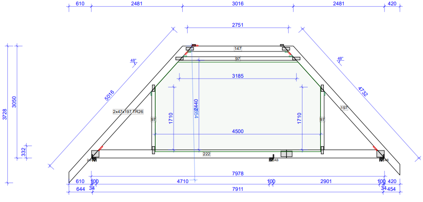
I was thinking of incorporating Dormer window provisions into a roof truss design to allow for future conversion, but have changed my think on that in large part because it needed too much input at the truss design stage. Another reason is that it made for big gaps between some trusses. I had thought I could simplify matters by using Velux windows instead. It normally seems to be simple to fit Velux windows by doubling up the rafters on each side, adding purlins top and bottom and then cutting out sections of any rafters in the middle. I spoke to the truss designer and he said for attic trusses it wasn't that simple. I don't understand why. Is it because attic trusses have bending moments on their members rather than just the tension and compression loads of a fink truss? Even then I still don't see why it's anything more than doubling up the rafters either side rather than the whole truss.
-
Looks smart. Is this over a non-enclosed space (e.g. porch)?
-
I'm considering lead alternatives for the flashing. Perhaps Zinc, but a supplier has quoted to use Wakaflex. Are the rubber type flashings any good? How well do they stand the test of time?
-
I'm still not convinced I have made the correct decisions with all this, but the roofers have said they can work with it so fingers crossed
-
@farm boy that looks like a fantastic job.
-
Surely you have to over bay windows or any enclosed spaces?
-
Truss spacing - 600mm centres
MortarThePoint replied to MortarThePoint's topic in Roofing, Tiling & Slating
Sorry for the delayed responses, I was busy on site achieving nothing ?? -
Truss spacing - 600mm centres
MortarThePoint replied to MortarThePoint's topic in Roofing, Tiling & Slating
In alphabetical order: Donaldson, Pasquill and Truss Form. I've found Pasquill very helpful so am leaning towards them. So 400mm is a thing of the past then? -
I've had some truss designs from some suppliers and they have all gone with 600mm centres. As I understand it that's the normal way to go these days. Does anyone go for 400mm centres any more? There is a housing estate near us that has lots of slate roofs and they look bad after 5 - 10 years. Not due to the slate, but looks like the underlying timber has shifted over time. We're going for plain clay tiles, but this has made me think about whether too many savings are being made on trusses. It's interesting to see the sizes of timbers chosen by the suppliers for the top chords (i.e. the actual roof slope). One supplier has designed based on 47x147, another used 47x197 and the third used 47x222. There was more agreement over the bottom chords with the same first one going for 47x197 and the other two going for 47x222. The one with the slighter timber wasn't the cheapest either.
-
So you end up with a constant with band of lead on the wall at the same slope angle as the roof. What's done with the cavity trays then?
-
Thanks, do you have a drawing or photo of this as it's difficult for me to get my head around. Do you still do the same thing as in my first post with stepped cavity trays though?
-
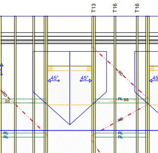
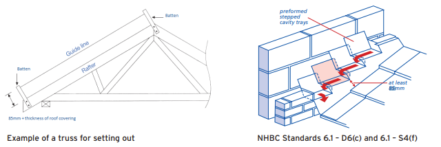
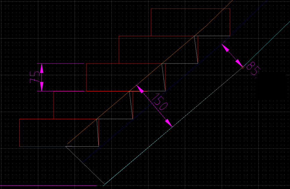
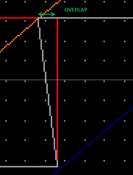
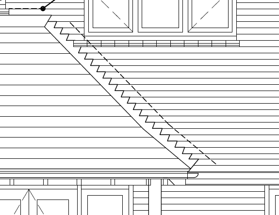
I'm trying to work out where the flashing and cavity trays will sit on a roof abutment. I don't have the rafter to put in place and measure off, but I do have a drawing of the bay window roof exterior surface. I need to work all this out so I can get the positions of the stepped cavity trays correct as they get built in to the wall now. Their corners align with the corners of flashing, so it's lead me to try to understand this (excuse the pun). I can see NHBC recommend at least 85mm (some of their docs have 65mm min) between the roof surface and water line which defines the positions of one set of corners of the flashing. What I can't work out is what sets the position of the other set of corners. Is it just set by the height of courses and drawing a line perpendicular to the roof slope? I've seen something that suggests they sit on a line 150mm from the roof slope. I have attempted to draw this below with the lead shown in grey and the reference lines at 85mm from roof slope and 150mm from roof slope. The red rectangles show coursing and would be the positions of stepped cavity trays. Wider lead flashing or moving it off the roof slope slightly (so up the soakers a bit) would create a tighter angle on the 'saw teeth'. I imagine these must never result in the cut line sloping the other way. Is there a minimum amount of overlap on each step? Finally, can you stop when the lead goes past being vertically above the end of roof slope or is there a minimum amount it has to go past the end of roof slope. In the example below, could I have stopped one brick course higher at the bottom? Lots to understand so thank you if you made it this far.
-
Cavity Tray at roof abutment
MortarThePoint replied to MortarThePoint's topic in Roofing, Tiling & Slating
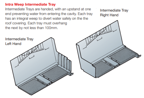
I'm tempted to go for these which look good. Has anyone used them or have anything to suggest? http://www.glidevale.com/uploads/a241ee6cbc0b69457c89339f2886b778.pdf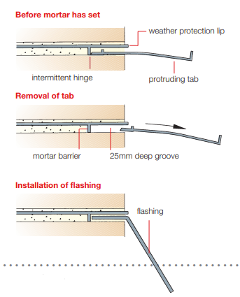
-
I find that often when you are asking merchants about a product and you have to explain what it is, it means you may be trying to do something odd. Neither SIG nor Jewson seem to carry stepped cavity trays which I find strange as don't they get used a lot? We've got various roof abutments that as far as I understand need these: single storey side room that meets main house hipped roof above a bay window porch roof between two returns hipped veranda roof The architect has drawn them on all of these (example below), but I was wondering if they are actually needed for [3] and [4]. The cavity trays make sense to me when the wall below the roof is going to be internal and therefore you can't have weeps lower down. The porch and veranda are open to the outside world below the roof so the cavity trays seem pointless.
-
Movement Joints between brickwork and blockwork
MortarThePoint replied to MortarThePoint's topic in Brick & Block
We've got a single storey utility room at the side of the house and there is a section of brickwork wall above it. I was wondering whether the area shaded in red in the image below should to be brickwork of blockwork. This area is on the side of the main house. The SE have called for a movement joints between the external leaf blockwork and brickwork. This red area sits above the blockwork in the wall between the kitchen and the utility room. I guess the options are: Blockwork: if this is the case what should the expansion joint(s) be. Should there be a full height movement joint going up the left hand side of the red area and between the brickwork and blockwork above, as well as a movement joint on the right hand side of the red area? Is a movement joint not needed on the right (and in fact a bad idea) because the blockwork there is within the roof space and therefore not external. There is brickwork over the top of the blockwork and any possible movement joint on the right. Brickwork: I guess this would just be a full height movement joint going up the left hand side of the red area and between the brickwork and blockwork above. Blockwork is easier to install obviously.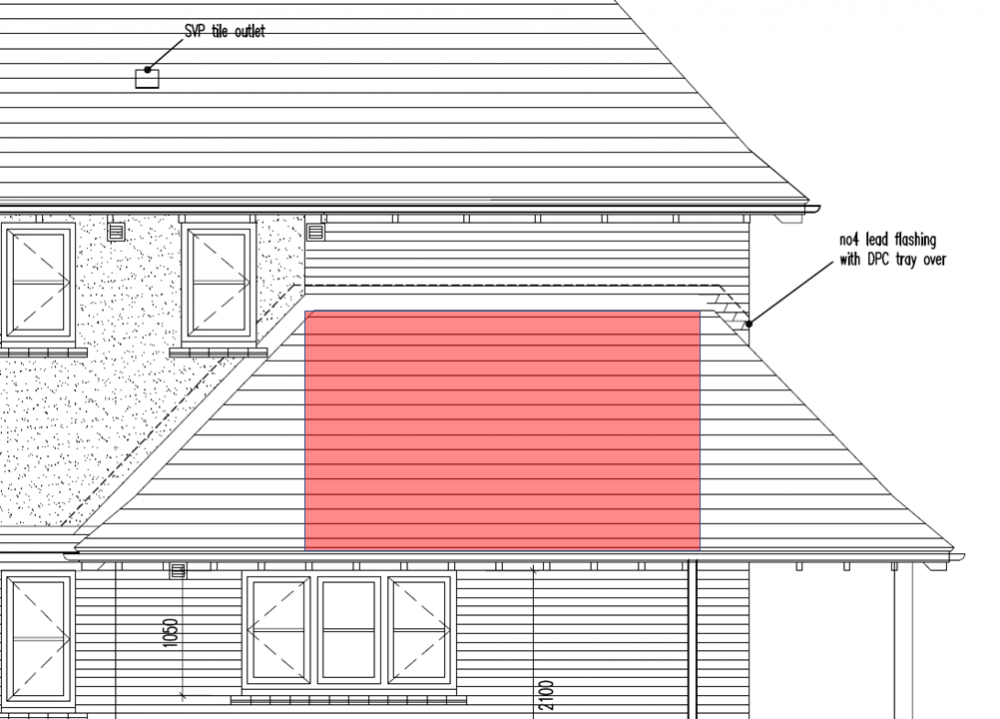
-
Movement Joints between brickwork and blockwork
MortarThePoint replied to MortarThePoint's topic in Brick & Block
Cool thanks. Does that go in at the rendering stage then? A product suggestion would be good as it always helps to see what the finished result looks like. -
Movement Joints between brickwork and blockwork
MortarThePoint replied to MortarThePoint's topic in Brick & Block
That looks really smart @nod , is that some kind of plastic strip either side of mastic? -
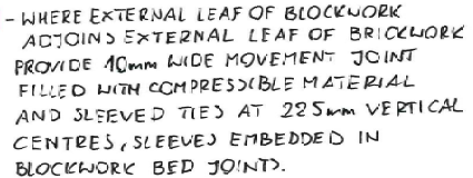
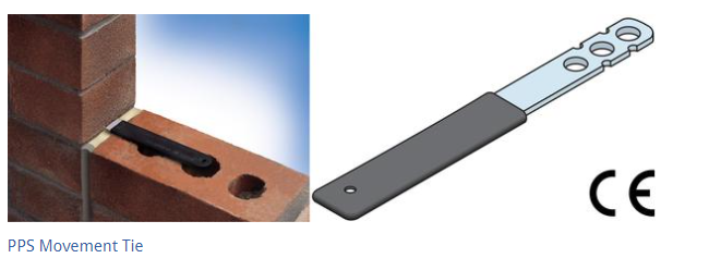
Our design has some brickwork that adjoins rendered blockwork in the same elevation or at corners. The Structural Engineer has called for movement joints here: I presume that calls for the likes of the sleeved tie below, some form of foam strip and then a mastic seal on the outside. If that's correct, can anyone recommend a good foam strip to use (suggestion below) and give any guidance as what to look out for on installation? https://www.buildbase.co.uk/ancon-safetyended-movement-10367-2801192 https://www.buildbase.co.uk/fillcrete-brickfill-100x10mm-10351-2801693
-
Beam on Padstone Bearing
MortarThePoint replied to MortarThePoint's topic in RSJs, Lintels & Steelwork
Thanks, these look great. They look to develop a strength of 40MPa which is 40N/mm2 so close to C50 cement of the padstone and should be runny enough to flow or get pushed in. Wonder if I can get less than a 25kg bag as I'll need less than 1kg. -
Beam on Padstone Bearing
MortarThePoint replied to MortarThePoint's topic in RSJs, Lintels & Steelwork
Runny structural grout sounds interesting. What sort of mix is that or is there a particular product I should look out for? -
Beam on Padstone Bearing
MortarThePoint replied to MortarThePoint's topic in RSJs, Lintels & Steelwork
The challenge is a bed mix involves lifting one end of a 400kg beam. I could use an acrow I suppose. -
Fair enough. As I say I love the look.
-
Beam on Padstone Bearing
MortarThePoint replied to MortarThePoint's topic in RSJs, Lintels & Steelwork
The widths are fine, it's the level and the gap that opens up that I'm wondering about.


