Onoff
-
Posts
21126 -
Joined
-
Last visited
-
Days Won
206
Everything posted by Onoff
-

Simpler stairs: concrete winder
Onoff replied to ToughButterCup's topic in General Construction Issues
Weird stuff. A handful goes a long way in the mix. Can leave the surface a little "hairy". I meant to use the fibres when I did the bathroom slab. This as well as the A142 mesh in there. I forgot the fibres! When it came to do the wet room corner I couldn't find the bag of unused fibres so bought more...then found the first bag. -
Simpler stairs: concrete winder
Onoff replied to ToughButterCup's topic in General Construction Issues
If you do this carefully you could incorporate mat wells on each step or recess features in the side. Line your mould with sheets of glued on DPM and the finish will be like glass. Top step where you pour from might look different..... Ooh...lights. Or infill the "mat wells" with coloured gravel, crushed glass etc and clear resin.... -
Simpler stairs: concrete winder
Onoff replied to ToughButterCup's topic in General Construction Issues
Good idea. Much easier to demolish when you remove the shuttering and it looks sh!t! ? -
Simpler stairs: concrete winder
Onoff replied to ToughButterCup's topic in General Construction Issues
You'll need a poker too to vibrate the concrete into every nook and cranny. Once your ply "mould" is built you can do the internal corners of what will be the step nosings with tooled silicone to give a nice radius. Guessing a 3:2:1 mix using 10mm pea shingle rather than 20mm all in ballast might be better? -
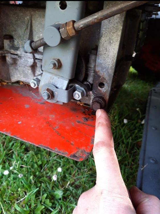
Old gearbox off but I sheared 3 out of the 4 bolts holding it on. I'll drill out and retap. The same bolt positions on the new gearbox drilled a bit bigger and tapped M10. I had to swap the gear change plates over as different lengths. Next I need to swap the pullies over as mine, the more orange, less rusty one has an extra hole for the pto to drive the grass box flails. Remaining wheel still refusing to budge!
-
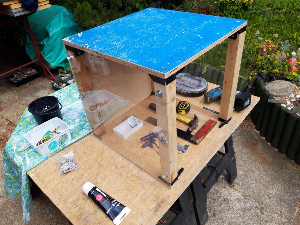
Little by little it's getting there. Blingy lights awaited. Power socket and extract fan to be fitted though the holes are all there. More trim round the front doors etc. Not too shabby for what was scrap timber and free plastic:
-
1/2 acre. Existing house slap bang in the middle.
-
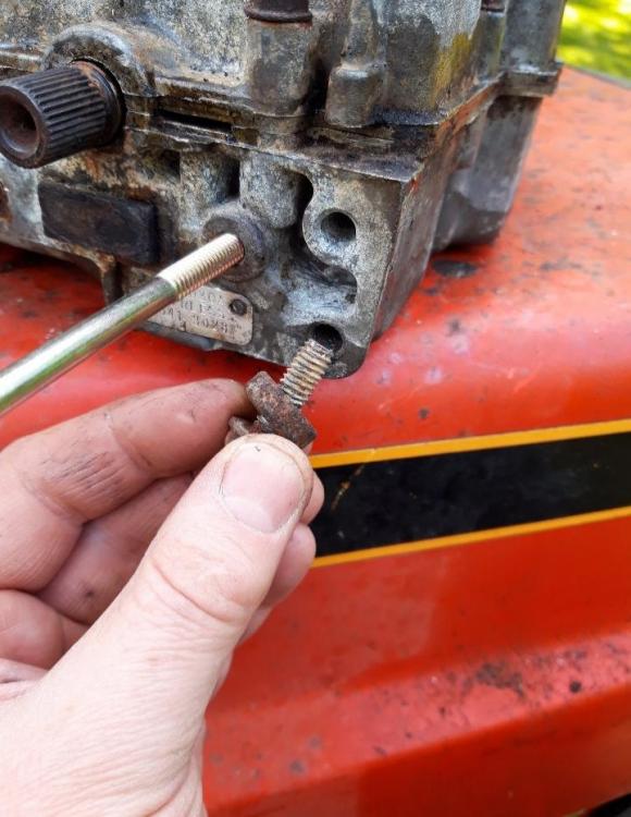
Well this mower is fighting me all the way! Seems that although the gearboxes are the same basic casting, my original one has tapped fixing holes into the ali gearbox. On the donor, the "new", gearbox these are pilot drilled and not tapped as the gearbox attaches a different way. And to boot they're UNC. This is mine. One bolt came out OK. The remaining one feels like it's going to shear. This is the donor, new box, holes need tapping: So this morning, looking at re tapping the bolts into the gearbox. The removed bolt measures 5/16" outside diameter. Teeth per inch is 18. So from my trusty Zeus book that makes it 5/16" BSW or 5/16-18 UNC. This Peerless gearbox being American I'd go for it being UNC. (BSW have 55deg and UNC 60deg thread angles. In the rough and ready circles it's considered acceptable to interchange bolts as all but the 1/2" size interchange from memory. 1/2" BSW is 12tpi, 1/2" UNC is 13tpi. There's other differences in the thread tips are pointed on one and rounded on the other). I only have taps for UNC but likely to be one bolt down anyway if (when) this next one shears. The holes in the gearbox measures up 9/32" as far as I can tell. So 7.32mm in new money. Recommended tapping hole sizes are 6.4/6.5mm for BSW and 6.5/6.6mm for UNC. I'm guessing these holes have grown a bit through corrosion. I'm tempted to drill out the 7.32mm holes to 8.2mm and re tap at M10 metric coarse. Not sure that tapping M8 will be "grippy" enough in there with what's left after the corrosion that's done it's thing. M8 requires a 6.8mm tapping hole and I'm at 7.32mm. Thinking M10 will be a bit "chunkier". Or I get some UNC bolts... Or I use "whatever" and thread lock... I'd rather avoid helicoils. Any thoughts to push me one way or the other? ?
-
UFH pipes?
-
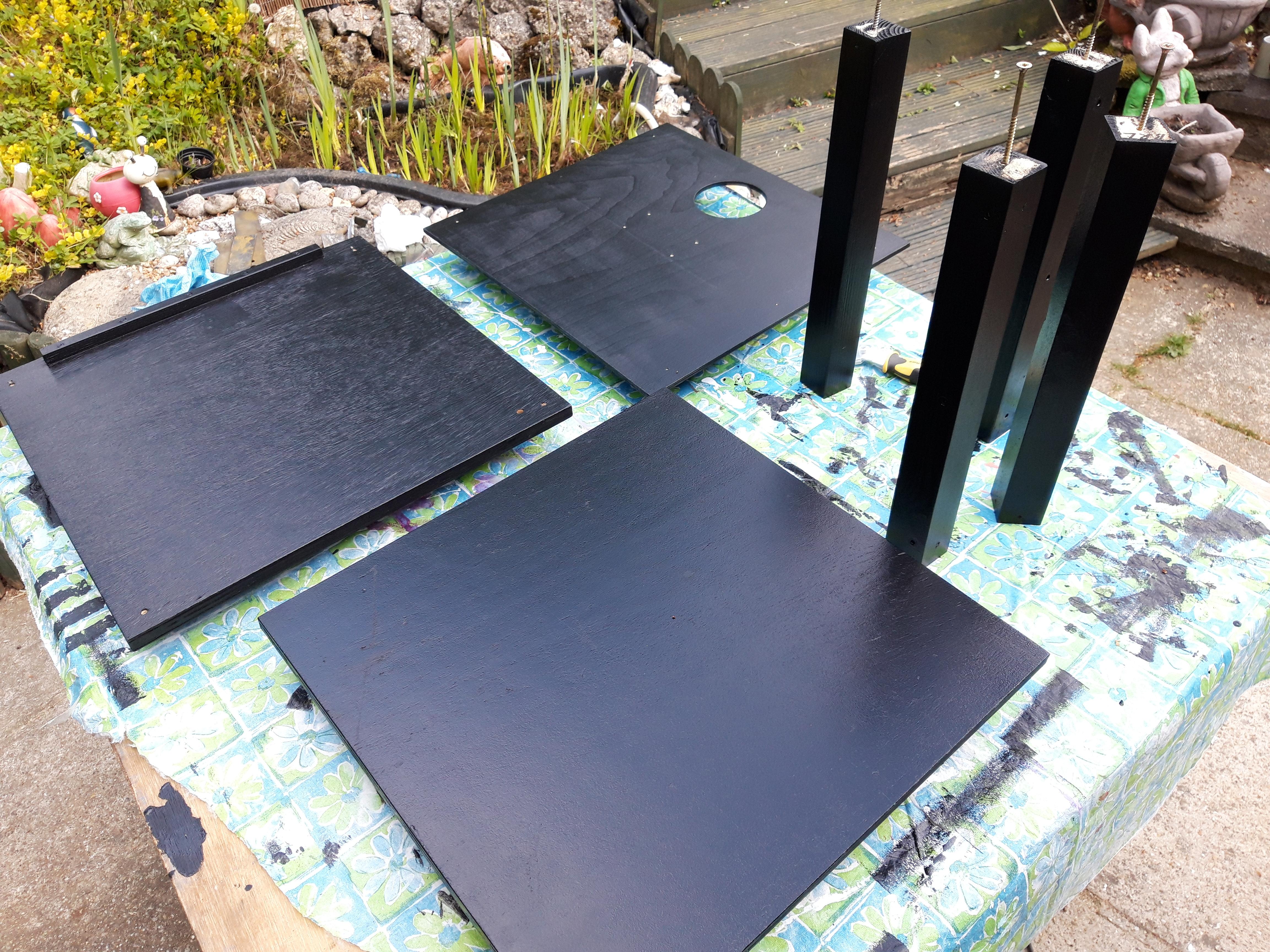
Going for 3 coats of rollered, Bedec, satin black barn paint on the printer enclosure. Hugely expensive at about £50/5l. Got for our front gate originally. Drilled for an extract fan (if needed) and the rear power socket: Re-assembly tomorrow hopefully!

-
I didn't spell it out because on Weds of this week, page 5 of this thread, I said that I thought noggins were required to do with added fire resistance. As the thread was going a bit back and forth I took the time to find why I knew that. Tbh I I've actually heard it as word of mouth, more than once, rather than read it. I'd never heard of the White Book. I found it and posted it. It's there in black and white. For most people, even novices that would have been enough. The end result btw, of what YOU do is cracking. It's just the getting there that's a bit traumatic! ?
-
I had hoped you would pick up on the fire resistance bit. In essence the plaster should fill the gaps that your builder has left reinforced with joint tape. Simply put the joints will not be as secure against fire or hairline cracking as if noggined. Bottom line is you can generally do a better job yourself than many so called professionals. Do what @ProDave says. You have a solution. You could have done it by now.
-
Filling & sanding today hopefully!
-
Thanks. Can you get an Arduino with onboard Wi-fi? Printer might be placed in another room with no ethernet port. CPC for it?
-
When I built a second skin onto our outhouse (should have/could have just done EWI ?) I used 50mm Rockwool cavity batts in a 60mm cavity. I bent a length of 5mm ali flat 50mm wide a 4" return on the end. I lifted all the squeezed through stuff with it. Mind you it was minimal as I used a Bricky tool. Cleanest cavity you'll ever come across!
-
Thank you ever so much...though I haven't got much of a clue of what I'm looking at or how to implement it on the Pi. I last did any programming on a ZX81 then pcs running DOS. Since then, nada! Tbh I was never very good at it then. More hands on, monkey see etc. I keep meaning to learn Python, I at least recognise it as that. A bit like I keep meaning to learn another CAD / modelling package to compliment the hard learnt, now engrained AutoCAD. Maybe Fusion 360 or Solid Edge / Works etc. Old dog etc! The single, off the shelf, digital thermometer isn't really what I want. I want to measure multiple internal points. Print bed temp is known so I want to measure the air space above the print bed maybe at two points. Exhaust temperature is good to know too. It may be that the fan has to be switched in/out to maintain a stable temperature. Likely too some measurement around the printer's mobo and MOSFET boards and maybe it's air intake. So perhaps measurement at 4 points, perhaps 5 with ambient also. I've heard my lad teaching a mate Python during lockdown of late, maybe he can teach me. I presume I just add in code for multiple sensors? How do you know the sensor number, the "28..."? Is there a sensor good up to say 150degC? And WHY in Python don't you have line numbers like you did in MSBASIC? 1 IF 2 GOTO 3 LIST Etc Cheers
-
@SteamyTea, @ProDave, etc. I'm after having a real time temperature monitoring system for the 3D printer enclosure. I know what I'd like but have no idea if its possible! - Wi-fi enabled Raspberry Pi - DS18b20 sensors My lad I'm sure can figure that bit out. - GUI on the pc. Ideally a simple graphical representation of the enclosure with the various temperatures. That's the tricky bit for me. Any pointers/links/guides? My lad just said "Why not use a list?" and went back to gaming. He's happy though reading pages of code like mere mortals like me look at pictures! Aside I think these sensors are only good up to 105degC. https://www.circuitbasics.com/raspberry-pi-ds18b20-temperature-sensor-tutorial/ Cheers
-
Yes, for ABS, bed at around 110degC. They reckon even with fan exhaust the internal enclosure temperature can reach 45degC.
-
Not really. I used the forum search function. Typed in "zoot osb pir" and put you as the author. A quick scroll through the pages that came up and I came across your thread:

-
Page 19 here:
-
Go ask in the architectural section on the mig welding forum. Might find someone local to you. https://www.mig-welding.co.uk/forum/forums/architectural.61/
-
Presumably when you fid your extension it was done properly and somewhere along the line someone considered thd structural engineering implications. Surely your neighbour should be having any such calcs before the build is done rather than throwing it up ad hoc and only then will the council get involved?
-
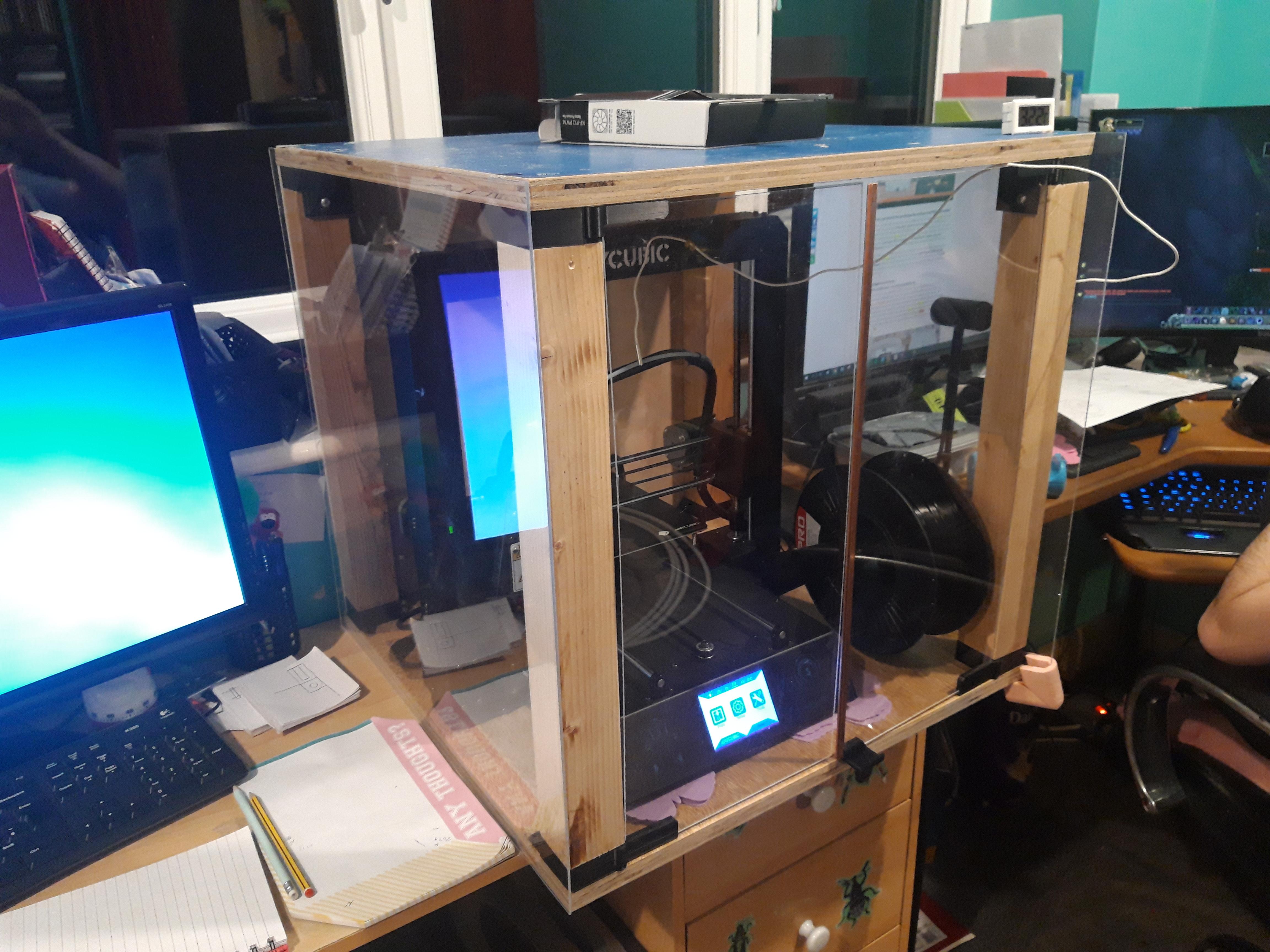
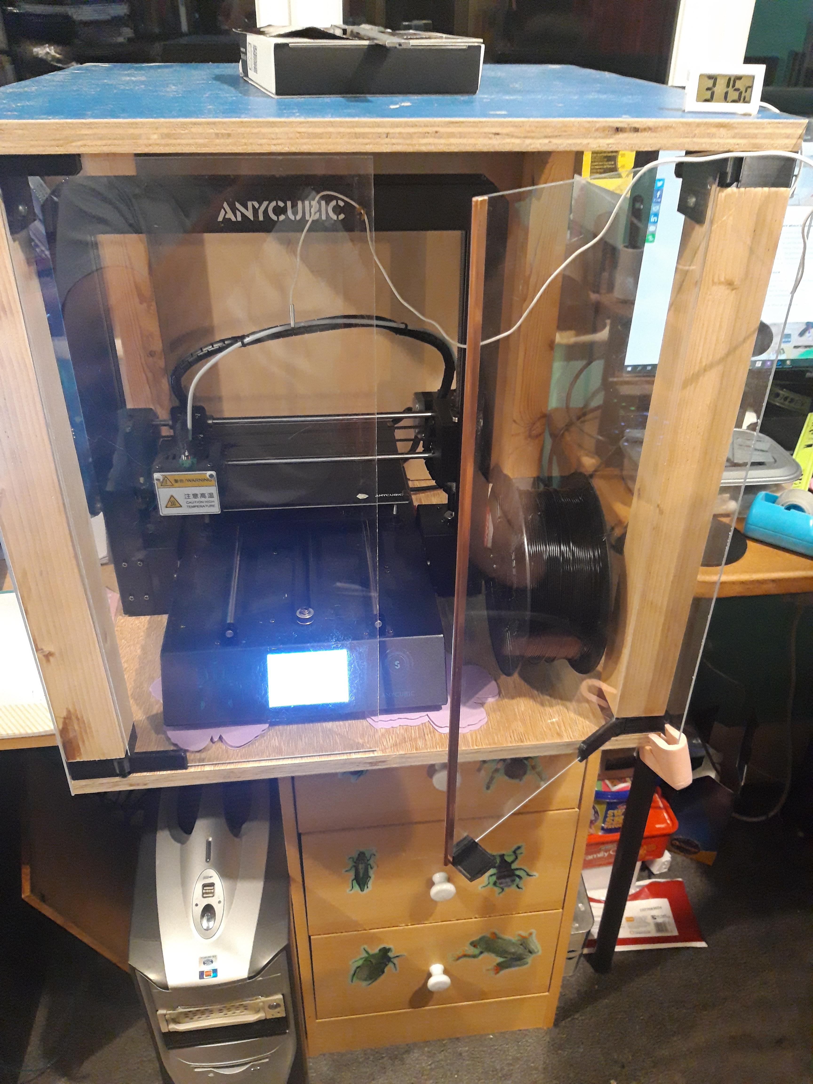
A bit more progress. Though you can't see them the reprinted bits are done. All joints slackened and re tightened for a better fit. Two front doors cut to size from 2mm perspex or whatever this freebie stuff is. As I feared 2mm is a bit flexible so on one door I've clipped a length of copper bus bar that fits over the edge a treat. Makes things much more rigid. Sides just stuck on with Sellotape at the mo. As a little test ran the bed up to 40degC. Using a little remote thermometer the internal temperature held at around 38degC. On the face of it that's good but when you think for ABS it needs a bed temp of like 110degC that will not be at all good for the printer's internal electronics; the psu, MOSFET board etc. Looking now to move these parts outside the enclosure. Got some blingy, wi-fi controlled, USB powered LED light strips coming for the inside. Comes with remote and can be controlled via an app. Picking up a 2G, MK USB socket to go on the back later.


-
I'd take the extension down or move the party wall in to my side and erect a rickety fence. Just to f*** him up.
-
For "bulk" filling I've occasionally cut a chunk of Celcon block with a saw and stuck it in with No Nails etc.