


Onoff
-
Posts
21125 -
Joined
-
Last visited
-
Days Won
206
Everything posted by Onoff
-
This comes up a lot. Have a good read here:
-

Discount Offers of the Week
Onoff replied to Ferdinand's topic in General Self Build & DIY Discussion
Dymo labeller at Aldi: https://www.aldi.co.uk/dymo-labelmaker/p/803497428917600? Ideal for making grid switches look dog rough! ? -
Illbruck is a name to conjure with. Really good stuff. They do airtight expanding foam and tape too similar to Compriband. <£10 a tin to go in a foam gun. A couple of quid cheaper you have Everbuild acoustic/airtight foam. We have a "window" man on here, can't recall his name, Craig?
-
The Self-Build-But strikes again: this time lights switches,
Onoff replied to ToughButterCup's topic in Lighting
I nearly bought my lad a laser engraving add on head for his 3D printer at Christmas. I couldn't for the life of me think what to use it for at the time! I was thinking wood/leather. Saying that I'm not too sure how plastic will fare with the laser... -
The Self-Build-But strikes again: this time lights switches,
Onoff replied to ToughButterCup's topic in Lighting
A bit late now but... ...you can always mount the grid horizontal and have the writing in line with the switch action. Saves you getting a stiff neck! ? -
The Self-Build-But strikes again: this time lights switches,
Onoff replied to ToughButterCup's topic in Lighting
& another place: https://www.laser-techniques.com/switch-plates-electrical-accessories I think that Schneider themselves offer the service. Certainly do for the control gear legends I buy. I will ask my man! -
The Self-Build-But strikes again: this time lights switches,
Onoff replied to ToughButterCup's topic in Lighting
Change the grid plate to a metal one and get it custom engraved & colour filled? Tbh I think they engrave / fill plastic too: http://able-engraving.co.uk/engraved-products/grid-and-switch-plates/ -
I see I used Sikaflex on the sink waste. Tbh think I did on the bath too:
-
Exactly where is it leaking? Around the black nut or where the white waste screws on?
-
I'd do away with the washer on top, they tend to be a bit generic, one size squashes to fit "all". I'd put a big slug of BT1 etc around the waste. Similar principle to how I did my bath waste. Ditched the top washer, kept the one underneath. The top, baby wiped to finish: Same on the washer underneath: Tighten but do not let the top turn even if it means SWMBO standing above. You want to compress rather than "smear" which will kick it all out of the joint (so @Nickfromwales said).
-
Heatmiser Neostat v2 temperature sensor problem
Onoff replied to Ultima357's topic in Underfloor Heating
How cheap do you want, any good? [£23.28]MK72GA Smart Water Heating Thermostat WIFI LCD Touch Screen Temperature Control Regulator for Water Heating System Measurement & Analysis Instruments from Tools on banggood https://banggood.app.link/m5kUTOr88cb -
Decent foam, done right? is alright. Compriband BEFORE the windows/doors go in is better. Is it all going to be airtight taped?
-
Why can't you spin the U bend round so it faces the waste pipe then reduce there? Is it all solvent weld at the back?
-
You do like to make things hard for yourself.
-
The boxing in up by the ceiling, is there a pipe/drain behind that?
-
The 4th picture of the opening post appears to indicate something boxed in. Could that be "pipes" where a joint has failed?
-
You might find some useful comments here:
-
Sips panels and rendering
Onoff replied to Russell griffiths's topic in General Self Build & DIY Discussion
They're wrong but you're still a lunatic! ? -
Ground floor shower tray - concrete slab headache.
Onoff replied to SuperJohnG's topic in Waste & Sewerage
Though I cast my shower corner floor to falls for a wet room corner, I did the main slab, with mesh in first. I just shuttered off the for the shower corner (and part sunken bath): I did though remove the red Polypipe panel in this area to get a consistently thicker, stronger slab. What a mission that was cutting it up in bits. Similar fun was had then fitting a bit of DPM with the mesh in situ! My SBR heavy, 10mm pea shingle, concrete mix: A few on here have just left in a bit of EPS level with the FFL that you dig out later. You can decide on your trap position later. -
Heatmiser Neostat v2 temperature sensor problem
Onoff replied to Ultima357's topic in Underfloor Heating
The instructions say to mount at eye level and in a 35mm back box.- 150 replies
-
- 1
-

-
- neostat
- temperature
- (and 1 more)
-
Same old same old. Improve your property, increase the value and cop even more tax.
-
Query on if this is right - Loft Insulation
Onoff replied to canalsiderenovation's topic in Heat Insulation
Have a look at the some of the images here. The "arrows" represent the airflow you want to wick away moisture. https://www.google.com/search?q=eaves+ventilation+airflow&tbm=isch&ved=2ahUKEwjE0a7Yl6PuAhVP_4UKHbviC_YQ2-cCegQIABAC&oq=eaves+ventilation+airflow&gs_lcp=ChJtb2JpbGUtZ3dzLXdpei1pbWcQAzoECCMQJzoCCAA6BAgAEB46BAgeEApQpU1Y1F9g8GdoAHAAeACAAXWIAYUHkgEDNS40mAEAoAEBwAEB&sclient=mobile-gws-wiz-img&ei=lUoEYISzDs_-lwS7xa-wDw&bih=512&biw=360&client=ms-android-motorola&prmd=simvn This grabbed from a US site: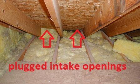
-
Query on if this is right - Loft Insulation
Onoff replied to canalsiderenovation's topic in Heat Insulation
@canalsiderenovation, out of interest do you have ridge ventilation too? As an aside sometimes the loft insulation can be pushed too far into the eaves and that prevents the ventilation getting up past it to the underside of the roof. -
Grain soaked in whiskey, an old poachers trick for pheasant. I bet crows are sensible enough to drink in moderation mind! Or scatter raisins on the roof and cover with a sheet of glass. They'll knock themselves out trying to peck through it... ?
-
Obtaining Copies of Building Regs Documents
Onoff replied to Ferdinand's topic in Building Regulations
I don't know if each LA has it's own rules but I got the drawings for our place, extended and reroofed in the late 1980s just by asking nicely about 4 years ago. Got paper copies, foc, taken from a microfiche. Tbh the quality isn't all that. I did thereafter ask for a scanned file that I could blow up myself. Although promised over the phone it never materialised. They were hand drawn planning drawings but have all the timber and steel sizes on. They reference "supporting calculations" which I couldn't get unfortunately. Until you ask etc. Don't forget many are working from home so something like digging through microfiche archives might not be seen as a priority.- 5 replies
-
- 1
-
-
- building regulations
- foi
- (and 1 more)

