

Radian
-
Posts
2586 -
Joined
-
Last visited
-
Days Won
15
Everything posted by Radian
-
Interesting. Free is hard to pass up on. As for how to use them I can't see how you could really do it without some practical electronics knowledge. Like ProDave says, it's not so much a job for a sparks as for an electronics engineer. Doubtless there are a few who fit both descriptions but I don't know how you'd find one. Basically you would need a way to charge the batteries - wired in a series string to match the output of your PV array. But that could be several hundred volts so you might not have enough batteries. But if you did then you would need a way to limit both the charge current and final voltage. If such a system were in place then it could be as simple as a couple of Silicon Carbide Schottky Diodes to merge the battery bank with the PV array to continue powering the invertor after the sun has set. The annoying thing (for you I imagine) is that everything could be done with simple switches and a multimeter plus a couple of diodes all for under £20 but you would be the guy in charge of the switches!
-
The SAS should give a job to these mice. I googled can mice climb walls and watched some of the videos. Our Purbeck stone elevations offer numerous easy routes up to the roof. This is my actual house where the two roofs meet...
-
The trouble with having the pump controller permanently powered is that it will tend to run when the main system pump/valves are off. This can do odd things like drain heat out of your DHW via the indirect coil. In other words it will tend to form its own weird circulation path. I have a similar setup so ended up wiring the UFH pump control box in parallel with the main circulating pump.
-
Are you talking about this Jerry?

-
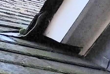
Funny you should mention that. I found a pack of SS pan scourers in the workshop today and wondered if they might bung the gaps. I can picture the mice pulling them out though so I' was thinking of applying some acrylic caulk to the edges of the opening to glue them in place. But on closer inspection, the lead valley above gives shelter to these areas so I'm not even sure it's necessary to worry about filling the gaps entirely with caulk. It's not like there would be torrents of water flowing past under there.
-
Once again the series resistance will have the effect of reducing the power to the loads. There will be some heat generated in the poor connections but it will not make up the losses in the loads. Overall the grid will supply less power. There are certain kinds of loads that would be an exception however, those that regulate for the required power in the load. Examples would be digital electronics like PC's, TV's and some, but not all, LED lamps. It's funny to think that all the loose connections in a house (and overloaded wiring) contribute to the domestic heating (by a miniscule amount of course) so will reduce the demand for heating fuel. It's like how LED bulbs now contribute around 1/10th the heat that their incandescent forebears used to provide so our heating bills have gone up in the drive to save energy. The offset is still worthwhile it to the consumer given that energy for heating tends to be supplied at a lower cost but from a global energy supply perspective there is much less of a distinction.
-
You mean it shifted all those stones into it? Why I wonder - was it trying to protect its mates?
-
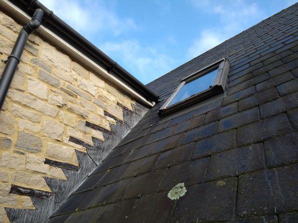
Having trapped the mouse on the 6th of January, we now have another one running around in the attic less than two weeks later. After we got rid of the previous one I spent the day going around the perimeter of the house looking for entrances. There was nothing. But at head height, the sloping roof of our lean-to utility room had about 1cm gap between the eaves vent and the stonework of the house. This could have gotten a mouse into the soffit box, up the outside of the insulation panels and into the second attic. A generous squirt of acrylic sealant sorted that gap. But this new mouse definitely didn't get in that way. The acrylic plug is still intact. As is the squirty foam filling I did in the main attic at the valley junction between the two roofs. Just to explain, the two roofs create two attics because indoors, the two halves of the house are separated by a double-height hallway that goes all the way up to the ridge. The steel beams supporting the ridge and wall plates, however, form three tunnels linking the two attics. Handy for wiring but also highways for vermin. The problem now is that there are a couple of obvious entrances either side of this dormer window: This is the same kind of problem where the soffit stopped at the junction between roofs. I could get at that junction from inside the attic to block it but this dormer isn't as accesible. I can't see inside and around the corner to this gap. So I'm not sure how to close it from the inside or the outside. I don't want anything to bridge between the slate and wooden fascia.

-
I recently bought a used 180W dehumidifier off gumtree for my woodworking shop. It adds about one degree C to ambient but in combination with the drop in humidity makes it feel much more comfortable. I think it's an all-round great idea. I would say go for around 300W if you can find one - then it's doing some useful work while providing some heat. The only problem is that you do really need at least 10°C in the space around it for it to dehumidify efficiently. The point is, you could heat with just a resistive element but then again, raising the temperature is all it does. Because nearly all the energy going into the dehumidifier ends up as heat you get rid of some water vapour as well as providing some heat into the bargain. It all aids in lowering the dew point. After I put in a 2kW convector to heat my electronics workshop I realised it might have been better to offer the place as a home for bitcoin mining. Getting useful work done with the energy that's being consumed and turned into heat is a more effective use of electricity. If anyone wants to split the electricity bill, I'll host their rigs (up to 2kW) ?
-
There's always a smart arse, and today it's my turn! In the interests of there being no false information on the internet, I have to mention that the current won't increase as a consequence of using a long extension lead. It will be reduced. What has been assumed is that the power will remain constant. It won't, not for dumb resistive loads like these heaters. At 240V this total resistance looks like V/I or 240/16.66 = 14.4 Ohms. This resistance will remain constant, so at 220V the current would drop to 220/14.4 = 15.27A and the power would drop to 220x15.27 = 3361W Of course we would have to take into account the resistance of the cable that's causing the 20 volt drop, something like 20/15 = 1.33 Ohms and this would dissipate 300W of its own which is the real reason this would be a very bad idea! I hate myself now.
-
Yet is surprisingly common ?
-
Was actually thinking more of diamond disc cutter than bashing with chisel but I understand if you feel that might be too disruptive.
-

HELP Vaillant Boiler not working - URGENT
Radian replied to Adsibob's topic in Boilers & Hot Water Tanks
Probably just needs air bleeding. Must have been drained down to replace divertor valve. Some naughty air still hiding in primary somewhere. -
Construction companies failing
Radian replied to Temp's topic in General Self Build & DIY Discussion
Why on earth would you want one of them?? -
Like PeterW, I'm thinking it might be that the return path from DHW coil is finding it easier to go via a couple of radiators & their returns back to the boiler than the intended path. This could show up as one of the radiators having a hotter return pipe than its feed. I can't be arsed to draw a picture but in words: the DHW return meets a radiator return where they're both on their way back to boiler. This rad would be the one with a hotter return than feed. Its feed connects to the same feed as another radiator, which has a less restrictive return to the boiler. This circuit is then hot when it shouldn't be.
-
So when they're 'being naughty' you're saying the feed is hotter than the return, and the same is also true when they're 'behaving'?
-
What's to stop you cutting some of the rubble back to square it up and create enough space for a decent thickness insulation backed plasterboard circa 40mm?
-
Probably fitted with TRV's - is pipe going into the TRV hotter or cooler than the other side when radiators shouldn't be on (trying to figure out flow direction)
-
What are your plans for the ceiling insulation? Post up a photo of the underside of the OSB as it is now...
-
SBR has gotten me out of quite a few sticky situations ? You just know it's good because it's reassuringly expensive!
-
@Onoff have you thought about brushing a cement/SBR slurry on the backs of those flints? I don't know if that would get you the adhesion you need but it works on shiny stuff like porcelain.
-
Other people will probably shoot me down but I favour the lightweight backers such as these But I'm getting weak in me old age and can't lift the solid ones ? Do need plenty of support though! (the backers that is... for now).
-
From my experience, any tiled wet area will present damp to the substrate after at most 10 years or so. I believe grout is slightly permeable and ceramic certainly so once microscopic cracks appear in the glaze. Which they will. For complete peace of mind use a waterproof backer.
-
Surely there's no point at all in spraying foam in what will remain a cold roof loft? The intention must be to convert it into an unventilated, warm roof. If the house was constructed with a warm roof at the outset then, as you point out, a surveyor couldn't inspect the condition of the roof covering from the inside anyway. So what nonsense is it then to deter the conversion of a cold roof into a warm roof on the grounds that it couldn't be inspected alone? However I think it's not entirely trivial to analyse the outcome of such a conversion... In a modern attic room with a cold roof, insulation is typically located between the rafters in addition to a continuous layer on the back of the rafters to ameliorate cold bridging. A vapour barrier is then required on the inside between the insulation and internal finish e.g. plasterboard with a foil backing. so far so good as all this can all be done as a retrofit. But the wind control layer under the outside roof finish always seems to be specified as vapour permeable (to provide ventilation for the timber rafters) and the insulation would be prevented from going all the way to the outer face of the rafters to promote air circulation for the timbers. This, I understand, is standard practice for a cold roof attic room. So this is where I get a bit lost with the closed cell spray foam because if the original wind control layer was a vapour barrier (Bituminous roofing felt, sarking etc) then the rafters should not be subject to water vapour at all and, I guess, would be fully sealed (my instincts tell me this is bad though). The build-up on the outside of the wind control layer is no different to before the conversion so that's fine. The back of the rafters on the inside would still be a cold bridge but for the fact that the spray foam covers them completely so that should be OK as well. I personally wouldn't want there to be a void between rafters (given that the foam will not fill the space entirely) so I would fill with rockwool or similar - even though the void should remain warm and dry. Seems like the application of closed cell spray foam should be OK then ? ?
-
I'm not so sure. Most pre 21st century houses have Bituminous roofing felt which doesn't breath so without crossflow there's scope for rot. But I wasn't thinking so much of the rafters above but the attic floor/ceiling below. A house worth of water vapour is waiting underneath and a fully foiled-up attic suddenly becomes unventilated for the first time in the houses history - unless a deliberate Vapour barrier exists at ceiling level. Again, ventilated attics never had such a fitment. IMO, Interstitial condensation is not something your typical Aldi customer has at the forefront of their mind.

