
Radian
-
Posts
2586 -
Joined
-
Last visited
-
Days Won
15
Everything posted by Radian
-
When we got PV on our outbuilding and I asked about batteries in the same building the installer insisted that we could only do it with an AC battery that had to be within a few meters of the utility meter in the house. This was because of not having any way of connecting a current clamp from the outbuilding to the incoming mains. A cat 6 cable might suffice. Or perhaps make it a 4-core SWA to hedge your bets.
-

Calculating for the use of sand for a thermal store.
Radian replied to Marvin's topic in Boffin's Corner
That'll teach me to do sums when still hung over! -
Calculating for the use of sand for a thermal store.
Radian replied to Marvin's topic in Boffin's Corner
When it comes to lossless energy storage you can't do much better than bunch of rocks minding their own business. It takes approx. 50,000 Joules to lift 1000 kg 5 meters (roughly 14kWh) so around 35 tons to see you through the winter. -
Well at least you know to look for a hob that uses a half-bridge series-resonant converter rather than a single ended one. Had fun reading the datasheets thanks!
-
The change in frequency must be above resonance rather than below as the inductor's impedance = 2πƒL otherwise the impedance would drop and the whole thing would draw more power at the same time as reducing the cooking power. The switching losses in the IGBT switches increase with increases in drive signal frequency. This means there's a sweet-spot for the operating frequency. I'm a little surprised they even bother with FM - it can't maintain optimum power transfer efficiency over a very wide range. I guess the problem with low frequency PWM is the effect of visible flicker from lighting circuits as the 10's of Amps being gated might produce a significant volt-drop. So it's a trade off between efficiency and controllability. Lower power induction loops might be resorting to low frequency PWM if their switching currents are low enough. Mark-spacing the HF drive waveform with PWM can maintain resonance but still entails an efficiency hit as the switching rise-times become a greater proportion of the dwell time. I guess I'm so used to designing just for maximum power transfer that I'm not that familiar with techniques used to modulate it for cooking.
-
Mouser is approaching his 40th birthday. I kid you not.
-
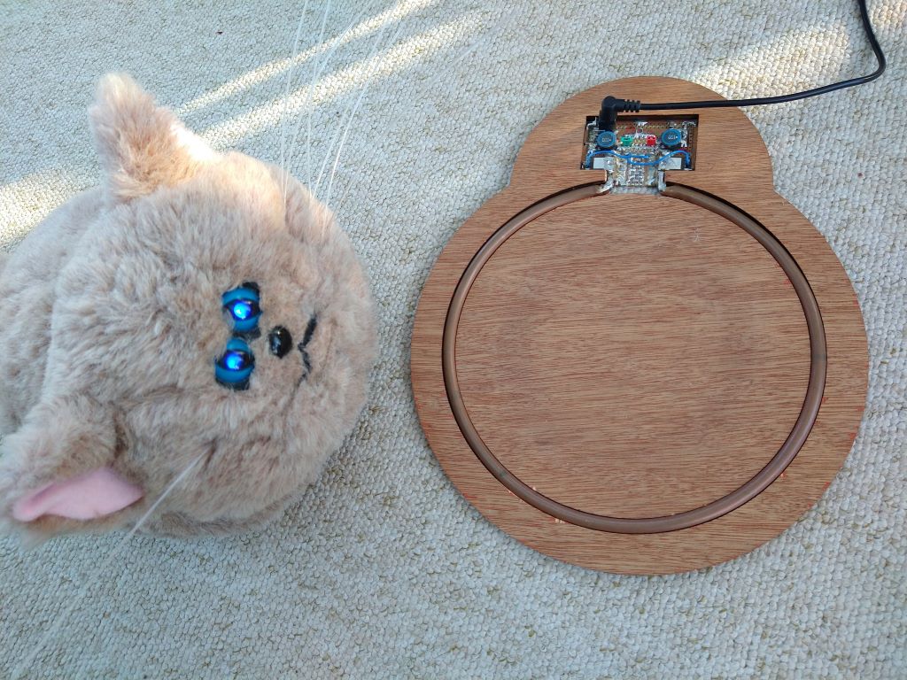
Wow, this has gone some way off topic! Yes. The resonant frequency is always kept above audio frequencies - usually somewhere between 25kHz and 60kHz. I made a wireless power transfer system to charge our robot cat (he just drives on and off a flat plate) but that's running at over 1mHz. At such high frequencies the inductive reactance of that single loop of copper tube is not a short circuit but allows around 10W of power transfer from a 12V 1A power supply. 10 second update? How about 0.02s 😁 That's a GIF of my real-time monitor for my DIY PV diverter. Every vertical slice is a mains cycle. The little blue triangle at the bottom is ~450 Joules going in and out of the virtual buffer in the utility meter. The magenta dots are +/- Watts going through the meter (a few cycles with a 2kW dump load going either on or off). Average watts (as billed for) is the green trace kept just below the zero line. The black dashed horizontal zero line marks 1 second intervals. The dashed vertical line that appears now and then is when the utility meter LED blinks.

-
No written languages are good at capturing techie stuff like this. We have multiple different frequencies to consider - one is turning on and off the mains current in an inductor at a higher frequency than the mains itself, this will have to be a fixed frequency to get resonance. Then this needs to be turned on and off to effect power control. Changing the drive frequency into the resonance circuit would modulate the cooking power but way too much energy would be dissipated in the drive circuit. I think the main difference comes down to how the temperature is monitored for feedback. Cheaper slower hobs probably have less sophisticated sensing.
-
For cost-effectiveness most hobs use a Single Ended Parallel Resonant Inverter to generate the EM field. It's generally optimised for a fixed frequency (resonance) somewhere above audible range. To modulate the heating effect this HF signal is then gated with a lower frequency PWM signal. Because it's all solid state control this can still be cycled on and of quite fast to effect a linear control using the shorter time constants of metal cookware. The difference between cheaper and more expensive models seems to be just how high this PWM frequency is?
-
Unless developed by an online community on github - like OpenSCAD and KiCad etc.
-
Parametric CAD might suit you then. Often I start with a bunch of dimensions and think of the part I want in a simple modular fashion. This is when I reach for OpenSCAD.
-
Had one of these since 2017 Had a few drops and it's still working accurately. Bit on the beepy side at times but you get used to it.

-
Might Solcast be of use to you?
-
I always like to see a spot of Frenching

-
Can you write code, as in program in C or similar? For some applications OpenSCAD can be more intuitive for coders.
-
Radiators or underfloor heating large space
Radian replied to Skithepowder's topic in General Plumbing
On its own a reel of PEX is really not all that expensive. My outlook on this was 'get it down before the screed goes in' and it's there if we want it. I also put a 100m loop in our garage extension play-room or whatever to call it but that's possibly never going to be used now as gas is triple the price it was and we've gone for A2A instead. But who knows what the future holds for energy prices. When A2W equipment prices come down to the equivalent of A2A then the sums might swing back in its favour. -
Radiators or underfloor heating large space
Radian replied to Skithepowder's topic in General Plumbing
I had a last minute change of plan and put a UFH loop in our garden room the day before the screed went in. It's only 18m2 and with block & beam floor topped with 100mm PIR and 50mm screed but was a now or never decision that I'm glad I made. Yes it would be better with 150mm PIR but on the rare occasions when it's below 10oC down here I can choose not to use it. Or pay a few extra quid to enjoy the close-up view of the snow (not that we get that either). -
Update on Energy Use Based on 4 years of Actuals
Radian commented on TerryE's blog entry in The House at the Bottom of the Garden
Since we came out of summer and keep the kitchen at around 19oC it uses even less, just 7W on average. Even the freezers are doing sort of OK at 77W for the pair. Considering that the old fridge was averaging 70W costing £200/year to run and this one is one-tenth of that, it will have paid for itself in less than 5 years. -
Which set point are they talking about?
Radian replied to Radian's topic in Boilers & Hot Water Tanks
Thanks for a really interesting reply! I thought that the June update to Part L brought boiler replacements in line with the requirements for new installations, but... "5.10 Where a wet heating system is either: a. newly installed b. fully replaced in an existing building, including the heating appliance, emitters and associated pipework all parts of the system including pipework and emitters should be sized to allow the space heating system to operate effectively and in a manner that meets the heating needs of the dwelling, at a maximum flow temperature of 55°C or lower. Where it is not feasible to install a space heating system that can operate at this temperature (e.g. where there is insufficient space for larger radiators, or the existing distribution system is provided with higher temperature heat from a low carbon district heat network), the space heating system should be designed to the lowest design temperature possible that will still meet the heating needs of the dwelling." ...on reading it again, it might only seem to apply if you were changing all (?) the radiators and pipework as well. Damn vague as you might expect from something with legal bindings. Leave one short length of original pipe and you can do what else you like.🙄 -
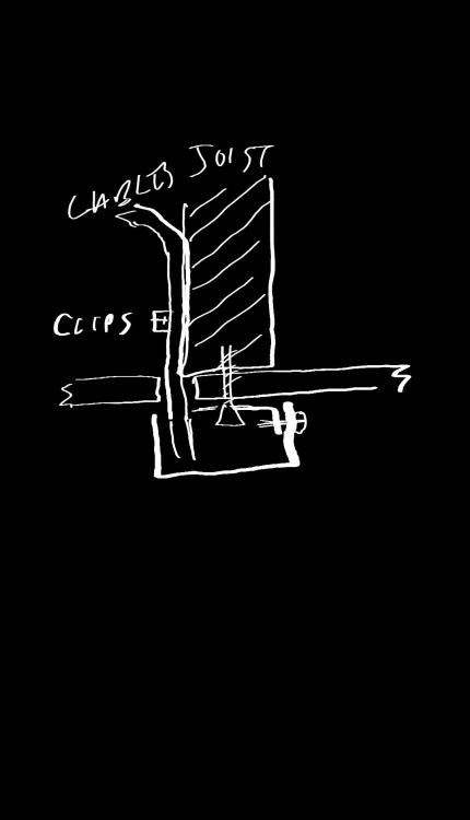
Yes, a good suggestion for an entirely different approach. I would personally prefer using a black trunking surface box and a short length of round trunking to link across but the committee didn't like either option. Gotcha. So the joist supports one part of the cut out piece when I go to screw it back in place. Yes, that's also a good suggestion. I'm now in the awkward position of actually having to choose between all these ideas!
-
It looks like I either have to: cut a hole big enough to get a junction box or crimps through the plasterboard and fish a new cable over to the fitting from there. cut a narrow slot (the width of the cables) along the edge of the joist and push the cables across to the new location. The first option means fixing the cut-out piece back in place (after fixing a support batten straddling the hole) and the cut out piece already has a big hole in it so it will be quite fragile. Ironically I was going to use downlighters instead of the pendant but when I found the original pattress was screwed to a joist I gave up on that idea. On reflection, I could have installed simple can-less downlight frames close to the edge of the joist and possibly even lost the cable hole under the downlight flange. The second option requires a 20cm long slot but it's only 5mm wide so should be easy enough to fill without having to reposition any plasterboard pieces. Also, the cables can terminate in the light fittings connector block as they do now. It does mean I have to get lucky and have enough slack cable to reach over though.
-
That was my first idea too but it was rejected by the committee 😑
-
You mean just enlarge the current hole by enough to get the three cables plus a new one (for the light fitting) up above the plasterboard? If I could pull the cables down far enough to strip more of the outer sheath and work with individual wires I might be able to use twist connectors to join them and push them through one at time I suppose. I think that Wagos would be too bulky.
-
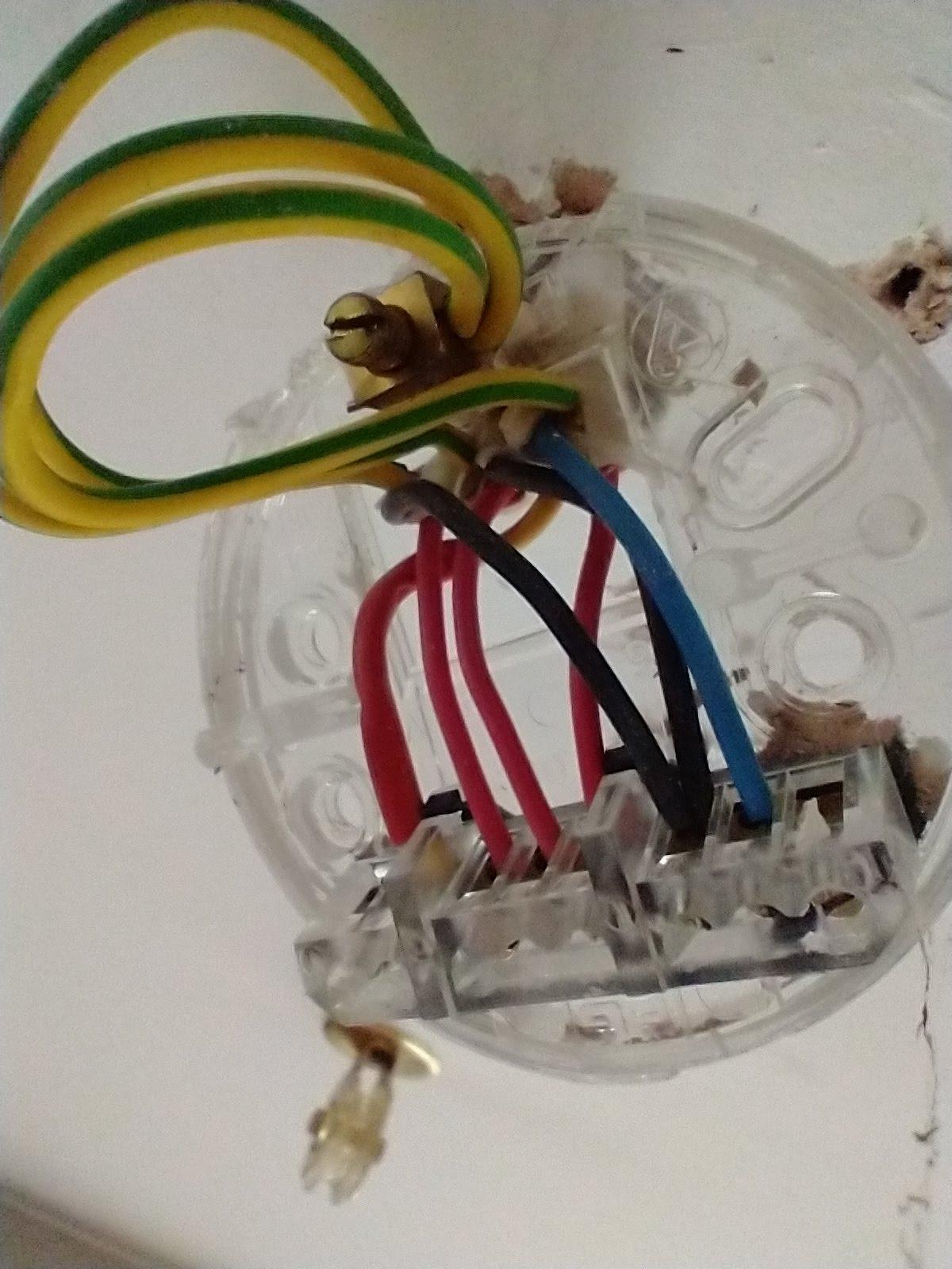
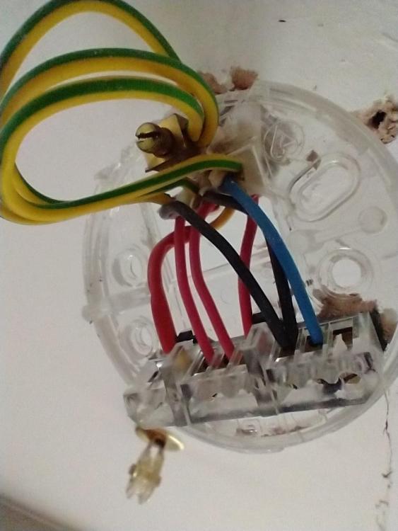
Oh yeah, I forgot, I took a photo before I started:
-
The long black box runs parallel to the joist and is barely wider than it (about 57mm wide on a 47mm joist): Of the three cables, one is 4-way with a red sleeved "switched live" to this fitting, and three other sets of lives neutrals and CPC's are connected in parallel.