
Radian
-
Posts
2586 -
Joined
-
Last visited
-
Days Won
15
Everything posted by Radian
-
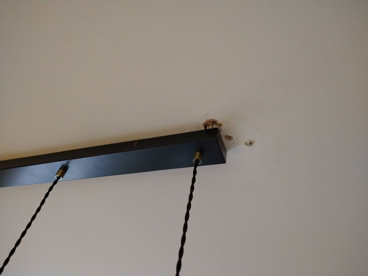
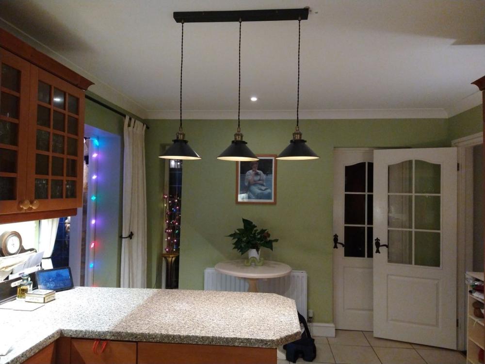
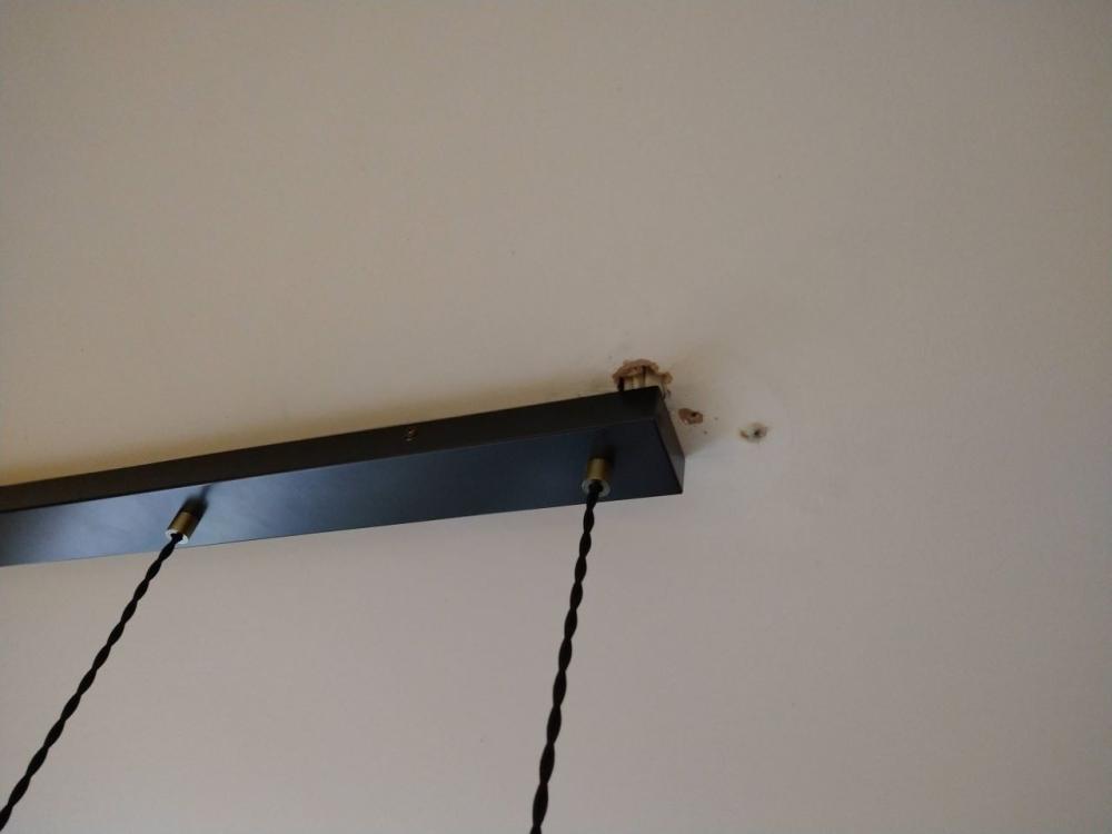
Our kitchen had a single pendant drop at the far end of a peninsular worktop which never really lit the surface very well so we recently bought a triple pendant unit which works better but having just fixed it to the ceiling as far over as possible (as determined by the cable position) it's still not sat entirely over the worktop: It needs to be about 20cm to the left. Here's a close-up of the end where the cables come out the ceiling (originally into a pendant light pattress hence all the holes that need filling) and these cables are the reason I couldn't get it any further over: There's a floor joist directly above the black metal case of the pendant unit (ideal from the point of view of fixing it to the ceiling) and I can just see that the cables for the original light pendant are clipped to the side of the joist immediately above where they come through. Ideally I would access all the wiring from above and just move it over to a new hole but the room above has fitted furniture which makes this impossible without doing some major deconstruction. I'm not quite sure how to proceed. I don't want to enlarge the existing hole for the cables any more than I have to as it will all need filling. I don't know how much spare cable there is either. I can cut a new hole for the cable drop further along but again, I don't want to make the new hole too big as it's right out at the edge of the metal box. It's also a pain that there are three cables to terminate as the live and neutral is looped out to other ceiling lights. I'm not sure my luck would hold out if I pushed them all up into the ceiling void and tried to pull them back out again through another hole. Anyone got any bright ideas?
-

Which set point are they talking about?
Radian replied to Radian's topic in Boilers & Hot Water Tanks
I say its a mess because the motive for ensuring heating systems are ready for heat pumps is all fine and sensible. But in Europe, manufacturers are legally obliged to provide equipment that is compatible with a single standard (opentherm) in fact Glow-worm (probably begrudgingly) make an adapter that converts their proprietary ebus to the opentherm protocol just so they can service that market. But they seem to go out of their way to keep these out of the UK market because it would allow people to jail-break their ecosystem and benefit from the open-market for less expensive controls. I find it ironic that the motive for the recent changes to Part L are to make systems ASHP ready - with one big problem being the lack of DHW cylinders in homes given the widespread adoption of combi boilers. But people like me with heat-only or system boilers that actually do have cylinders can't easily operate them with independent flow temperatures because the boilers don't have independent demand inputs. This level of control apparently being somewhat exotic, requiring expensive external control options. -
Amen to that. But as we are right on the border of a conservation area, adding 200+mm to the ridge height was going to put a major crimp in our planning approval.
-
One small wall in my recent room-in-roof garage extension got the D & D treatment - as I'd missed giving any other instruction for it and the builders automatically reached for the easiest solution: The wall has two concrete block leafs with EPS insulation in the cavity. The plasterboard was fitted up to the slope of the roof (visible at top right) and . While there was an attempt to put a continuous bead around the perimeter (as the contractor assured me had been done) clearly there are gaps so any infiltration from the cavity works its way around the edge and blows around behind the boards. I just don't see enough care and attention ever being likely to be applied in the construction industry. One small gap in a supposedly continuous bead of adhesive can open up an entire wall to external air currents totally short-circuiting the insulation.
-
Such a pity. I'm seriously considering going through the house one room at a time, chiselling off the dry lining, taping for airtightness and wet plastering - which is what I wanted when the house was built but the building contractor managed to talk me out of it. 😪 I did actually win for one room which I plastered myself, the ground floor loo under the staircase which was so small, the dot & dab would have taken up a significant amount of space. Just told 'em to clear off and leave it to me. 🙄
-
As far as I was aware, swimming pool heat pumps just aren't designed to operate year-round and can only reach mid-thirties flows. I've looked at a few because they're a fraction of the price!
-
Which set point are they talking about?
Radian replied to Radian's topic in Boilers & Hot Water Tanks
It's an awful mess. There are numerous 'simple' types, some smart, some not so much. But by 'simple' I mean bang-bang relay on/off to place a demand or not. Then there are the more nuanced controls that communicate with the boiler to adjust flow rate/pump speed for weather/load compensation etc. These rely on a common digital protocol - opentherm being the chief one. But not all manufacturers use this - Glow-worm have their own incompatible and undocumented standard. This is where I'm struggling a bit at the moment. The pain of the Glow-worm ebus control system is that you need a 'smart' wiring center (~£80) and a separate 'smart' control user interface (~£300) for these disparate units talk ebus to the boiler. Without this lot, the boiler has only one flow temperature to provide both heating and hot water. If you want to set the radiator flow to 55oC, this isn't enough for HW. I've been looking at a drop-in replacement for my boiler and because the water pipes are at the top, exhaust at the back and gas & condensate drain are at the bottom, realistically I'm stuck with another Glow-worm. -
Which set point are they talking about?
Radian replied to Radian's topic in Boilers & Hot Water Tanks
Yes, as I don't have a flow meter I'm only able to use approximations like the grundfos link provides. Having very little confidence with that I was looking at the modulating behaviour of the boiler. Now you're talking about something very dear to my heart! I'm highly intrigued by the recent changes to Part L covering the replacement of boilers and the requirement for radiators to be sized for operation at 55oC This is very eye-catching for people like me with a 14 year old boiler expecting it to be pushing up the daisies any day now. I've read interesting discussions in social charity circles about the impact this change in legislation will have on home owners. The stats on boiler replacement show that many are carried out in emergency situations - AKA distress purchases where loss of heating and hot water are serious events requiring rapid solutions that need to place a minimal cost burden on low-income families. Then along comes the heating engineer obliged to meet Part L in whatever way they can. On the menu will potentially be expensive high efficiency radiators to replace ones that only worked adequately on 75oC flow and expensive heating controls to tease out the last few drops of efficiency (or in the case of heat-only or regular boilers with HW cylinders, external controls to provide separate flow temps for CH and DHW (e.g. another ~£500 to get this functionality out of my current boiler)). I'd love to know your experience of this? -
I think I've mentioned here before how the cheaper lamps have no fancy drivers, using instead, capacitive reactance to limit the current. The kind of capacitors used in these is different to the polarised ones used in fancy LED drivers. And they last far, far longer. The downside is they aren't dimmable and will suddenly die if on the receiving end of a big mains spike. If dimming isn't required then the cheapest LED is probably the best one to go for.
-
This is pretty common. Often when the bulb is switched on from cold. Give it a few minutes to warm up and it may stop flashing. It's quite disappointing really because while LEDs themselves will tend to last for the the tens of thousands of hours the manufacturers brag about, the capacitors in the drivers rarely last more than a couple of thousand. My advice is make notes of which model of bulb you put in along with when and where, and when one fails replace with a different type that has outlived it.
-
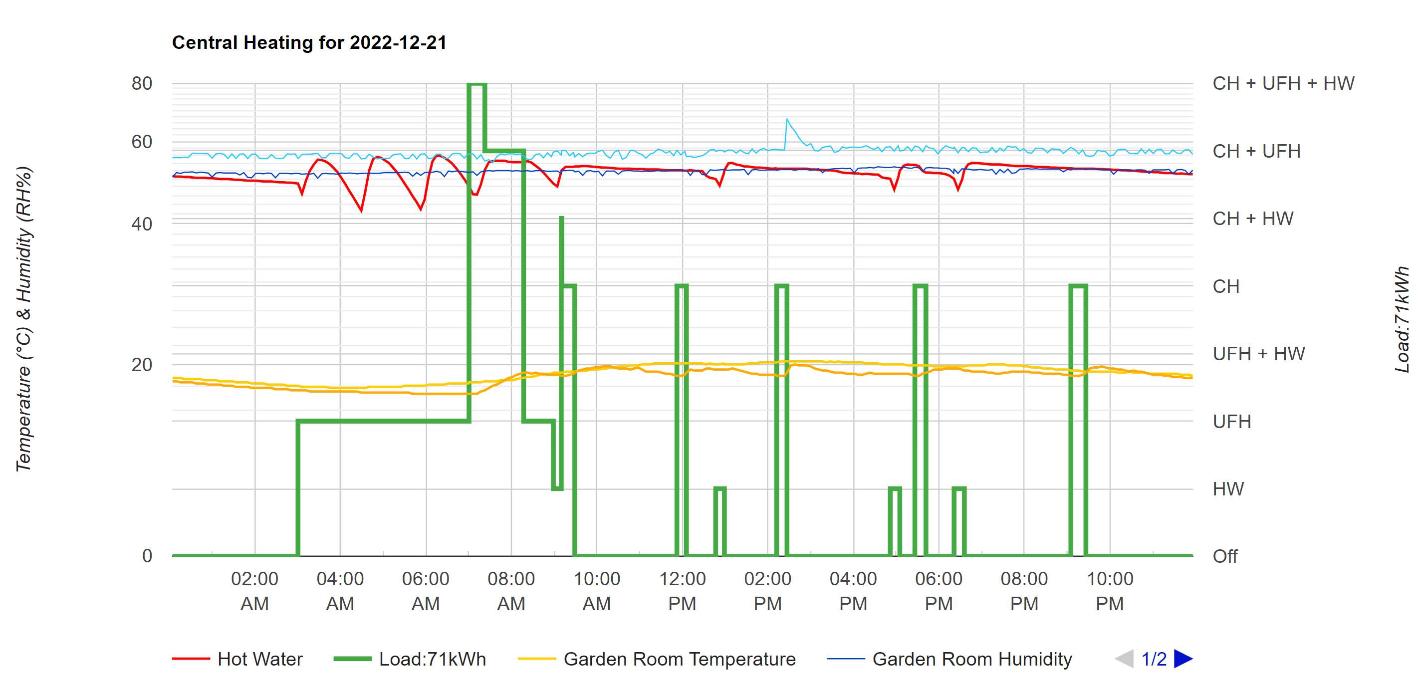
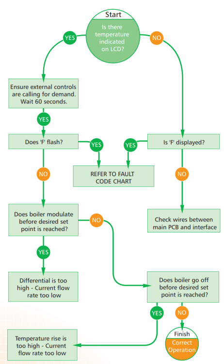
Looking at the Glow-worm technical guide that applies to my condensing boiler, I'm not sure which set point they're referring to in the following flowchart: "Does boiler modulate before desired set point is reached?" "Does boiler go off before desired set point is reached?" Which set point? The demand thermostat or the boiler flow temperature? Because the boiler can have load/weather compensation the boiler flow temperature might be variable so how would you know what the setpoint was? I'm guessing it must mean the external heating controls. Incidentally, I'm poking about in this area to make sure that I have the optimum setting for my circulating pump head.
-
🍻 Merry XMAS everyone 🥂 Had to dig out a 12 year old photo for something festive. Sadly winter snow seems to be a thing of the past here now 😪

-
Hi, the system is S plan with three zone valve bodies (Drayton IIRC) actuated by geared DC motors. I removed the 240V heads and mounted the DC motors on brackets. These are driven by three DRV8833 dual H-bridge motor driver IC's with current limiting so that the motors can safely run to stall and dissipate less than 1W in the closed position. In the open position, the motors are driven to stall for one second and then both sides are grounded to brake the motor - with no dissipation. The main system circulation pump is switched on by the boiler and the UFH zone pump is automatically switched on when the incoming water is above an adjustable threshold. The Raspberry Pi just interfaces to the motor drivers and one 240V relay to switch the boiler demand.

-
What about using a gas barrier paint ?
-
If it ignited behind the gypsum you should have long since evacuated the building. However it's your call on the environmental issues and toxicology.
-
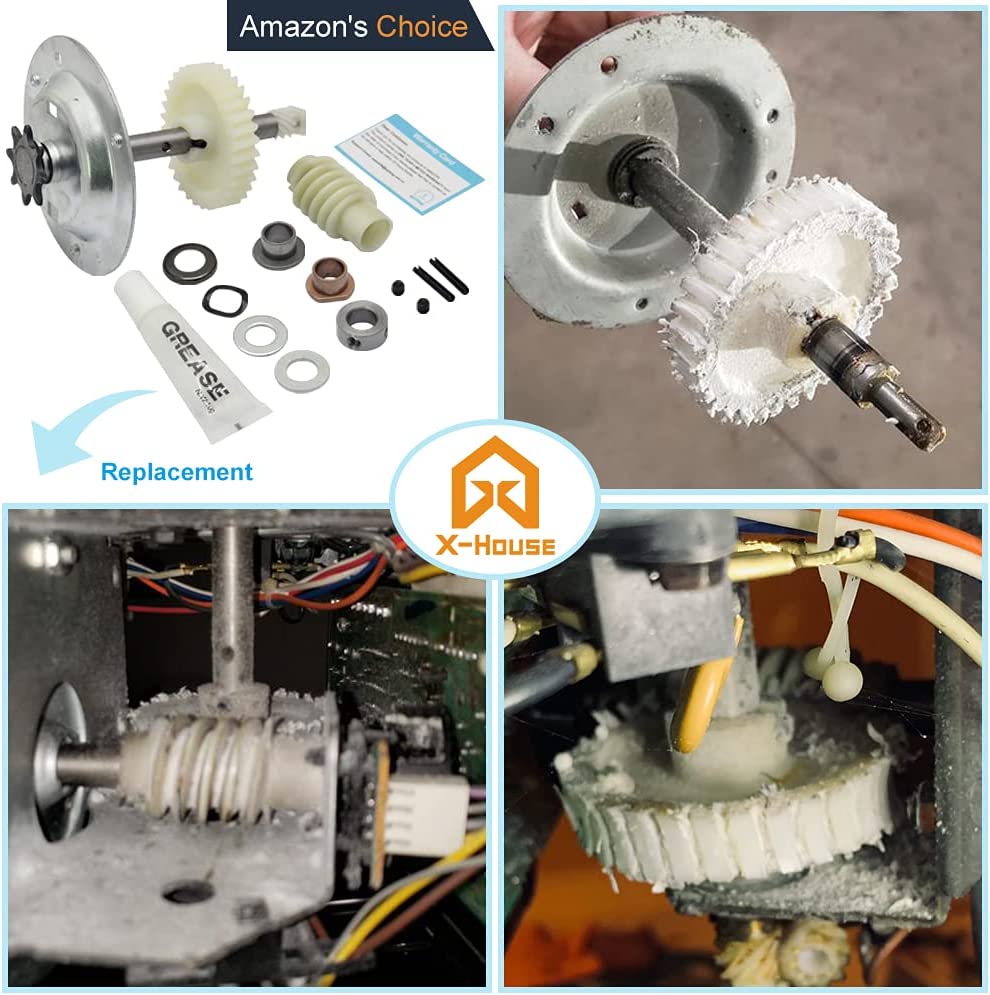
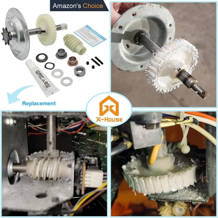
Yes, that's exactly what I did. The only minor difference was a smaller roll pin holding the gear wheel on the new shaft but a little filing made it fit with the larger pins on the old shaft. Now to do the other door I'll just buy the replacement gear - even cheaper! The amazon reviews for these suggest they last about a week so I'll make sure the worm is fully engaged and by sticking with the small sprocket, fingers crossed, it'll hold up. As with all these kinds of jobs, now I've done it once, I reckon I could get it done inside 15 minutes. It's certainly a lot easier than replacing the entire units and considerably cheaper! Funny thing is 25 years ago when I got them we picked them up from a B&Q clearance sale in Poole when they enlarged the shop to Depot. Everything was half price or better so we grabbed two door lifts and a bunch of remotes for less than the price of one motor alone. Doesn't beat the bargain I got in Payless DIY Dorchester when it closed around ten years ago - in the lighting section it was marked 10p for every light bulb. So we filled up the trolley with LED's (about £10 each normally at that time) and whistled all the way to the checkout! Pretty much converted the whole house for half the price of a single LED.
-
I doubt it but what I'm after is the flow and return temperatures as sensed by the boiler. These are accessible from the display on the front of the boiler by doing a tedious amount of button pushing but I want to log them automatically to a DB. I could just hook up a couple of temperature probes to the pipework but I've already tried that and it's never quite in agreement with the boiler display. I want to see the exact same data that the boiler control loop is using. From what I've read online the ebus interface carries all this data and it should be possible for me to get at it, although documntation is very thin on the ground for glow worm's proprietary use of ebus. Yes, that's what I was hoping to get from my simple analysis. I fully take on board what you say about the significance of the return temperature. I was already coming to the conclusion that it might be a good input to my process control to eek out the last few percentage points for efficiency. Serendipity indeed!
-
I just bought a spare boiler controller from ebay to practice reading data over ebus as this should give me a neat way extracting the flow and return temps. I could also do with being able to set flow temperature to do weather compensation. It's not very well documented though so I'm not overly confident.
-
The little tube that came with the kit had a white grease. I could do with greasing the chain - does bicycle grease cover that application as well?
-
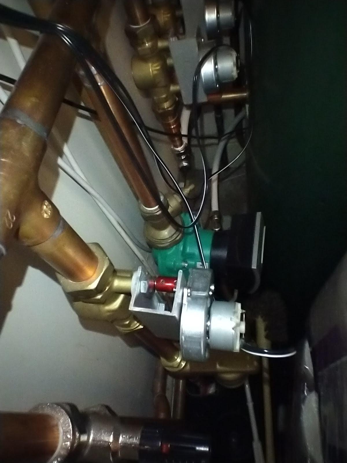
That's a good point. I don't think the motor has any lateral adjustment which could help with this. This photo montage shows how the worm drive sits on the motor shaft. The grease came in a tube like the one shown below.
-
Never encountered this situation before and I'm curious to know how it works - from the sound of it your primary heating circuit isn't gravity fed so you presumably have a pump to supply the house from the bore hole and then a pressurised cylinder acting on the heating circuit?
-
Between what & what? As a snapshot in time, I'm not looking at the actual temperature rise in the room (although I do measure it) I was simply looking at the gas use and relating it to what I'd expect the input to be given the known temperatures of the buffer and UFH loop during the charge/discharge cycling. During this period it's running open-loop (setpoint not reached).
-
Concrete coursing slips are 40mm if that helps?
-
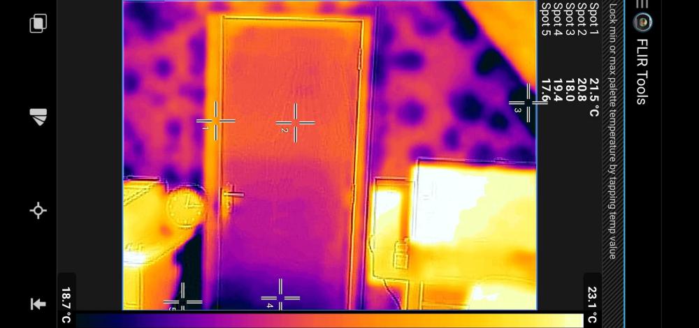
Looking at how much energy is going in now, I've been monitoring the gas consumption while the buffered UFH is the only load, which generally happens in the early hours of the night when the air temperature in the room cools to below 18oC Unfortunately the actual consumption seems a bit excessive when I do some (very) rough calculations: In the above example, yesterday morning saw almost three full buffer cycles from 3AM to 7AM. So ignoring the rest of the day's heating, gas use for each early morning buffer cycle was 6.23kWh, 4.0kWh and 3.61kWh respectively. The initial cycle has a loop full of room temperature water to contend with plus the HW cylinder which is no lower than 40oC at this time of day. So in this case we're heating 150l of water from 48oC to 52oC and 15.5l in the UFH loop from 18oC to 45oC, which given that 1 litre of water needs about 1.16 watts to raise it by 1°C in one hour, requires 1.6 * 150 * (52-48) for the cylinder plus 1.6 * 15.5 * (45-18) for the UFH loop. Of course there's a cold heat exchanger in the boiler and about 25m of 28mm copper pipework to add to this so about 1.6 * 13.5 * (65-18) Adding it all up 0.96+0.67+1.01 = 2.64kWh before we've accounted for the energy transferred into the room. Therefore the energy consumed minus the amount used to bring everything up to temperature should give what's actually heating the room i.e. 6.23 - 2.64 = 3.59kWh The subsequent two cycles are more in line with this (4.0kWh and 3.61kWh) presumably as the losses to overheads are less. Of course the boiler efficiency comes into this so being pessimistic and putting that at 85% might drop each cycle to around 3.0kWh of useful heat input. The pipe spacing and area are actually designed to provide a heat output of 2kW so for the four hour period between 3AM and 7AM and after adjusting for boiler efficiency, I'd expect to see 9.5kWh consumed. What I'm actually being billed for is 13.8kWh meaning 4.3kWh is going AWOL I'm really not sure what to make of this, and whether it means the experiment is successful or not. 🤔

-
It's not a straight cut gear though. It's driven by a worm gear so I doubt if I'd find any off-the-shelf replacement in metal. Even if I did the worm drive would be the next in line for wear. And on it goes...