


TerryE
-
Posts
3806 -
Joined
-
Last visited
-
Days Won
30
Everything posted by TerryE
-
Nick, have a look at the Datasheet for the MLX90614. It runs a proprietary 2-wire protocol that isn't quite I2C. This might confuse the RPi I2C driver, but the easiest is to have a look at the various MLX90614 on RPi YouTube videos, e.g.
-
Anybody used ultra wide monitors
TerryE replied to Adsibob's topic in Networks, AV, Security & Automation
Welcome to the world of Windows. Not an issue with Linux, ChromeOS or iOS -
I have a passive class house which make things a lot simpler. Once a day my CH system calculates the heating required using a couple of 1st order linear functions: one heat required as a function of forecast external temp, and a feedback adjustment on the delta between the average internal temperature over the last 24 hrs and a target set point. This comes up with a total amount of heating energy required. This if the external temp is below a threshold, this is split 80:20 between the slab UFH and an oil-filled rad on the 1st floor landing. Because I use Octopus Agile, it then allocates the heating to the cheapest half-hour slots, so if I need 6 hrs of slab heating, say, then the scheduling will pick the cheapest 12 half-hour slots. These are usually (but not always) sometime between 11PM and 6AM UTC. This is all easy because my heaters have a known heat O/P and my house has such a high thermal mass that it only makes a tiny difference to the heat ripple throughout the day. Doing this would be a lot harder when using an ASHP where the actual heat output is hard to predict or measure and also in a more traditional house where the heating time constant is measured hours rather than days.
-
Fabric and ventilation heat loss calculator
TerryE replied to Jeremy Harris's topic in Heat Insulation
@Adrian Walker, a bit off topic I discuss this in my blog posts, but to summarise for your Q, I have added the manifold out temperatures. This is a Home Assistant plot. My CH system is a standalone RPi running Node-RED. It publishes temperature and other stats ½ hourly to my local MQTT instance and these are tracked by HA, so the jaggies in the plot are partly because of the 30 min subsampling, and partly because the heating is only on when the electricity is cheapest. (Octopus actually paid me to heat the house on a couple of days over the Xmas break.) As you can see the out whilst heating is ~4°C hotter than the return and the temp gradient is pretty even along the loops so the UFH pipework peaks at ~6°C hotter than the slab surface during heating. The heat flows out radially from the UFH loop throughout the slab and within 15 mins of so of the heating stopping the bulk of the heat has spread pretty uniformly throughout the slab at around just over 25°C or 3 °C hotter than room temp. It is noticeable and Jan really like padding around in the kitchen in her bare feet in the morning when the slab is at its warmest. My ripple is was little more that J's: when I measured it with a spot IR temp meter -- about 1°C.- 204 replies
-
- 1
-

-
- heat loss
- ventilation
- (and 4 more)
-
Fabric and ventilation heat loss calculator
TerryE replied to Jeremy Harris's topic in Heat Insulation
@Chris D, I have a warm slab (essentially 17 tonne of slab + another 10 tonne ring-beams wrapped in 200-300 mm EPS) with the UFH loops running in the slab itself. The house is a near-passive design so the slab only needs to run about 3°C warmer at its surface to provide enough space heating to keep the house at ~ 22½ °C which is what we like. Here is a plot of the last 7 days manifold out & return temps: I do my heating using Octopus Agile. The CH algo calculates the total heat required daily and heat the slab at the cheapest ½hr price slots, which are mostly (but not always) in the overnight period -- hence the jaggies. The house is treated as a single zone. Currently the return peaks at 26-27 °C and decays to room temp through the day. The outs are ~4°C hotter during heating. With your house, you will need the slab to radiate more heat, and a conventional heating control will tend to keep the temp in tighter tramlines so the core of the UFH will run hotter, say 30°C, with heat conducting up the surface and then radiating into the room from the floor, but also a lot conducting down through the subsoil because you don't have that 300mm EPS layer. Given that the P/A U-value estimate is relative to external temperatures, then you could be looking at a Δt of maybe 25 °C when you are heating the slab, or 25 × 0.5 × 250 W loss or 3 kW or up to 72 kWh / day of ground heat loss on top of what goes into the house itself. So you need to do your figures carefully. The bottom line is that putting UFH in an uninsulated slab is nearly always a very bad idea. ☹️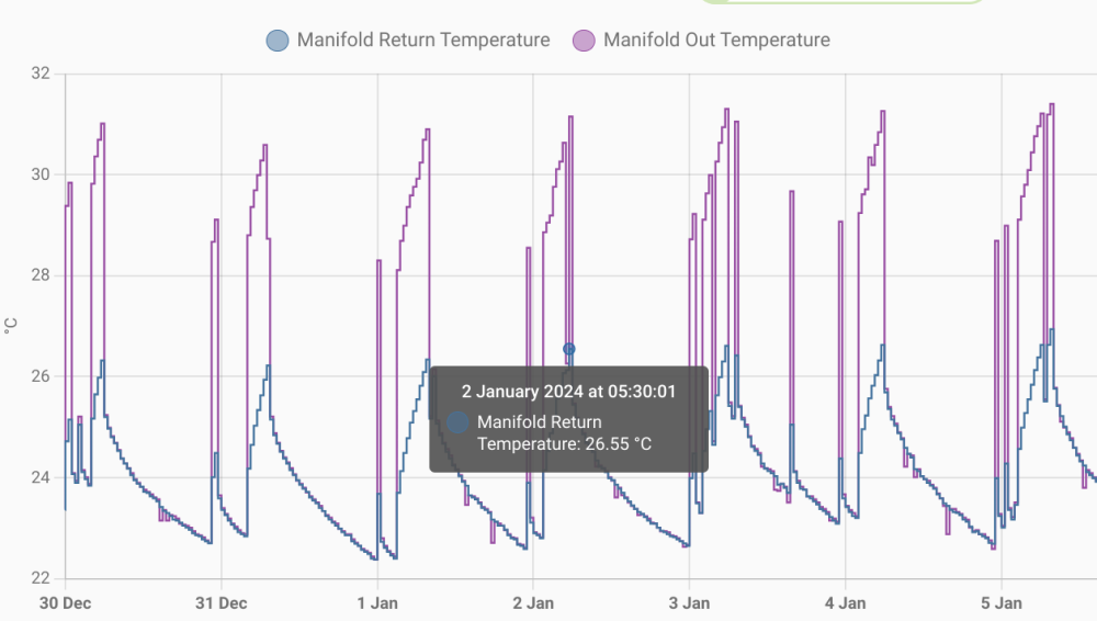
- 204 replies
-
- 3
-
-
- heat loss
- ventilation
- (and 4 more)
-
Fabric and ventilation heat loss calculator
TerryE replied to Jeremy Harris's topic in Heat Insulation
OK, my bad. Having scanned the BRE paper and the CIBSE paper it references, this treats ground leakage as a semi-infinite heat flow to ground and that, given a large enough area, this is negligible (in the limit). The IP3/90 (P/A) and (P/A)² terms are curve fit approximations which reflect edge and corner leakages and these heat flows dominate the losses. Note this is all rough order empirical estimation, and as @Redbeard's reference state "On a cautionary note it must be stressed that the following table is based on approximate calculations as detailed above and is for guidance only. It is intended to help give some ‘feel’ for insulation requirements". So @ADLIan's advice is better than mine. 🤒 -
Fabric and ventilation heat loss calculator
TerryE replied to Jeremy Harris's topic in Heat Insulation
Eh? This is about 10 × smaller than the radiant equivalent. It doesn't pass the sniff test. What is the source for this statement? -
Fabric and ventilation heat loss calculator
TerryE replied to Jeremy Harris's topic in Heat Insulation
Picking up @JohnMo's point, your floor is acting as a near to perfect heat sink. However the ground temp under the house will be in the 8-10°C range. Hence a bare or tiled floor will soak up about 6-7 W/m2K so if the Δt air:floor is 10°C that's 6×10×250 W or 15 kW and that's 24×7. That's nearly all radiant, so the "heat rises" adage, as John says, just doesn't apply. However, adding a decent fitted carpet and underlay throughout will make a big difference as this in practice is the main insulation layer. How much is moot. I suspect maybe 2 or 3 × factor reduction. -
Not just any relay, you need a decent SSR or contactor rated at 240V AC and 16A load for a 3kW resistive load, and wiring these up needs some electrical knowledge, as it is quite easy to do this in a way that breaches code. I played it by the book and got my sparky to do the 240V stuff and sign it off. I used SSRs so I could drive them with 5V DC. You can get contactors that are driven by 12 and 24V DC. You don't need low voltage stuff signed off.
-
We have a democracy in our house. It's just that Jan has 1.1 votes. 😉 What she hates about the SunAmps is their unreliability (due to control board failures): we are both in our 70s now, so reliability is becoming more important than ever. TBH, if we were in the situation of @Cooeyswell and only had one unit then we would have given up on the SAs long ago. We have been looking at our utility room and we can fit an OSO tank opposite the toilet; a job for next summer, maybe. This needs more mulling time to refine options. @MikeSharp01, I really like the idea of the SunAmps and the physics behind them, but they seem to be really let down by the engineering implementation. 😪
-
@SteamyTea, I just checked the SX 210 - VIP model which has a 193L water capacity. The heat loss is 1⅓ kWh / day which is about 30-40% higher than 2× SunAmp PV, but I could live with that. The killer (for me) is it's dimensions (1.3m high × 0.58m). I can't put it on the deck because of the other stuff in the services cupboard that I can't move (the UFH pipework, manifolds, rising main, etc. so it would have to go on a shelf -- pretty much in the same place as the SunAmp. I have 600mm depth to work with so it would be very tight, and I'd have to move my Control Panel. And then the OSO is a UVC so all plumbing would need to be done and signed off by a certified plumber, so he or she would need to sign off the installation. So this isn't an easy refit for me. ☹️
-
In our case, all of our services are in a small cupboard off the utility room toilet. We would have difficulty fitting in a cylinder and the hot losses would turn the toilet into a sauna. And @MikeSharp01, I will talk to SunAmp first.
-
That SunAmp PV of mine has failed again, so I am down to 1 × SunAmp PV again. It looks like the safety thermostatic cut-out has tripped again. No good reason. I had a DS18B20 on the heater wall and it never got near a cut-out temp threshold. I like the unit but the control electrics board is crap. I am seriously considering replacing it by an off-the-shelf ESP32-based control board, and reimplementing to control myself.
-
Logging OVO Actuals Data and Octopus Agile Half-hourly Prices
TerryE replied to TerryE's topic in Boffin's Corner
There is a Feb 2019 Octopus blog post, Agile pricing explained, that give a lot more detail on the makeup of the pricing formula. They've since tweaked on of the coefficients for later contracts and hence the formula for your contract is available on your account portal. -
Logging OVO Actuals Data and Octopus Agile Half-hourly Prices
TerryE replied to TerryE's topic in Boffin's Corner
@Alan Ambrose, another way to look at it is that OVO seems to use a ~3× markup instead of a 2×, but instead Octopus puts a premium on the 4-7PM window. Our use is pretty flat outside the 0-7AM windows so I would take the 14p peak premium anyday for cheaper prices (overall) for the rest of the day. -
Sorry to hear that. Maybe ask them to scan this post. 🤣
-
The drawing above shows 50mm insulation. However 150mm EPS has a U-value of around 0.2 W/m2K. Can you get vacuum panels formed on the curve, or AeroGel blanketing. You'd need something like this to achieve this. My other cry here after my SunAmp on a shelf experience is: Maintenance Access!!
-
If I remember what @Nickfromwales said, they've pared down the UniQ design. Instead of using a heating loop with pump and (external to cell) inline water heater to heat up the salt cells, the UniQ cells have an electric heater in-cell. The upside of this is that the engineering is significantly simplified, but the downside is that if the heater fails then it might not be a simple field replaceable item. Maybe a more knowledgeable UniQ owner can comment. TBH, if my current PVs failed or became End-of-Life unrepairable then I would still have SunAmp at the top-of-list as a replacement supplier.
-
@Russdl, if you take the lid off, it is an inline Y intake filter located above the heater (on the opposite side to the entry ports). On mine, the maintenance access port face downwards so it isn't easy to maintain or to access and you need to remove the side panel to do so, so you need the unit cold first, ...
-
Yes, there is one inside the PV models on the recirculation path, but not in the UniQ ones AFAIK.
-
That would both strain the pump and tend to cause the heater to trip. I already have a Y-strainer on my rising main to prevent this sort of crap getting into the house potable supply in the first place. (I have checked this once about a year after we moved in but it's probably due for a recheck). I thought that these have been standard in new builds for years. Didn't your plumber fit one? I will check mine as part of the "5 year service" that I mentioned about, but you need to take the side panel off to get at it. (Loop back to previous caveats on doing this.)
-
And here is the Heating Curve for last night's heating cycle. Note that the funny ripple is because I have 2 SunAmps, but I decided only to have one being reheated at any time (as the Willis is also typically running as well), so they alternate getting 15 mins each for 3 hours heating. Note that we'd had a big bath last night so the SunAmps were pretty low on stored heat. Also the SunAmp reached the cutoff temperature at about 6 mins into the last 15 min cycle.
.png.731c1b28e781f2d88ed02715fe268d43.png)
-
@Cooeyswell, BTW, this is easy to diagnose with the lid off if you have a multimeter with decent probes. The cut-out has 240V live in & out push connector terminals on it. The resistance to ground should be around 18Ω (Ohm's law for a ~3kW heater at 240V) when measured at both sides. If one side is open-circuit, then the thermal cut-out needs reset. However, if this happens then you should really get to the root cause. PS. Turn off power to the unit before you start poking around if you don't want any flashes or jolting surprises.
-
@Cooeyswell, do you use something like a Harvey water softener on your potable water supply? If you don't on the HW, then pipe furring can become a real issue over time and cause TMVs etc. to fail as the fur builds up in such devices and pipework. This is why the SunAmp people say that you should using a water softener for all potable water if you have anything but a very soft supply. This is especially the case as heat cycling causes calcium salts to precipitate out on the surfaces inside the SA. Unlike the classic CH pipework which runs that water in a closed cycle and you add scaling inhibitors to it, the SAs use open-cycle potable water so scaling will become a problem. (Think of what happens inside a kettle, and hint: if you need to descale your kettle even once a year then your water is too hard and the Sunamp units will fail over time.) If your circulating pump is getting noisy, then you do have a furring problem. If you are in this situation, then the unit might need a complete strip down and descale. However, note my above high-jinks: the SA unit needs to be cold before you attempt any panel removal for disassembly otherwise the cells will sag and bulge, and you won't be able to reassemble. I suspect that this a 'once every X years' sort of service, where X depends on residual hardness. (In my case I am at 6 years, and X is probably 5. 🤣) This is all a pretty straightforward job, if you have any plumbing experience as the pipework has demountable joints at all the necessary places. Just make sure you know how to demount standard compression, Pegler Tectile and John Guest Push-fit fittings before you begin. (Watch a Youtube tutorial.) Also take a load of photos during each stage of disassembly, so you can reverse it to reassemble. One of my big bugbears with the SunAmp factory assembly is that they didn't use PTFE tape on the standard compression couplings so many of mine have wept over time until being sealed by the weap furring; these will all need clean-up before reassembly. I guess that this is a job that I am going to have to schedule for next spring, if I want my SunAmps to last another 6 years. In my case I have 2 units, so I can do one at a time without loss of hot water. My concern here is that the thermometer on the heat outflow is an analog one that is clipped to the output pipe: any scaling in this pipe section will cause this thermo to start to read low so the SA control algorithm will tend to run hotter over time and eventually the independent safety cut-out (which trips at ~80°C) will start to trip. I have now lagged around these thermometers, so hopefully they don't read low now. In my case, I already have a load of DS18B20 digital thermometers wired into my CH system (which runs using Node-RED on an RPi). So it is relatively straightforward to tape another DS18B20 to the pipe coming out of the heater (next to the analog thermometer that the CS control uses and to gate the SunAmp demand on that, so that the SunAmp never overheats. @Nickfromwales, you are probably the most experienced member with installing and using SA units. Have you any comments or advice?
-
Logging OVO Actuals Data and Octopus Agile Half-hourly Prices
TerryE replied to TerryE's topic in Boffin's Corner
One of the things that I really like about Octopus is their pricing transparency. They publish their pricing formula on their customer portal: they add a 100% markup on the wholesale spot price for their distribution costs / overheads + a 14p premium from 4-7pm UTC to incentivise Agile customers to avoid the peak demand window. There is also government mandated 100p / kWh price cap. 100% might seem a bit steep but overall this is still working out at ~30% less than the OVO E7 tariff.
