Spinny
-
Posts
923 -
Joined
-
Last visited
-
Days Won
1
Everything posted by Spinny
-
Sorry but this is tautological nonsense worthy of Orwell's 1984. What you refer to as a 'conspiracy theory' is factually either true or false. If it is shown to be true, it is no longer what you refer to as a conspiracy theory. Whether it is true or false is not determined by what is in the minds of those who trust the official line - it is determined by actual factual reality. Do I need to remind you officials said 'If you take the vaccine you won't get covid' FALSE, 'The vaccine is 95% effective' FALSE, 'Face masks don't work' TRUE, 'Face masks do work' FALSE, 'Two face masks work' FALSE, 'The covid IFR is 3%' FALSE, 'The vaccine is safe' FALSE, 'The vaccine is withdrawn because it is unsafe' TRUE,'infection acquired immunity doesn't provide protection' FALSE, 'stand 2 metres apart to stay safe' FALSE, .......
-
Simpson strong-tie do a lot of ties and brackets. I found the MTS30 useful and capable of being covered by plaster. Services of a structural engineer useful for loadings though. https://www.strongtie.co.uk/en-UK/products/medium-twist-strap-mts
-
That is not an argument, it is meaningless. It was the ''accepted'' truth that the sun went around the earth. Obvious and undeniable, everyone sees it happen with their own eyes. Supported by state and church, overwhelmingly believed. That doesn't make truth. You don't find the truth by taking a vote. I haven't claimed any conspiracy, just that there are opportunists, vested interests, and dedicated followers of fashion out there. Tulip bulb anyone ?
-
I should probably not comment given the heated certainty that too many seem to blindly possess on things like anthropogenic climate change and covid. There is nothing wrong with doubt, doubt is good, science IS doubt. Often the obvious is false, and reality stranger than any fiction. Beware adopting simple certainties in a complex world. People used to think it obvious that the sun goes around the earth, that no bacteria could survive in stomach acid, did rain dances to the gods, and burned witches. There is zero evolutionary difference between those people and ourselves. But I will say that too many confuse their own personal perspective and experience of things like covid with the wider population significance. There are of order 5000 NHS intensive care beds serving a population of order 60,000,000 - so that is of order 1 intensive care bed for every 12,000 people. The number of people in intensive care is completely insignificant on a population basis and even if it doubled or trebled or quadrupled in a pandemic it would still be insignificant on a population basis. Now if you work in an intensive care unit and the demand doubled you would think the sky is falling in - can't cope - no beds - people dying right , left, and centre - stressed out - panicked. And plenty of journo's would be happy to relay your message of the falling sky to the masses. But it would still absolutely be insignificant on a population basis. Likewise if you work in care homes there are 450,000 beds in England - still less than 1 in 100 people - and on average they normally die within 2 years anyway. If you feed them midazolam as soon as they get unwell, they die faster. So it is entirely consistent for some people to think covid was the sky falling in, while in a very true sense it was insignificant on a population basis. I attended a covid funeral by videolink and was very upset and sad for the loss, and the inhuman way the widow was made to sit alone isolated from comforters. At the same time I don't have a problem with simultaneously recognising that it actually was insignificant and minor at a population level. Whether we like it or not, or admit it or not, human lives have a price - yes even our own glorious and virtuous life. The NHS routinely rations care and drugs based upon QALY (Quality Adjusted Life Years). During covid the UK and much of the rest of the world was whipped into a mass hysteria of delusion and panic where it suddenly became ok to spend unlimited sums 100 times higher than the NHS would ever normally do - to save a life. It was and remains a time of utter, utter, madness. Actual science was ignored, psychological operations took place to broadcast fear into every household. The UK spent £500 Billion to negligible population effect, and engaged in hugely counter productive actions, denying people jobs, education, health treatment, social contact, exercise etc etc. Now we are still paying the price for the folly - remember that when your taxes go up again in November. Remember the higher school absence, the ongoing epidemic of mental health social security claims, the kids with lives scarred forever, those dead from untreated cancers, the bankrupt businesses, the huge inflation, the high interest rates. It was folly.
-
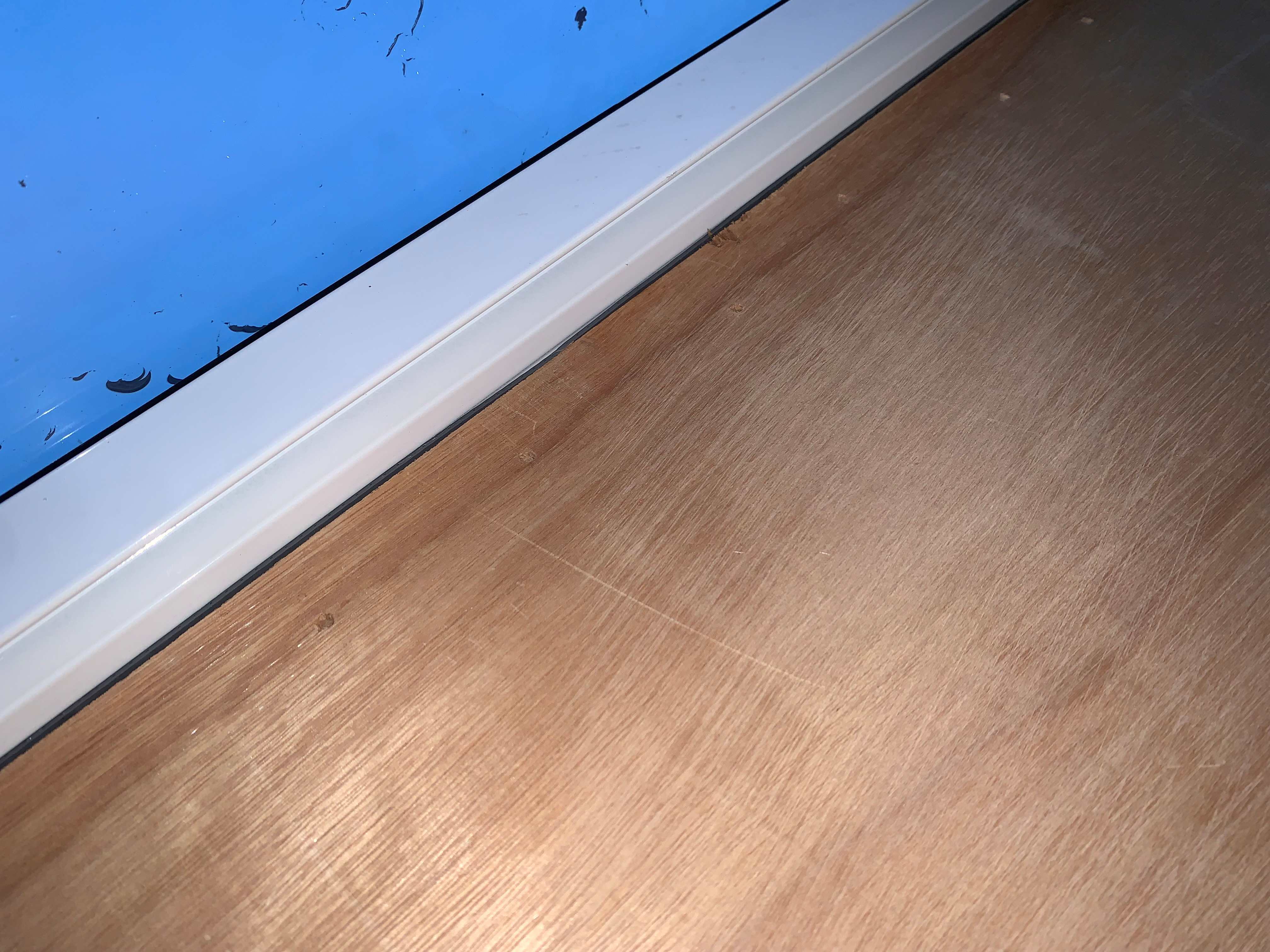
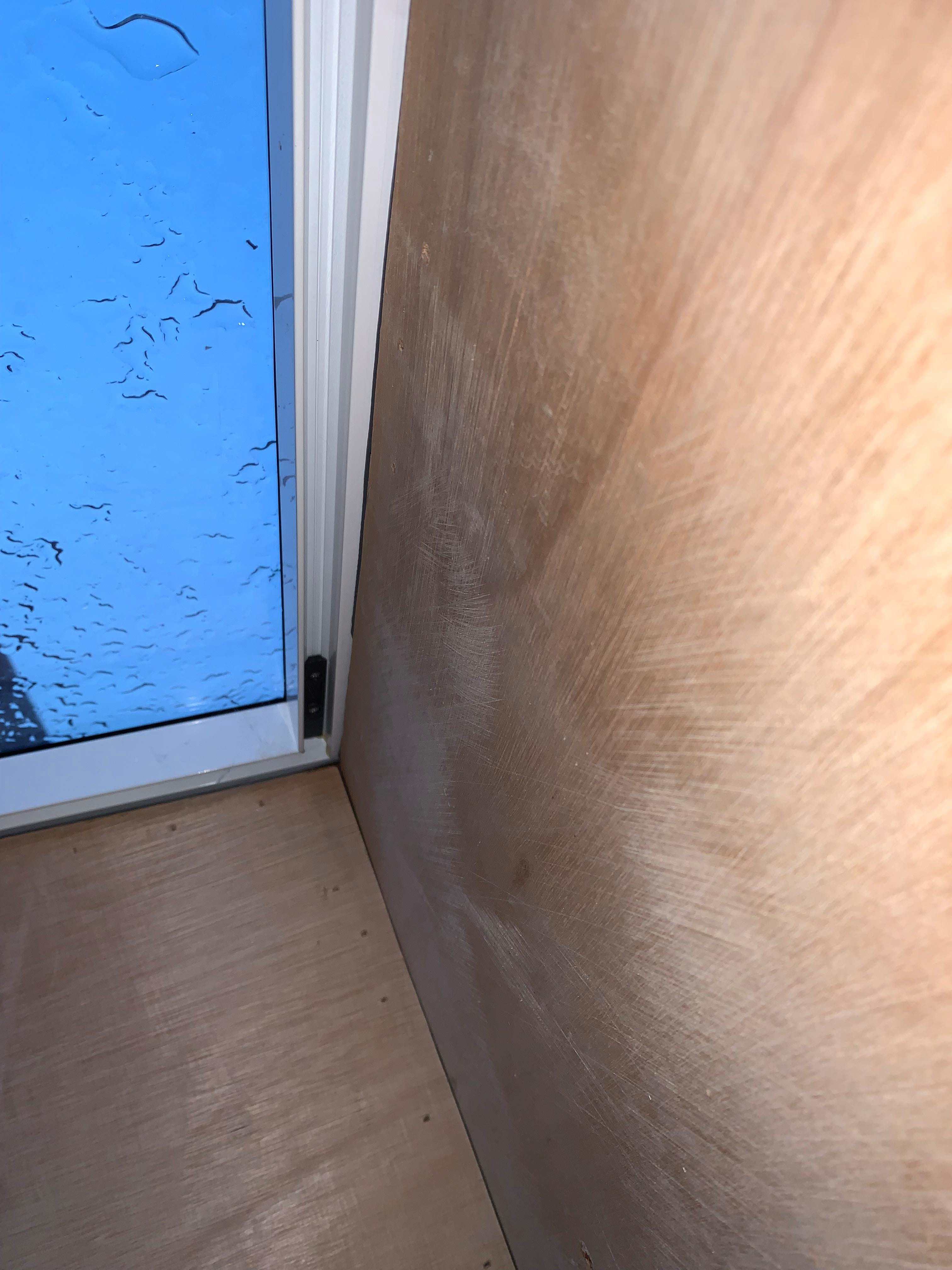
Tricky. They are supposed to be building on the edge of the foundation. Have machine dug a deep trench certainly 1m deep and 600 wide along the line and also hand dug out clay etc. from above. Inevitably the side is not completely straight and true. Excavation on my side is undesirable, there is only a 900mm gap and my own drainage runs down it. They have been hacking at the sides a bit. 20% of their brick inspection chamber hanging above the trench and clay pipe collar chipped off (plan to repair with cement ?) Gas have told them they can't come for 8 weeks to relocate the gas pipe & meter but apparently they can dig around it. Have self certified for lateral drain which is just over 0.5m from front of extension (but they are building a platform and steps forward and over) - considered £300 for a build over agreement as unwanted cost. Not entirely reassuring.
-
Neighbour is building a side extension to boundary, so should the foundation trench be shuttered on the boundary side before the concrete pour ?
-
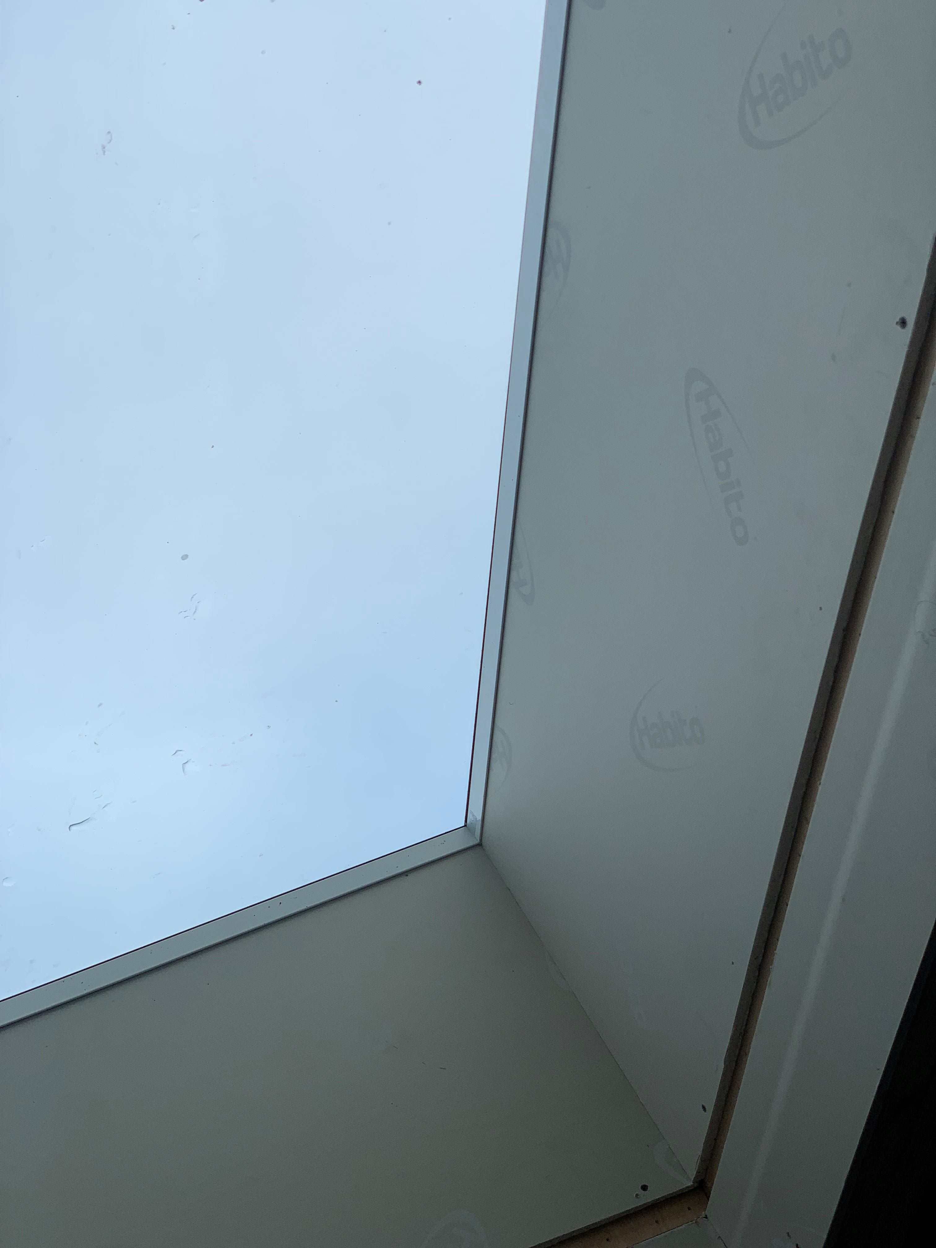
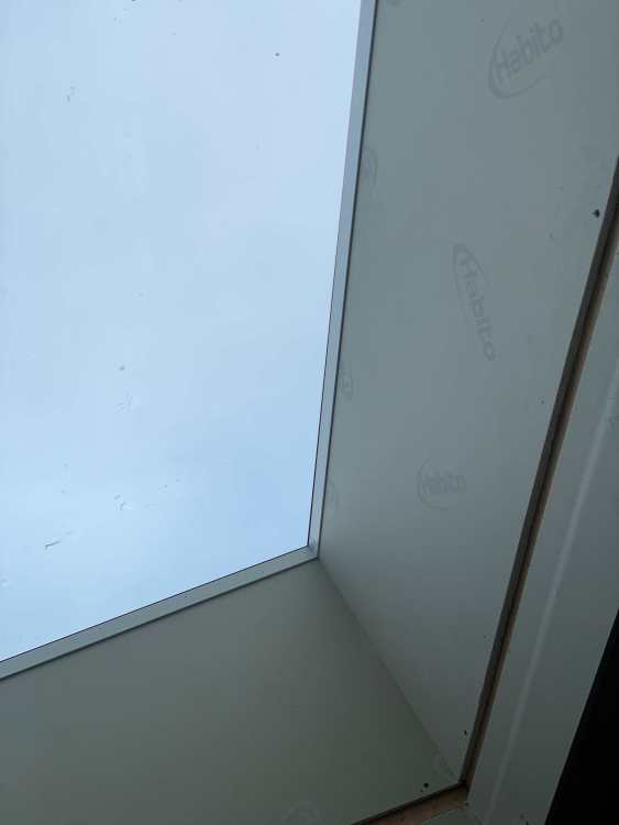
More photos as requested. This shows the roof light upstand without plasterboard fitted and the edge of the rooflight. The rooflight has a channel in it for plasterboard to slot into and the top of the rooflight, channel, and trim is made of powder coated metal. Once the plasterboard is slotted into the edge there is a proud lip of 2-3mm so it can be plaster skimmed up to flush with the edge of the trim. I was told it can be double plaster skimmed to cover the trim to give a plaster to the glass look and that they routinely had customers that did this. Tape ? Blue Grit ? Have I been lied to ?


-
Personally although I have an iphone I hate the idea of allowing Apple, or Amazon, or Alphabet, or Microsoft to have control of every aspect of my tech usage. I consider these companies as leeches striving to turn all our lives into a 'life by corporate subscription' model. It is the problem that keeps besetting technology - companies refusing to just compete in an open market place and instead striving to hook people into a single corporate tech ecosystem by proprietising open standards and building in incompatibilities to exclude competition. It has happened in AV with DLNA, and it has happened in Home Automation. Corporate greed gone mad - who the hell WANTS a door bell subscription. I think forget adopting one monopoly and focus on how you want to do the physical wiring, switches, back boxes, conduits to support automation capability and above all flexibility. Many HA people use devices from many suppliers and multiple technologies at the same time - zigbee, zwave, wifi, bluetooth, etc. etc.
-
Thanks, sorted. I also found some masonry holes/plugs were not lined up with the holes in the strap with screw heads therefore sitting at an angle. With the screws out there was just enough movement to allow me to drill the odd new hole directly in line and straighten up the screw heads too. PS Is there a spec for what screws should be used ? (Builder has used 60mm yellow passivated type)
-
Mounting frame of recessed light gone in ceiling - can't get down
Spinny replied to Question's topic in Decorating
OK you solved it. I was just going to suggest in extremis perhaps you could buy another light the same (or get your spare one out of the loft), disconnect the trapped one and push it aside in the ceiling cavity, then connect and fit the replacement light. -
@Nickfromwales Any more thoughts to offer on this one ?
-
I have some walls to be wet plastered which have roof restraint straps running vertically down the blockwork for 80mm from the ceiling. One in particular is bent at the bottom and with its screw head sticks out from the wall by 10+mm. Any tips on dealing with this ? Presumably I can't just cut the end off ? Any way to bend it straight in situ ? Any flush screw head fixings for these things ?
-
I agree Kelvin and have had extra lighting circuits and deep or double back boxes put in at the switches for relays. That is why I am looking for ceiling downlights that... (a) Are dimmable or take dimmable GU10 bulbs (b) offer a high lumen output - i.e. more than the 350-400lm a lot of GU10 and smart bulbs or smart downlights seem to offer - my ceilings are 2.62m high and with age there are times when bright lighting is welcome for tasks - and with dimming you can then chose any level downwards as desired (c) Offer some form of CCT as per the usual higher kelvin in the day and lower kelvin in the evening pattern, and for temp control to match other lights in the same area. Smart CCT control seems ideal, physical CCT switches behind the ceiling, or swapping bulb temperatures much less so (d) Baffling seems desirable to reduce glare, but then in some areas a wider angle of light to give general lighting. (e) Plaster in lights look contemporary and we have put some baffled GU10 ones in one room already, but high lumen GU10 bulbs with CCT don't seem to be on the market. (f) Adjustable (tiltable or scoop downlights) needed for some areas for flexibility and highlighting pictures Many people seem to just plonk in an array of off-the-shelf cheap fixed downlights, but when you start looking at lumens, CRI, beam angles, plaster in, adjustable - and then want smart too, it seems to get more difficult.
-
Anyone got any experience or suggestions regarding smart light brands and smart downlights ? Need to finalise and buy for our open plan room. Ideally zigbee or zwave but willing to look at wifi. Dimming for sure, CCT, good lumen output.
-
Yes. Our builder decided to tack mortar the course of blocks running under our bifold opening - on the basis it would make it easy to remove them to machine cut to threshold height later. Turned out months later we discovered those blocks had bowed out into an arc under the weight of the concrete pour - leading to much delay and remediation work. (TBH It was a larger open slab - about 40 sqm - and a 3.5m opening). How deep is that concrete going to be ?
-
This. And too high is too high - you are ****ed. But too low is fixable with levelling compound.
-
You don't say how thick the concrete is going to be ? (We had our pipes tied to the mesh rather than the insulation and had a polythene vapour barrier) I'd have thought you need a detailed military plan for the day with some possible fall back options and everyone pre-briefed. Talk to the concrete company to try to understand exactly what to expect from them. We ended up with an old pump lorry because the newer one was in for servicing, no flow control at the outlet end of the pipe, people had to shout and wave hands across a 30-40m distance to get the pump turned on and off. A significant delay between off and the flow ebbing away. At the beginning you can get a very watery slurry coming out of the pipe at first, so might possibly want to consider dumping this somewhere (out of a doorway or window or into wheelbarrows or something ?). At the end the concrete remaining in the pipe has to come out, so you might want to have a plan for where this can be dumped - we ended up with a considerable concrete mass on our driveway until we eventually got the builder to remove it. Know where the mixer and pump lorry are going to park and ensure it is clear of vehicles. Have plastic sheeting and tarps available so you can protect the road/driveway as necessary from leaks that may occur under the lorries. Know what the options are with the concrete company if things were to go wrong - lorry arriving late or early - having to abort part way through (will they then empty onto your property regardless etc) - job taking longer than expected. Check those volume calculations and know what you are going to do in case of shortfall or surplus. Have boards avalable - we had a 6m board spanning our footings from one side to the other - not sure how that works for an existing building. Do you just work back from the far room, or is it feasible to do one corner room, then move to another corner room while someone is finishing/checking the first, then move back etc - I have no idea as I've never done it. Do you assign a person to each room ? Who does what exactly ? Will they be dressed appropriately - our builders young lad turned up in shorts and shoes and had to have concrete washed off his legs FAST to avoid concrete burns - brickie turned up in long protective trousers, gloves and wellington boots with shovels. Pipes full of concrete are heavy and they can jump about a bit when the pump is running so make sure the pipe itself doesn't damage anything. I had to put some bits of insulation around the corner of our house to protect it.) I am sure you must have any conduits, drains, manifolds, services in place - u/floor heating pipes pressurised - perhaps your cabling and plumbing pipes are going in the ceiling and walls ? Keep the egde insulation higher. Levels can be tricky - have you used a water level to double check them - maybe know what your tolerance might be at doorways. Splitting the pour may cost money - but how much money is it going to cost if things go wrong - likely an awful lot more.
-
Is it feasible to successfully plaster over my roof light trim (see pic) ? When I bought it the manufacturer said yes, just double skim the upstand taking the second skim coat over the white trim. Now my plasterer is suggesting no, because it will crack, the only way would be to double line with a second layer of board over the trim - which would then then reduce the opening by 25-30mm each way. The trim is powder coated metal - not plastic.
-
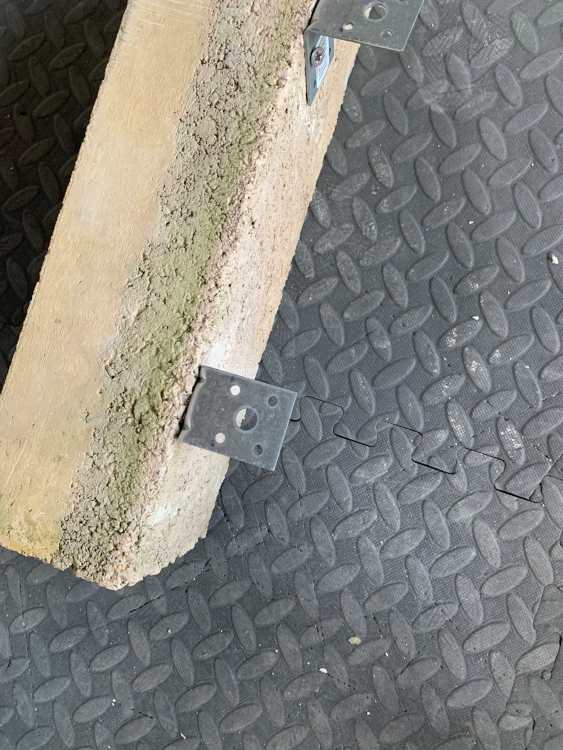
Yes I was thinking of that. However having opened things up I have the following concerns: A. The existing EPS on one side already reaches down to the bottom of the cavity but still has some movement in it and so doesn't seem rigid enough to offer any support to any concrete above. B. So the only thing that would seem to be supporting any concrete would be it's sideways bond to the inner celcon blocks and two things concern me - 1. Can I get a strong bond to the celcon blocks or might it break away over time and - 2. vertical weight onto the concrete would create a turning force onto the selcon block and might pull on its mortar joint loosening it. Our builder had issues fixing celcon blocks elsewhere in the build and it makes me nervous of putting them under anything other than vertical forces. C. The outer leaf concrete block was damp where is goes below ground (to be expected I suppose with the rain we have had) and there was some moisture on the bottom of the EPS in the cavity there, so uncertain whether a small moisture gap under the EPS was better than pushing it hard down onto the bottom of the cavity. Photo shows a test fixing of an angle bracket into a surplus faced concrete block - which make up the outer leaf. Thought being could I put one every 150mm or so across the reveal to support a board over the cavity. (putting some DPM behind each one and XPS around). Not very easy to fix with a celcon block just 100mm away of course Have also thought about say angle brackets with one leg long enough (say 150mm) to span the cavity and so be also fixed vertically into the top of the celcon block. Yes a thermal bridge between outer and inner leaf, but with insulation board on top and the celcon blocks maybe not too much of a compromise to matter. And that is where I am, caught in the headlights a bit like this guy...https://youtu.be/GezQvcbPaYY?feature=shared
-
Still dunno what to do here... Contemplating whether to try to screw angle brackets to the outer concrete block leaf to support some closure ? Would Toupret exterior filler stick to the inner celcon block ? (though I am nervous of exerting sidways forces onto blocks the builder struggled to mortar well.
-
BS Our paid scientist says anything at all we pay him/her to say. And there are multiple dodgy people paying for this cargo cult science with ulterior motives.
-
Yes and no. I have zilch experience just one build and 3 years of issues. I have no direct experience of LABC. My BC provider has been OK, but I would say inspections have sometimes seemed cursory, not lifting the carpet to see what might lie underneath. I recall having to ask them to come over and look closely with me at how the radon, vapour barrier and DPM had been done by lifting up sheeting to reveal it. No doubt experienced people cast an eye over and would say they can tell at a glance whether it is a well managed site with a competent builder - no need to dig. In contrast workmen told me stories of jobsworth LABC taking 5 days to turn up then insisting the foundation trench was 100mm short on depth so yes they would have to spend days diggin and cutting into bedrock. There are also chunks of the regs left open to judgement and interpretation. It feels a bit galling when you have ticked all the boxes working with an architect and structural engineer on test pits, soakaway sizing, radon barriers, fire rated cladding, wired smokes, drain design, lintel calculations, steel specs, vent positions etc. Then you see someone doing none of that and sowing seeds for future owners of that building for the next 100 years - sign it off when done - no soakaway, no radon control, timber cladding, a battery smoke, built over drain, no calcs, vents in non permitted places. Call me a sceptic when it comes to human nature.
-
Mr Punter I'd rather not have a dodgy extension built on my boundary and uphill from my property. I think that is natural. I am told the builder has known the BC for over 10 years. It appears to be being done on a budget, build over drain, no soakaway, no construction plans, no building notice, ignorant of gas and sewer regs. So yes I will keep my eyes open. If your neighbour drove down your road at 50mph and nearly knocked someone down, you might want to do something more than 'none of my business', or if your neighbour started building something 20ft high in his garden, you might want to do more than 'none of my business'.
-
They intend to leave the existing tarmac down underneath the suspended floor void in the extension. Any building regulations about that ? void will be about 800mm deep.
-
They have access onto my property under the Award. They cannot build on or over my property. Indicating a 50mm set back only (flat roof). You don't need a projecting foundation, you can build on the edge. Just had to inform the builder he can't build over a gas pipe. They plan to build over the drain chamber (poor practice).