Spinny
-
Posts
923 -
Joined
-
Last visited
-
Days Won
1
Everything posted by Spinny
-
Any advice on choosing and using coving. Only ever chose some simple coving 20 years ago. Seem to be different many types, materials, lengths available now which is confusing. Some samples seem to cost as much as a full length. Does it need to be done by an experienced decorator to get a good result ? Any good places where you can actually see lots of samples or see installed examples ? Is there a recommended approach to dealing with coving around bulkheads ?
-
OK, I already have the tap. Yes it comes with 400mm flexi tails. However I see online flexi tails are available in 100mm length, and good old copper tails are also available which could presumably be cut shorter to any length and sleeved in black. Just need a black 90 degree bend then ? (Seems like chrome can be spray painted black so might have to do that ?) Except when sat on the khazi.
-
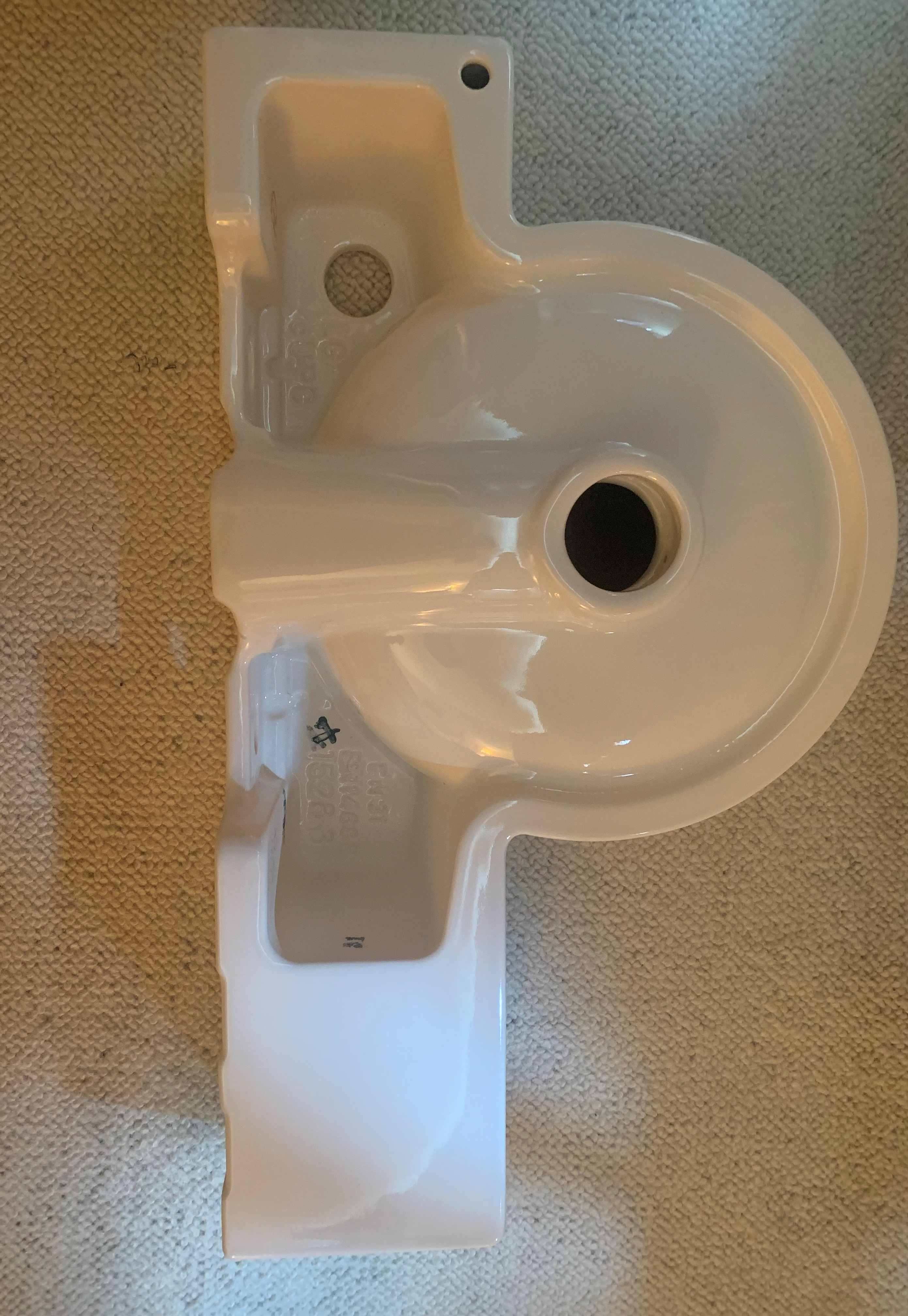
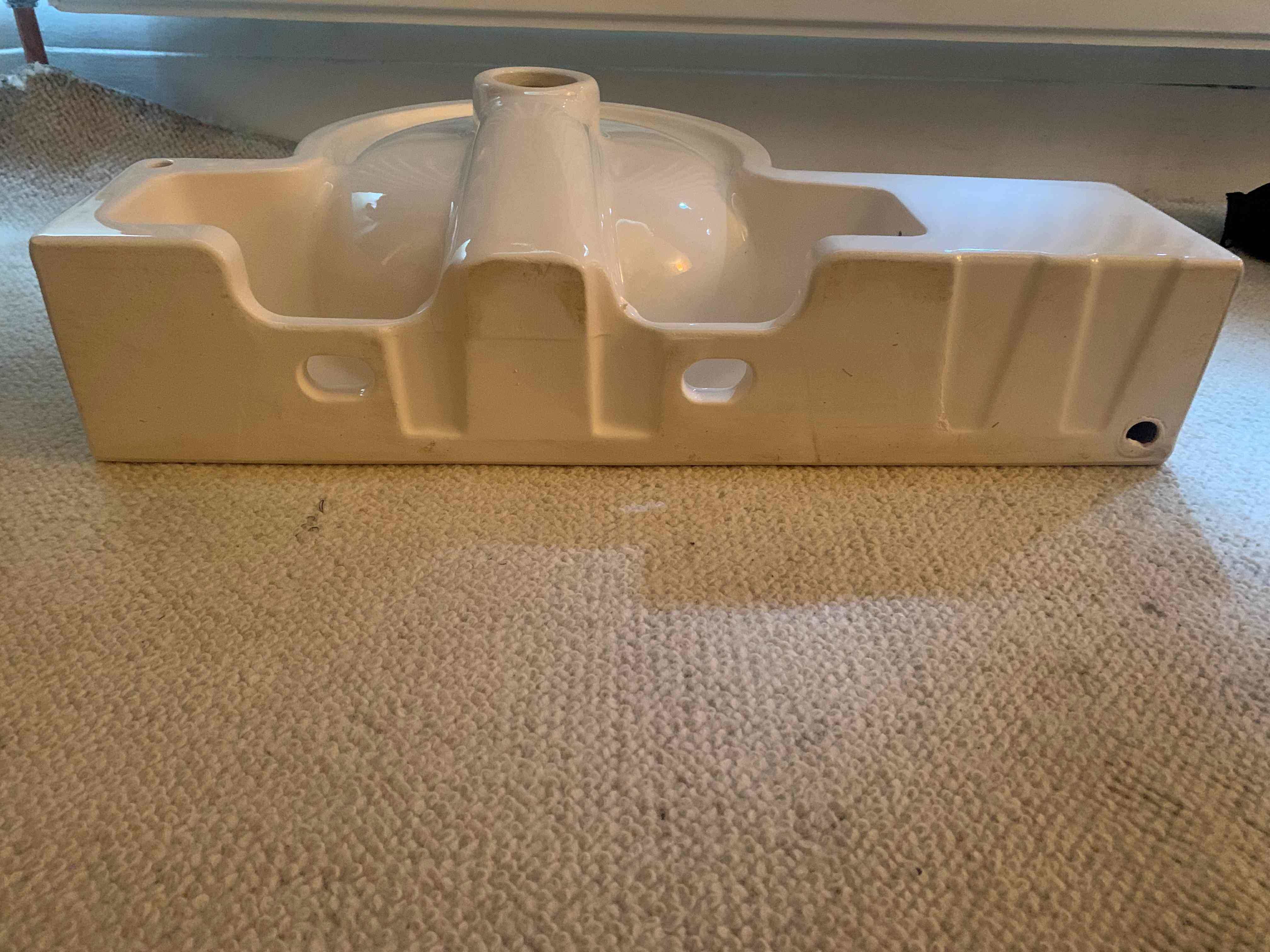
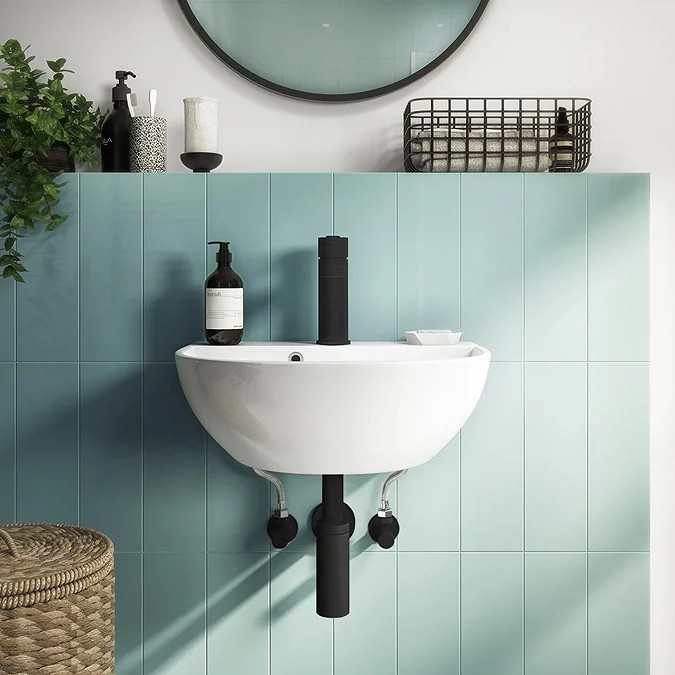
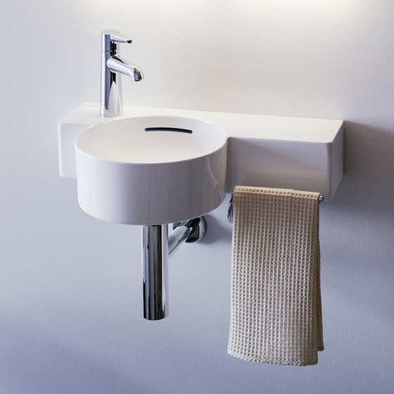
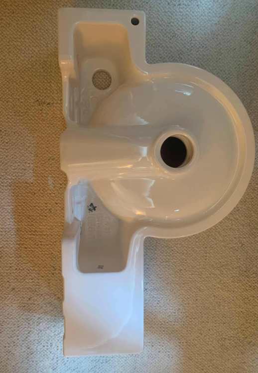
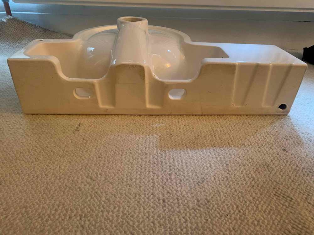
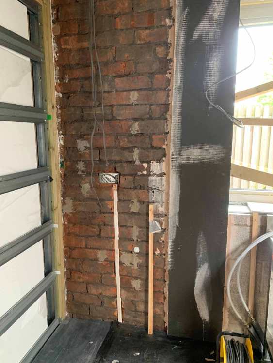
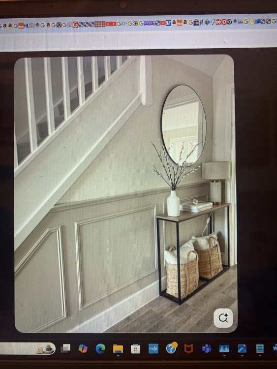
I will need to run pipes through a wall to feed a basin mixer tap. The basin is wall mounted with no vanity unit below, so needs to be done in an aesthetically pleasing way. Ideally the pipes would be almost hidden close to the underside of the sink. However I am seeing photos like the one attached were the pipes are brought through near the waste pipe which puts them on display - looks ugly. How close to the tap can the pipes be brought through the wall ? I will be using the basin with offset bowl and an off centre tap.
-
I have bought a Kemper Frosti Tap from the German Amazon site. (Not fitted yet)
-
How best to cable for Washer and Dryer ?
Spinny replied to Spinny's topic in Electrics - Kitchen & Bathroom
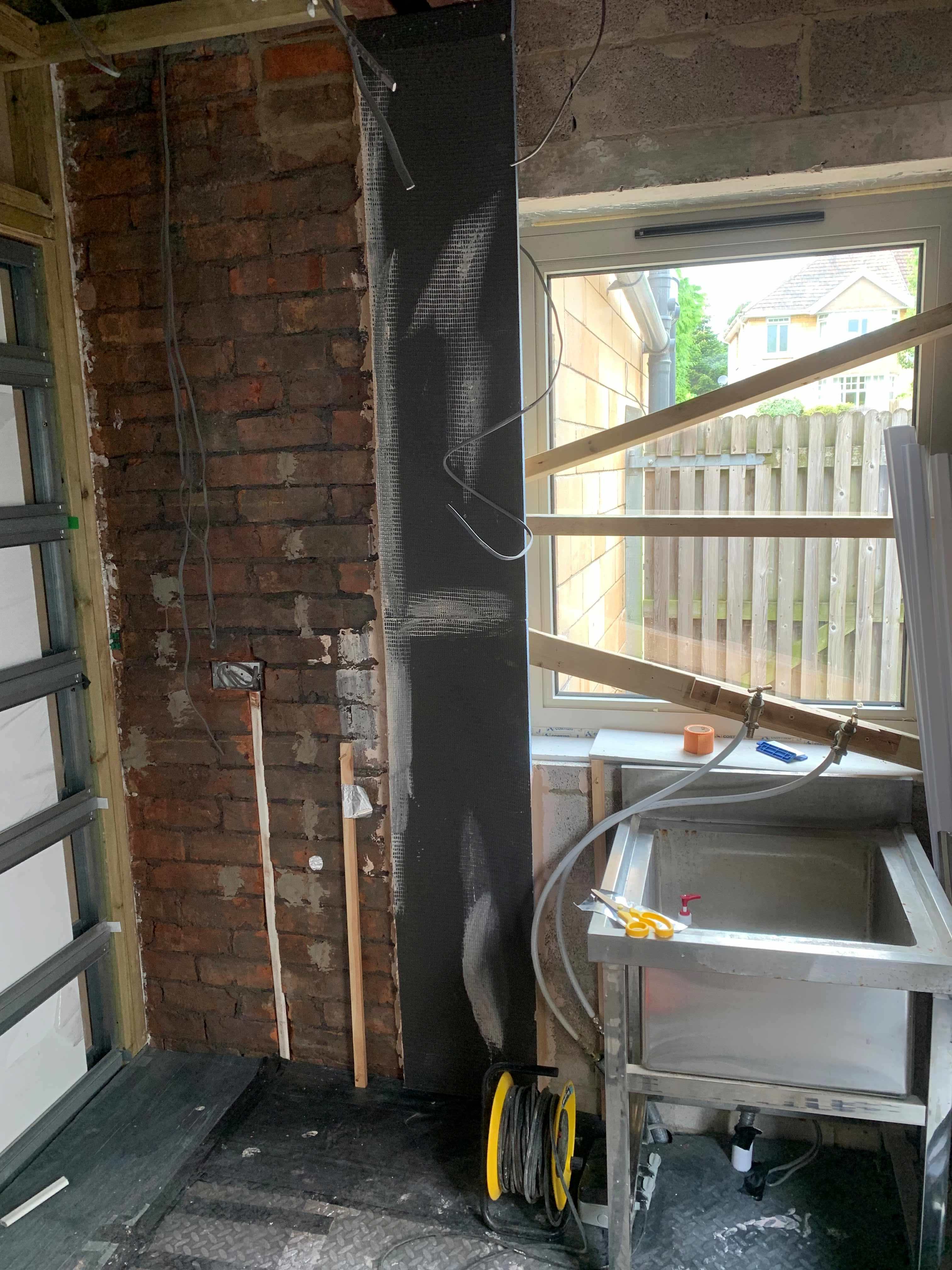
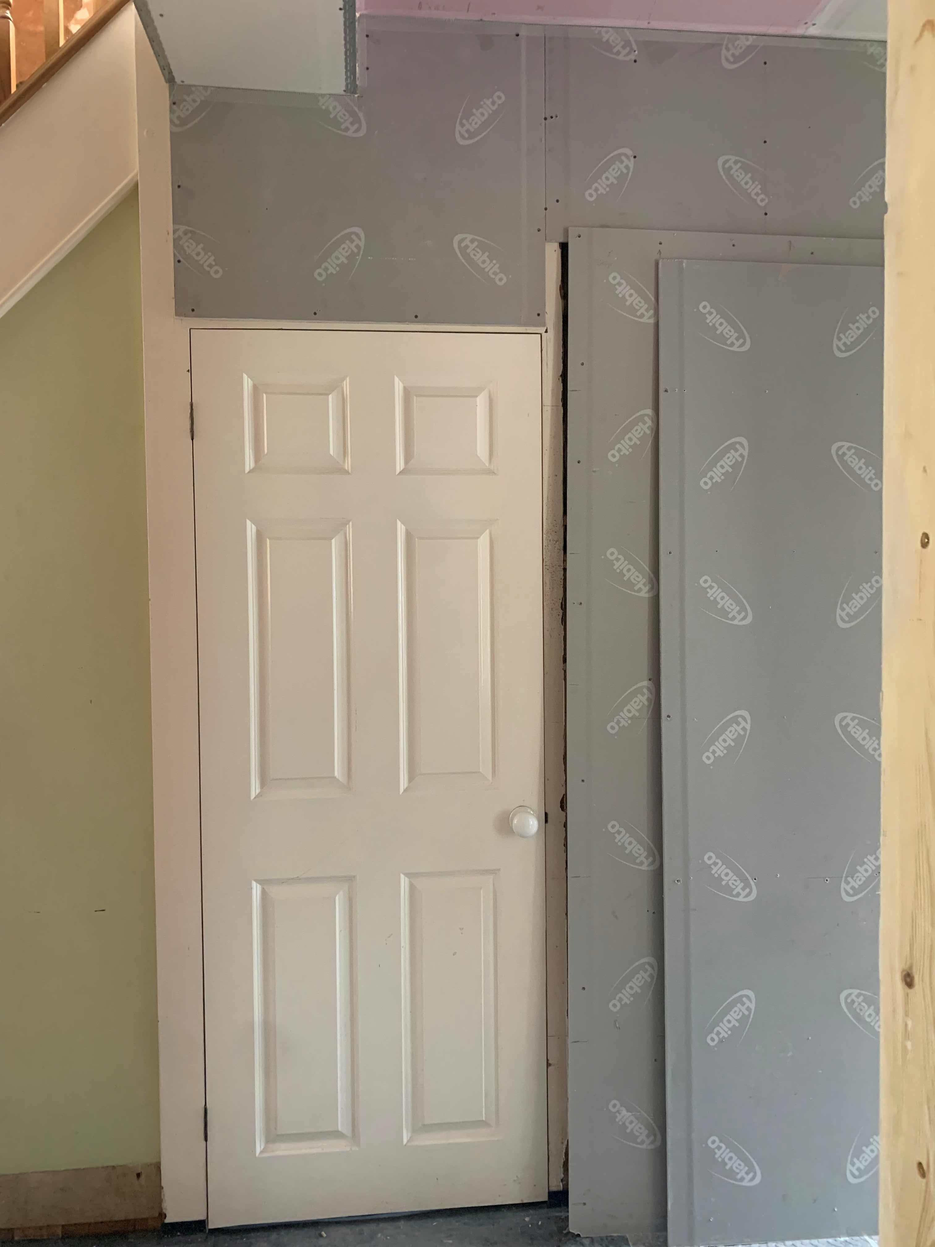
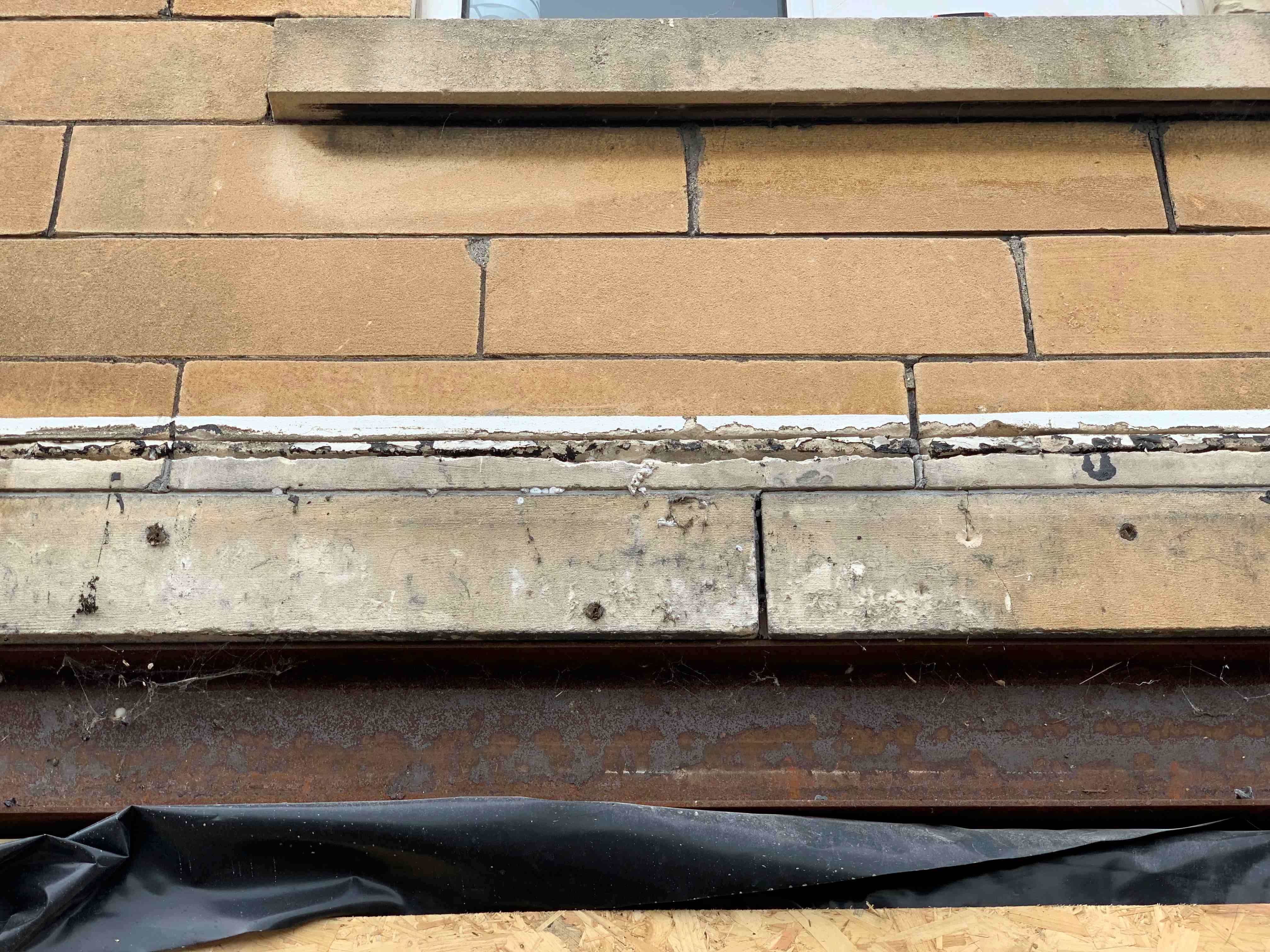
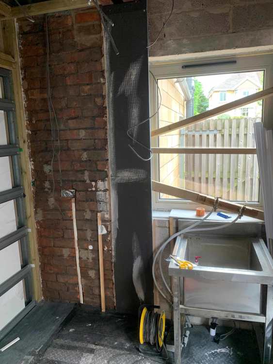
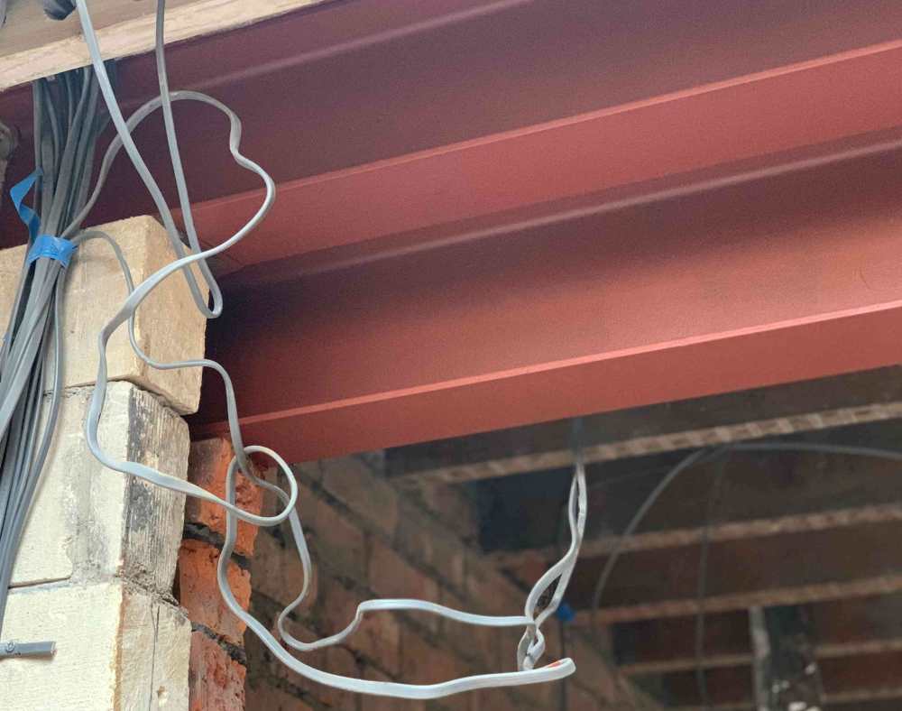
Pictures... Silver circle is approx position of waste pipe to come through the wall from the u/stairs basin. Silver square approx location of water pipes to go through the wall to the basin. two wooden sticks show approx position of the washer bay and the dryer bay extent. Cables down wall are switched live and live for switch in the wall cupboard for the extractor fan. So need to 'solve' routing for the plumbing and for electrical sockets for the washer and dryer - drain is located underneath the sink. I think a grid switch to turn the washer and dryer sockets on/off somewhere would be nice - would have to come off the ring main ? A washer seems to be up to around 2.5kw or 11A, and a dryer either 12A for a condenser or 4A for a heat pump. Do people still use a stand pipe for the washer plumbing, or directly connect it into a waste pipe to the drain ? And should the same waste pipe be used for washer and the u/stairs basin ? waste pipe would occasionally block with gunge on our old one.
-
Hopefully you don't live in the very east of Russia ? Consider asking the spouse to sleep in the back bedroom ? More seriously I notice damp/moisture meters are quite cheap on Amazon. Maybe buy one so you can check out the moisture levels in different parts of the walls. There is probably someone that could do a drone survey of the roof valley ? Have you filled and repaired the plaster in the past ? Any clues from the timing of when the cracking appeared - e.g. after prolonged wet period, after prolonged dry period, after putting your two mega-tonne anti-gravity device in the back bedroom etc. Does the conjoined neighbour have a similar problem ? Is that what used to be a quarter landing at the top of the stairs ? So the bottom of the crack is starting where the rear extension was added ? Do you know where the lintels were positioned for the rear extension ?
-
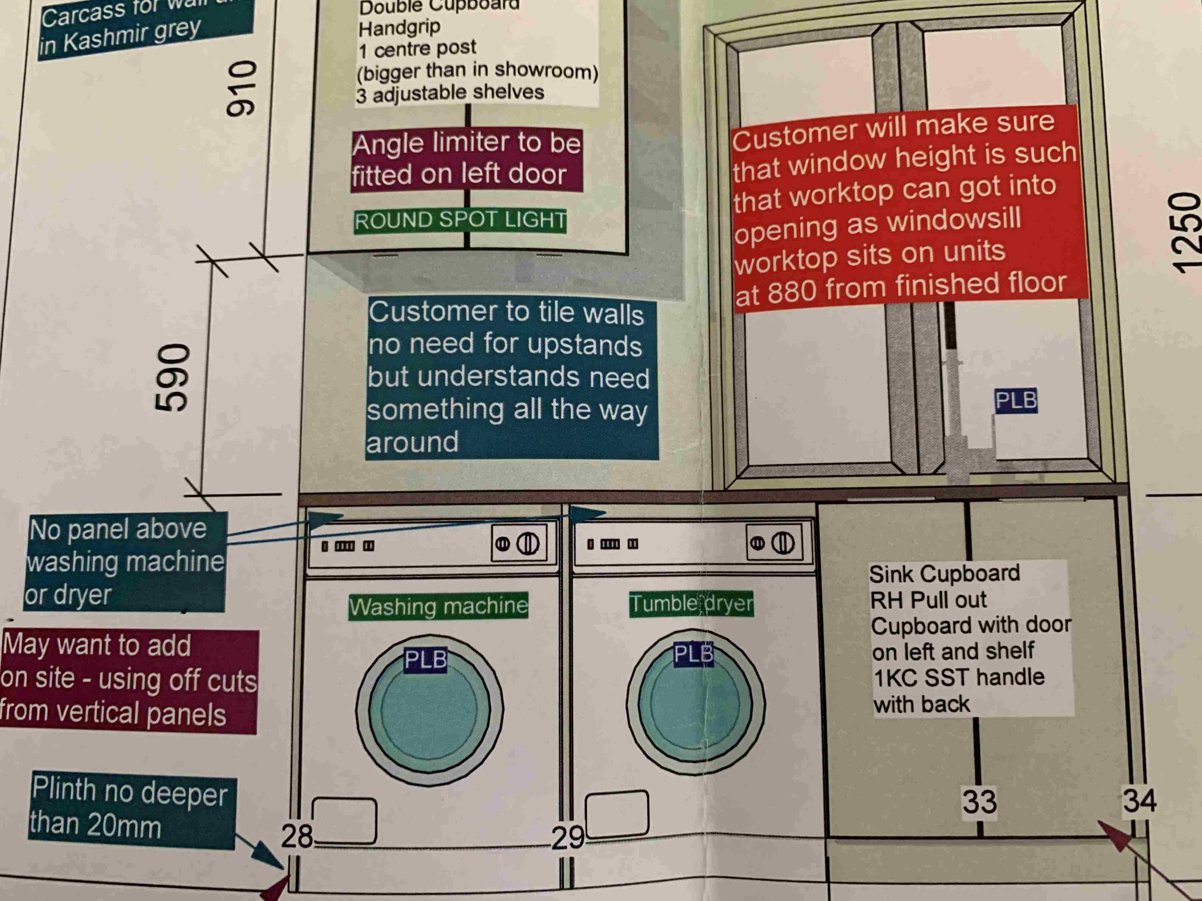
I plan to put a w/machine and dryer alongside each other in a utility room. They will be under a worktop but not integrated. There will be a wall cupboard above the worktop. There will be one double power socket above the worktop and appliances. Sparky originally advised there was no need for any fused spurs or remote switch, a double socket could be installed under the neighbouring sink unit and the appliances plugged in there. However the more I now think about this the less I like it - appliance cables may not be long enough - may restrict pulling an appliance out - will restrict under sink cupboard space - not good if integrated appliances are fitted later etc. What is the best or normal layout of sockets, spurs, switches etc for this situation ? Do I need to put some more cables up and down the wall now before the plasterer gets there ? Put switches inside the wall cupboard ? Thanks.
-
Get rid of the bath taps - use a bath filler at the bath overflow. Who wants to bang their legs on taps while showering. Also no taps makes room for a bigger bath. Shower on the non-window side with a fold out shutter to block off part of the window ?
-
What level of detail in BC tech drawings?
Spinny replied to flanagaj's topic in General Self Build & DIY Discussion
Our architect did a drawing showing the drainage layout and services/extractor positions as part of detailed design. The structural engineer did a report with the joist/steel/lintel dimensions and layouts, structural calculations for them, foundation and slab specification etc. We had test pits dug to assess ground conditions. I am not sure building control pore over it too much if they can see you have professionals on board. In reality it doesn't become fixed in stone. We had two lintels changed from concrete to steel during build, and just sent the new specification and calculations for these from the structural engineer to BC. -
Thoughts on proposed layout for self-build
Spinny replied to Ben Brewin's topic in New House & Self Build Design
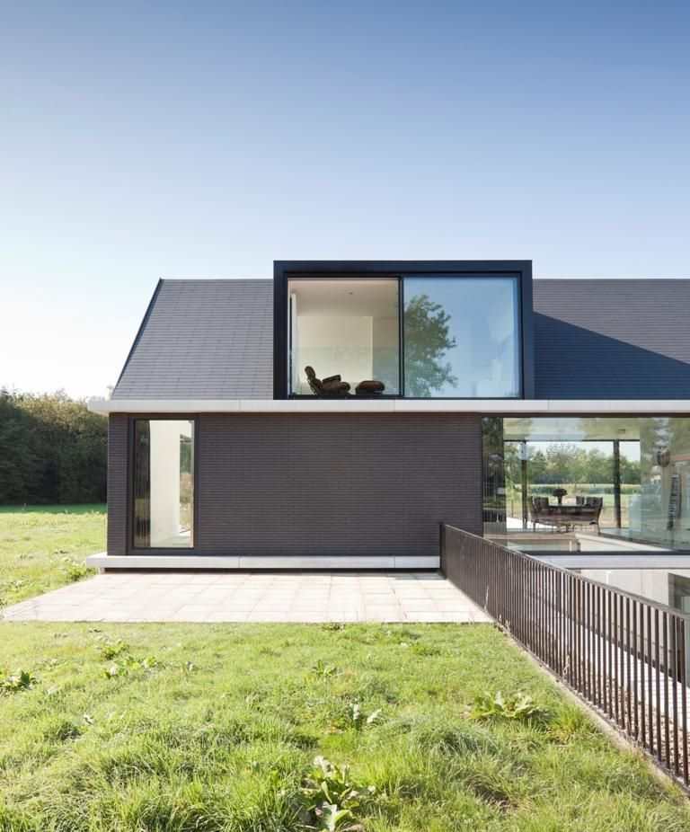
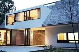
Looking again I am surprised the upper floor doesn't feature at least one dormer window. There appear to be only 3 windows serving the upper floor and all of them positioned in a gable end. No velux or rooflight windows there either - just 3 windows. Given all that tiled sloping roof I'd be thinking at least 1 dormer. My late parents had the upper floor in the roof and ended up installing double dormers opposite each other in both legs of the roof which made a huge difference. Dormers can look old fashioned, but a decent architect would avoid that. PS Open plan kitchen diner looks sizeable and perhaps likely to be used as a second seating area too - so where would the ubiquitous second tv go ? Maybe think about the kitchen/dining/seating layout in there carefully - the layout is likely to strongly influence the electrical/lighting plan for that room. PPS Looks like the original architects might no longer be ?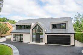
-
Recommended manufacturers or Installers in the South West?
Spinny replied to Lears's topic in Windows & Glazing
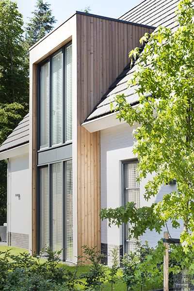
We used two different supply/installers so that we could get particular bifolds and large adjacent windows from one company, and then single doors and windows from another. Just because we wanted particular bifolds but didn't like their single doors. It is all RAL coloured aluminium so all looks fine together with squared off profiles etc. Going to a big home improvement show gave us a chance to look at some offerings, and then off to their showrooms. A lot may depend on your priorities re cost, quality, timeline. When you have openings and they come to measure up, get them to mark a reference level clearly at multiple points on your walls e.g. 1m above FFL. And give a lot of attention to how the same floor level is going to be achieved between the extension and the existing building by the builders. Overheard our builder telling multiple customers 'Sorry the floor level is a bit off but a threshold/small step will cover it up' and we had to change our internal flooring plans because of such a problem. Ask about threshold and cill options. -
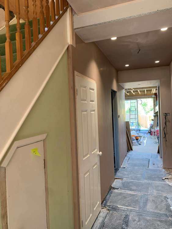
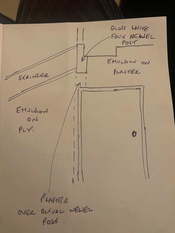
It has been skimmed now see pics. Quite happy with the way it has turned out, much better than some of the other ideas bandied about which involved having parts of the gloss white newel post on show lower down the wall. I do agree with Nick that some added molding is likely to finish it off. The horizontal timber along the edge of the upstairs landing has also been boarded ready to plaster, so elected to run the faux newel piece added to the front of the actual newel up as far as the top of the stringer as that seems like a structure related logic for where to end it.
-
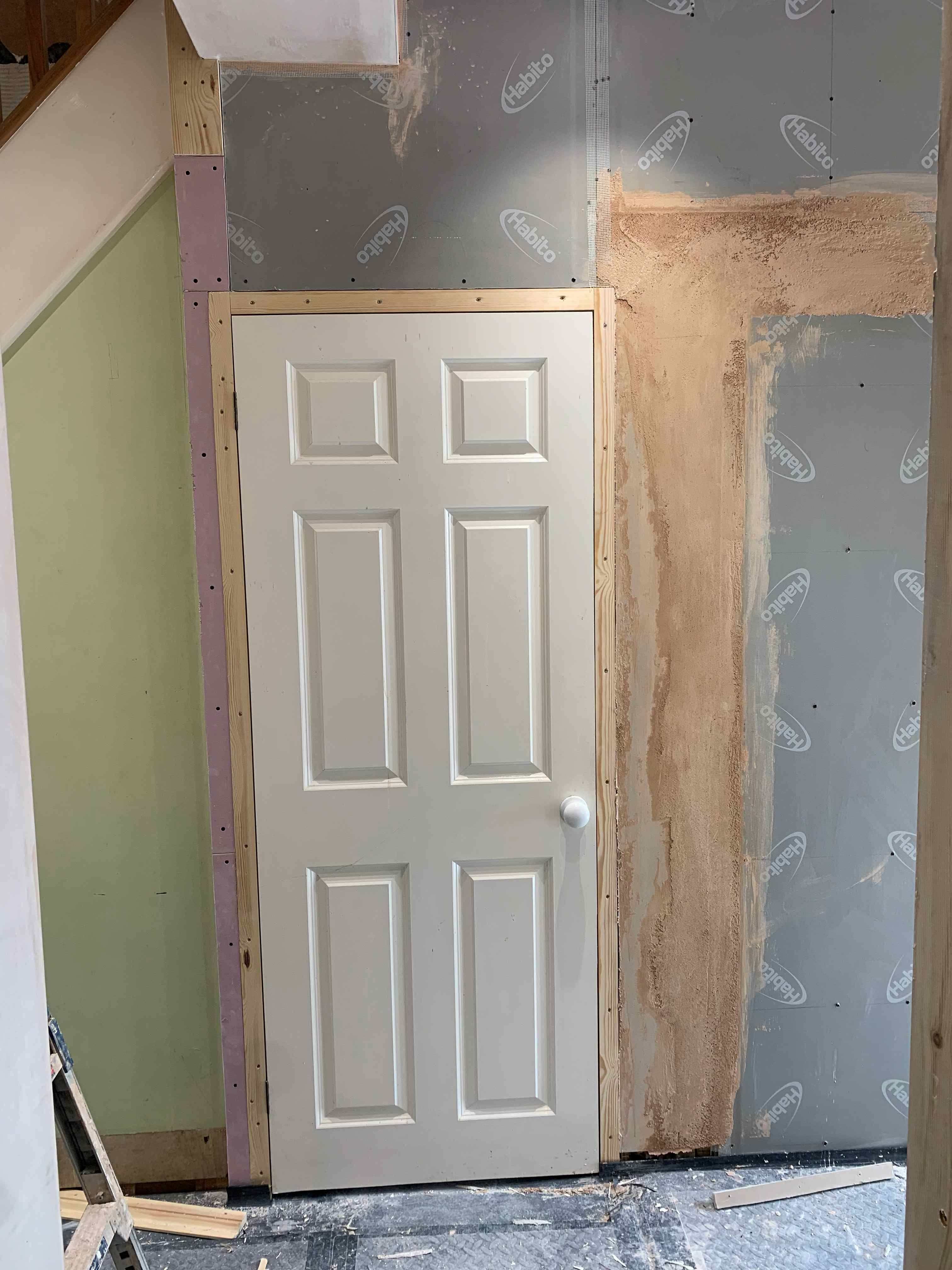
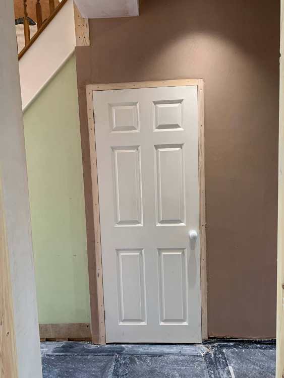
ah ok. Just looking for a way to get the whole area around that door to look right when architrave is put around the door and it wasn't clear what to do with the newel post coming down. carpenter was suggesting I would have to put gloss paint on one edge of the newel post and then matt emulsion on the other face. But I think boarding and plastering over the newel post is going to work better. Now under way - see pic.

-
Thoughts on proposed layout for self-build
Spinny replied to Ben Brewin's topic in New House & Self Build Design
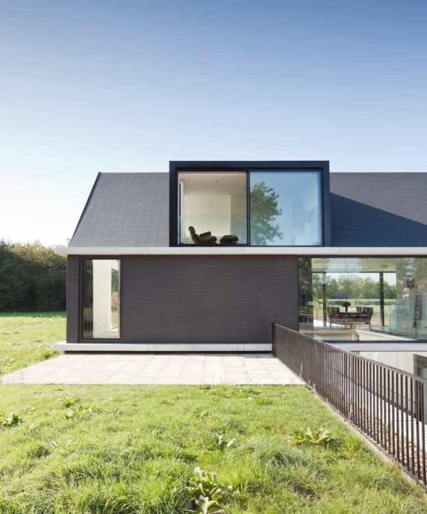
The traditional way of increasing the area of higher ceiling height in rooms in the roof is the dormer window of course. I notice how appropriately positioned velux windows can achieve a similar effect by using the window reveal to similar effect. Wonder if some adjusted toilet/services layout around the entrance way might allow the front door to be moved across to better align with the double doors at the back of the house to give you that 'look right through the house' look when you come in through the front door. Timber cladding looks wonderful when new, but we decided we didn't like the aged grey look so much so went with Cedral fibre cement boards instead. Agree with Pro Dave about access from the other road. Also back of house currently faces east, so evening sun will be at the front of the house and the back will be shaded by the house itself at that time. Consideration might be given to rotating the house by 180 degrees and then flipping the across the midline. Size and position of existing trees also to be considered. There are tools you can use to examine the passage of the sunlight over the property. (We are east facing at the back but by having a roof light in the side extension we can catch some evening sunlight, and fortunately the garden length and angles work to give us evening sunlight). -
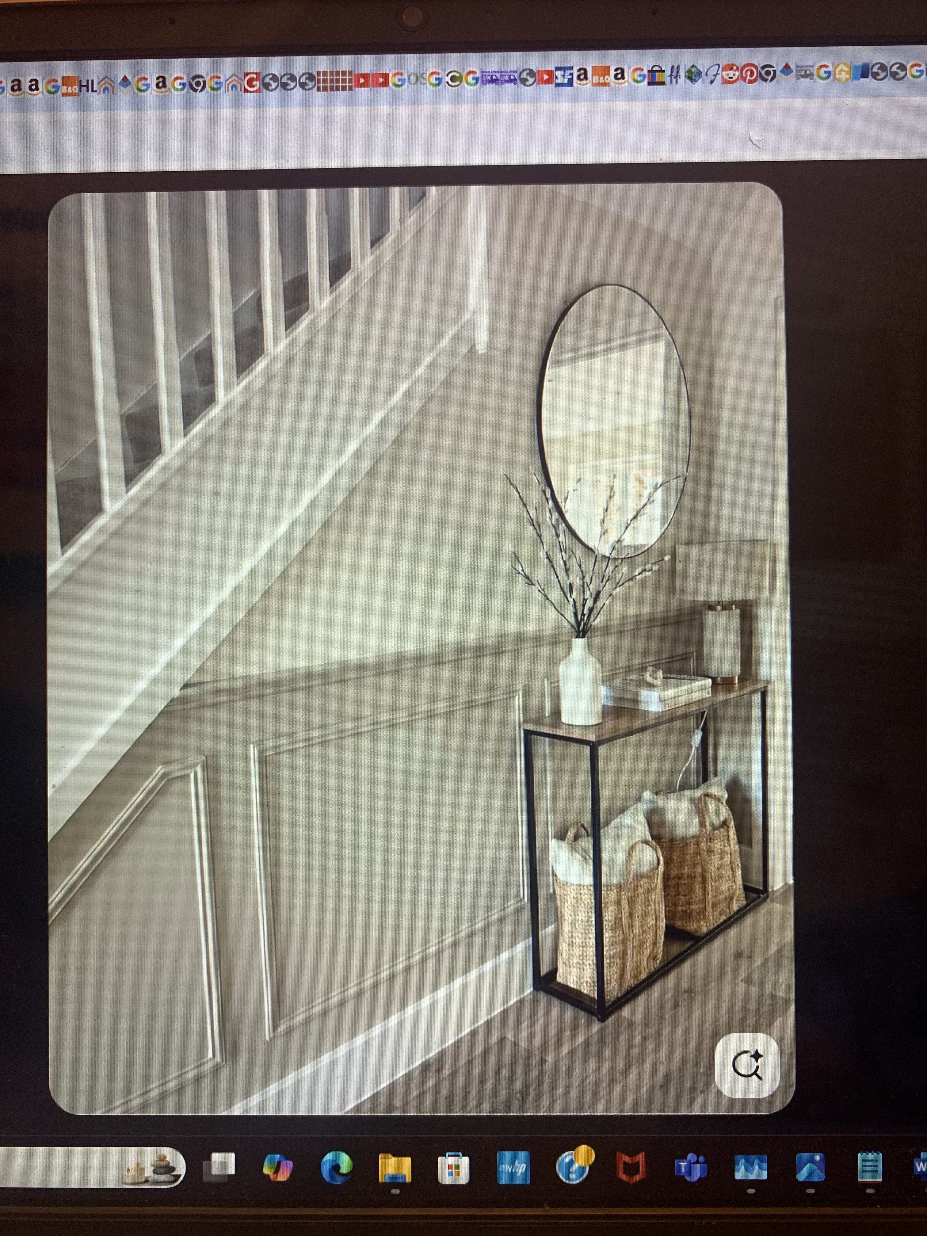
Hi, urgently trying to find a decent aesthetic way to finish around my understairs door and wall. I am wondering about boarding and plastering over a newel post running up from ground floor to first floor, but then creating a 'faux' floating newel post at the top of the staircase stringer. See photograph and sketch. The aim being to resolve details around the doorway and allow an architrave to be fitted around the understairs toilet door. Do people think this idea will work ? Any other ideas for making the area look decent around the door area and surrounding hallway wall ?

-
Wow, is that really going to work for the life of the doorway - the screw holes will end up practically on the join. (In the youtube i watched people were not moving the hinge and accepting of a rebated door front, but personally in a hallway directly adjacent to other doors I don't want to do that and have it look odd.) Most times if you have a problem that could be solved by a suitable hinge, someone has already invented it, the only problem is finding it - he said hopefully, having been too busy phoning eclisse over my pocket door issues to further trawl t'internet.
-
Strewth. They are going to kill us all for dollar... https://www.youtube.com/watch?v=SC2eSujzrUY
-
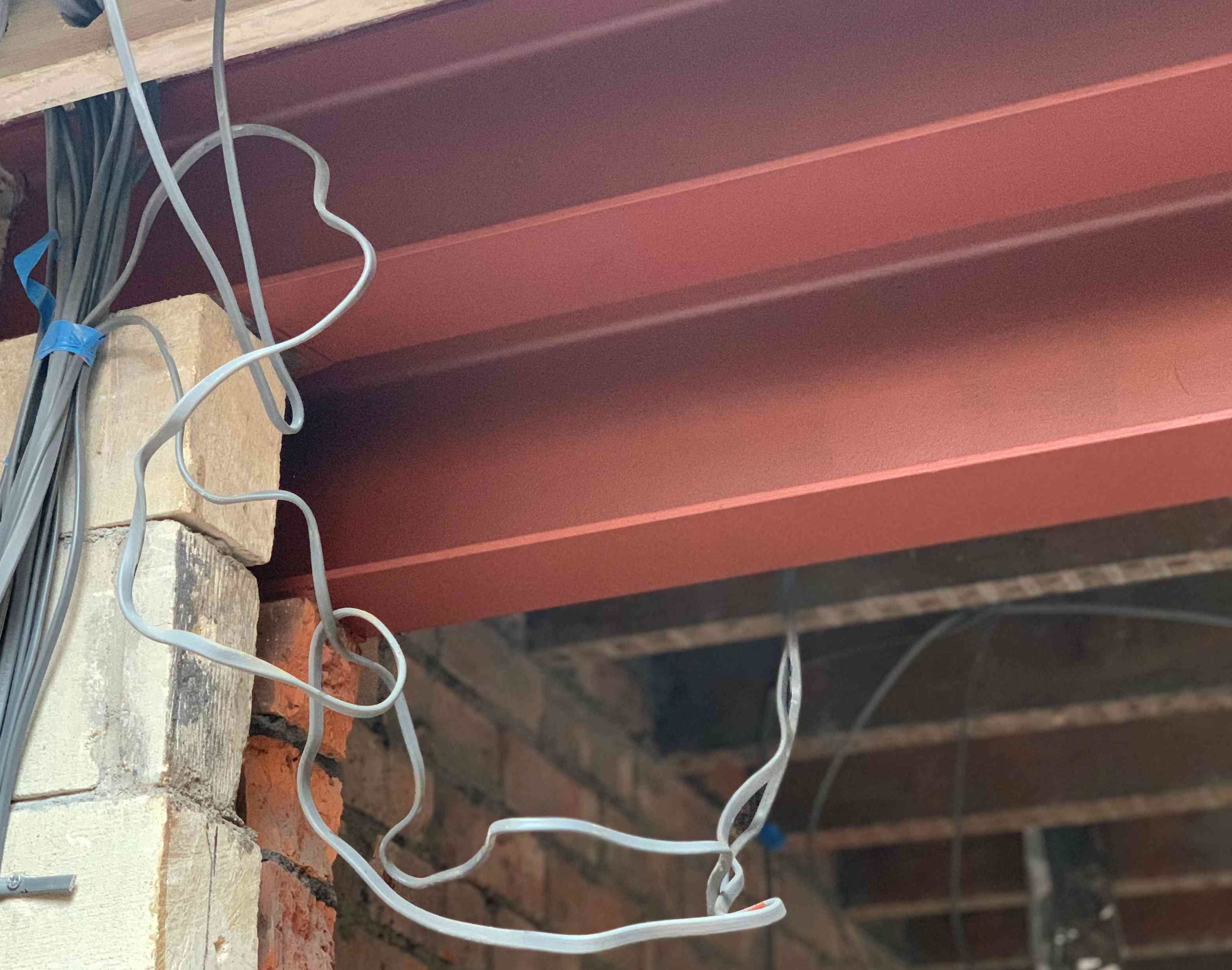
Your comment made me check - My mistake apologies, I was misremembering from 2 years ago... Structural Engineer did NOT recommend intumescent - he actually recommended Zinc Phosphate Epoxy and I bought some from here https://www.taindustrialpaints.co.uk/products/two-pack-epoxy-high-build-zinc-phosphate-metal-primer - it is two part and you have to mix in a catalyst. When it arrived it had loads of health and safety and storage requirements so I didn't use it, and went with the red oxide.
-
Has got 15mm fireboard underneath. Got a call in with Building Control.
-
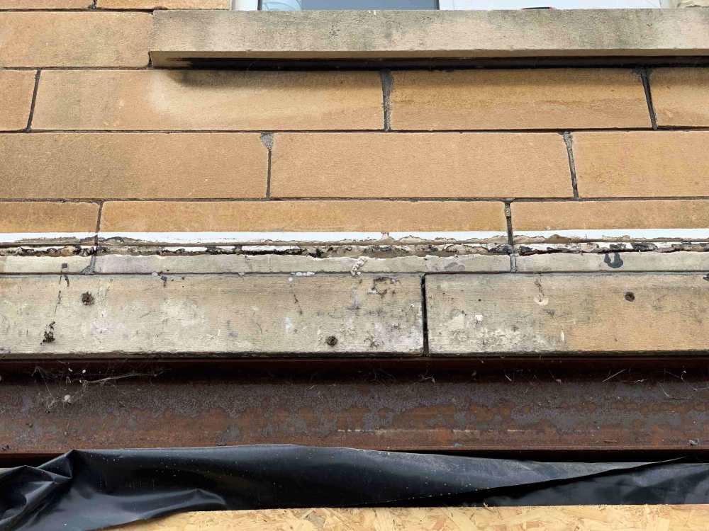
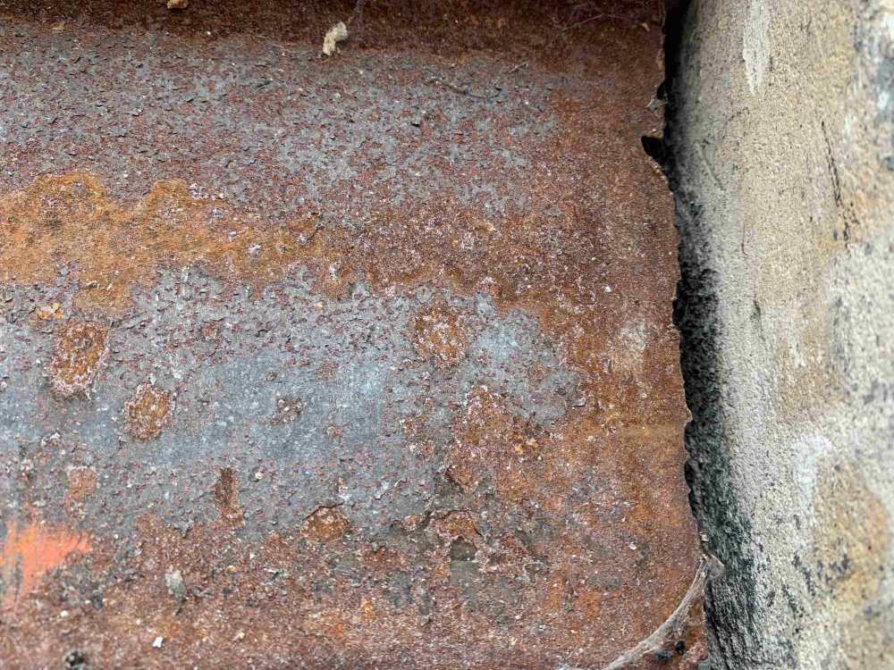
We had the same with steels that had been in place about 42 years (see pics). I had our structural engineer take a look, he gave them a good poke with a screw driver and said they should be fine for another 100 years, vigorous wire brush (as you propose) and treat. He suggested an intumescent coating paint, but when I got some delivered the skull and crossbones warnings all over the stuff made it seem you would die if you opened the can. So I went with vigourous wire brushing/drill attachment, then treatment with Neutrarust 661 (NATO approved rust convertor for use in ships, tanks etc - available on Amazon), then 2 coats of iron oxide paint. Photo shows the end result. Builder showed zero interest in doing anything to the steels so I had to do it myself.
-
Plaster boarding going around a steel. The steel supports a 2.2m opening in the back wall of a 2 storey house. Wondering whether the fire protection requirement (would it be 30 mins or 1 hour ?) can be met with a 12.5mm fireboard. ? The problem being that the rest of the wall has already been boarded in 12.5mm, so using 15mm will create a problem with skimming the wall. There is 70mm of rockwool between the 44mm studs in front of the steel and therefore immediately behind the plasterboard.
-
Yes, have seen a youtuber doing that too. However it doesn't move the hinge point forward so the door face doesn't move forward.
-
Interesting, would like to see a photo of that. Lighting is a tricky thing. Architects don't seem to address it - ours just asked us to come up with a lighting plan. Then you are thrust into the world of lumens per square metre, CRI, CCT, LED tape, beam angles, baffles, smart control etc. Once you see the space you change your mind. Think I have over 20 switcheable lighting groups now.
-
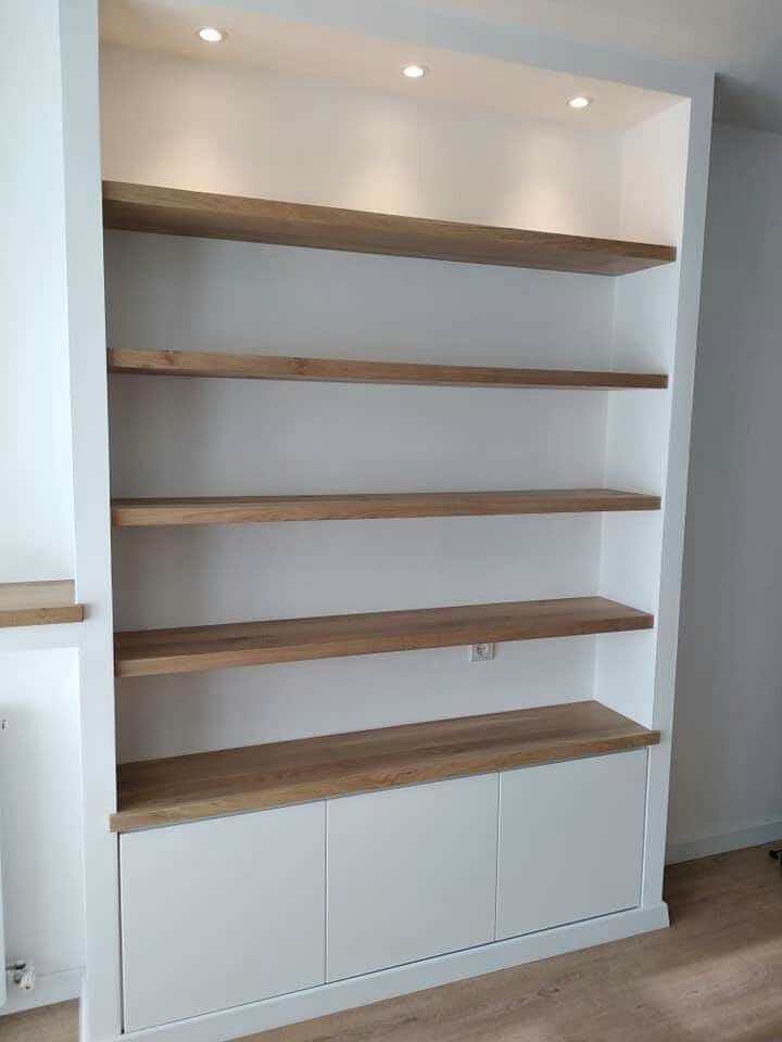
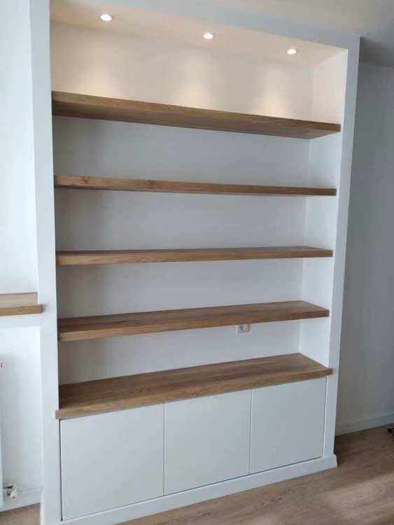
I am not sure about the back lighting, I guess ideally you might have both, but we are not planning anything other than a white wall behind at present. I have also seen them put facing upwards at the back of the shelf. It is good to see pictures of actual install like yours, thank you. Now thinking of putting a couple of baffled mini downlights into the downstand as has been done in this photo. (PS I have got some trunking put in running up the wall behind the plasterboard at the side of the recess so I can just drill into it and fish the wires through. Then as we are having a cupboard at the bottom I have had a cut out left in the plasterboard with a plywood board behind to fix the transformer and WLED controller onto. Thinking of putting addressable cob led strips in everywhere just for the hell of it.)
-
I have an alcove 250mm deep we will be putting in a cupboard 90cm high then shelves above. At the top of the alcove we want to box the ceiling down a little in plasterboard to give that 'built into the wall look'. Question is if we put LED strip under each shelf (probably oak look shelves) - should we put led strip into the underside of the plasterboard downstand ? (i.e. to light the top shelf) Thinking LED strips should go near front of shelves.