John Carroll
-
Posts
577 -
Joined
-
Last visited
-
Days Won
3
Everything posted by John Carroll
-
Its passing, gland fine, water is perfectly soft. I also have a few gate valves, ~ 20 years old around the place which don't pass a single drop of water.
-
I had a inside 1/2 ins (+NRV) isolating gate valve on a supply to a outside hose used to wash the car, after ~ 45 years I decided to splash out and installed a 1/2 ins (reduced bore) ball valve, this valve is either just fully open or fully shut say once/week. After around 4 years this valve started leaking slightly so I just replaced it with another ball valve but, this valve is again leaking slightly after 3.5 years. My mains pressure is a very constant 3.4/3.6bar. Do all ball valves behave like this?
-
Stuart Turner Negative Head 3bar Twin
John Carroll replied to John Carroll's topic in General Plumbing
I'll just leave it at that. 😀 -
Stuart Turner Negative Head 3bar Twin
John Carroll replied to John Carroll's topic in General Plumbing
I doubt if theres any requirement for balancing, the positive head pumps don't have any connecting pipe I think. I wouldn't have any big worries with a shower where the HW is say 60C and the cold 10C, you need 9LPM at 60C mixing with 6LPM at 10C to give 15LPM at 40C, the hot might be reduced to say 50/55C by dilution but no problem for a thermostatic shower, however if say running the HW cylinder at even 50C where you the require 11.25LPM of hot mixing with 3.75LPM of cold to give 15LPM at 40C, this might well result in significant dilution to then cause shower temperature control. People with ASHPs and vented HW cylinders probably often run with a cylinder temperature of 45C or even lower, this might result in a HW temp as low as 35C, not too pleasant for either showering or normal kitchen use. Anyhow, all it requires is for someone with one of the hundreds and hundreds of these pumps to run a few tests at different flow rates and temps, that will soon put all this to bed, hopefully not in the way I fear it might. -
Stuart Turner Negative Head 3bar Twin
John Carroll replied to John Carroll's topic in General Plumbing
Just spoke to someone in Dublin who overhauls/reconditions these (ones with the 15mm connecting pipe) and he confirmed that the pipe has no reduced ID O rings etc, the only restrictor is the 4.1mm ID O ring where the pressure vessel is mounted on the T piece, the schematic shows 15MM ID O rings at either end so certainly looks like a unrestricted 15mm piece of pipe between the two outlets, extraordinary, and IMO can only result in dilution, varying from very little if both sides puming similar volumes of water to pretty hefty dilution is only hot or cold water required from one end.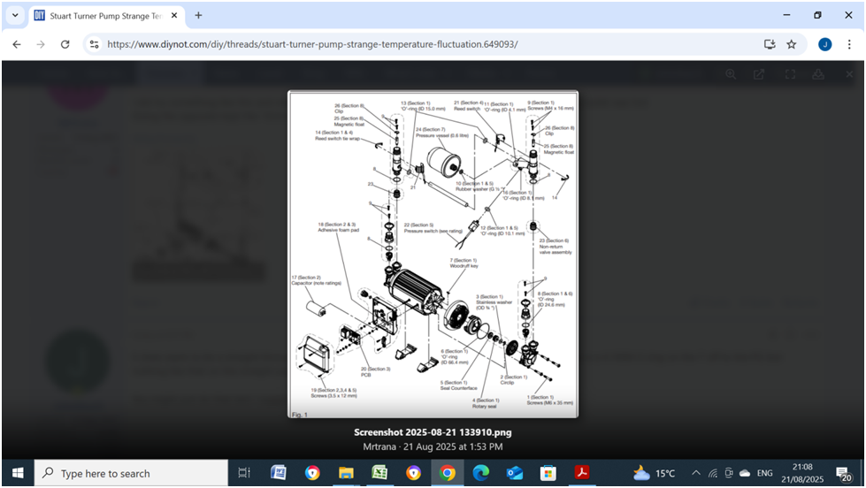
-
Stuart Turner Negative Head 3bar Twin
John Carroll replied to John Carroll's topic in General Plumbing
There will always be two flowswitches, the one pressure switch may be on the system as described above or there maybe just the pressure vessel+pressure gauge taken off one outlet end, in which case the pumps are completely and properly isolated from each other. Have you got a link to that schematic above that shows a outline of the pump associated with it. -
Stuart Turner Negative Head 3bar Twin
John Carroll replied to John Carroll's topic in General Plumbing
Yes, Alan, that was my immediate thought, it would seem utterly bizzare if the pump is constructed as shown. ST asked the owner to check that both NRVs were OK, which they were, ST then said the problem could be due to Xover in a mixing tap, tests were carried out, there is/was no X over. That piece of 15mm short pipe, say ~ 500mm long will only have a friction loss of well less than 0.1M at a flow rate of 7LPM, so, in the context of the pump flowrates, almost a full by pass, if unrestriced or controlled in some manner. Do your pumps have this single piece of pipe with the PG & pressure vessel mounted on top?, I have seen some types of negative head stuart turners with two pressure switches and two pressure vessels and also I think some with just one pressure switch and one pressure vessel mounted on just one side, presumably expecting that hot and cold water are both required. Could you please post a photo of one of these pumps showing the pressure vessel/pressure gauge etc. and maybe carry out the hot/cold only tests sometime. -
Has anyone noticed any problems with this type of pump where the cold outlet can and does get warm/hot and the hot outlet goes cool depending on whether more hot or cold water is required, this is because the hot and cold outlet are directly connected with a short piece of 15mm (~ 13mm ID) piping on which the pressure vessel & pressure switch are mounted, this, in effect, means you have two pumps running in parallel, with no control over the hot/cold mixing, this is a brand new pump, the owner took the discharge ends apart to confirm that there was no orifice plate in this piece of pipe, despite this ST would not admit that there is a apparent problem with this design, luckily, he found that a positive ST pump is quite adequate for his requirements and returned the above pump. I know this sounds almost unbelievable that no orifice of say 1.0/1.5mm is installed in this bit of pipe which would still allow the pressure switch to operate properly but only allow say a "bypass" of ~ 0.2LPM which wouldn't cause too much dilution even though not ideal especially from a renowned outfit like Stuart Turner. If you want to test the above, just open a cold tap only for a few minutes and see does it then run warm/hot and then open a hot tap only and see does this then run cool, the connecting bit of pipe should run either very hot or just cold during these tests. Stuart Turner Schematic.docx
-
I defrost the above every 4 weeks even though its not iced up. Normally, (via a plug in Energy monitor), when it cuts in the power demand is 90W to 100W and just before cut out, is 83W, this cut out at a indicated 83W is very consistent but after a defrost the compressor will still run for hours (normally, 45mins) even though the power demand is down to 73W/75W and the fridge&freezer are both ~ 3C/5C colder, this is with the same stat setting which I keep at minimum, otherwise both would bee too cold, question is, why doesn't the stat open and shut off the compressor at its normal 83W which should pretty accurately reflect that the sensing capillary should open the contacts and should definitely open them at a power demand of 75W?. I also noticed that if I switch off the power supply while its running constantly at 75W and then restore it that the stat has apparently opened and will stay open then for ~ 30/45 mins and restart with a indicated power of ~ 95W. If I then leave it run for say 20 minutes or so and kill the power and then restore it, then, as expected, the compressor will immediately restart.
-
Sorting out expansion vessel and overtemperature valve
John Carroll replied to jack's topic in Boilers & Hot Water Tanks
If, (which it probably has been) the EV precharge pressure has/had been set to 3.0bar and even assuming that the cold water pressure after the PRV (set to 3.0bar) never went higher than 2.0bar before reheating then the expansion relief valve would still have lifted if ~ 150L or more of the UV cylinder required reheating to 60C. My ancient spreadsheet, below, may be of interst and be a help in sizing calculations for either HW or CH. EV CalcsJK Rev0.xlsx -
Sorting out expansion vessel and overtemperature valve
John Carroll replied to jack's topic in Boilers & Hot Water Tanks
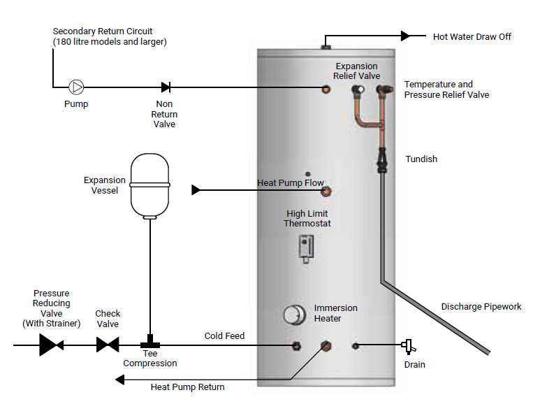
From the horse's (McDonald Water Storage) mouth, the MI's show, below, the expansion relief valve mounted on the cylinder as yours is and none on the valve set (again like yours), the PRV should be set to 2.1bar, likewise the EV charge pressure....set to 2.1bar and that's why a 22L EV is perfectly acceptable under those conditions, a full reheat to 60C then gives a final pressure of 2.8bar, 65C gives 2.91bar & 70C gives 3.12bar. all comfortably below the expansion relief valve's 3.5bar setting. ECOFlow-Installation-Manual.pdf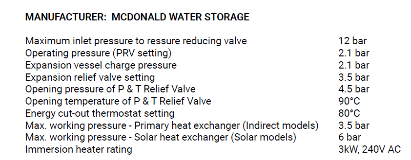
-
Sorting out expansion vessel and overtemperature valve
John Carroll replied to jack's topic in Boilers & Hot Water Tanks
You said the EV was flat, what pressure was it recharged to?, it should also have been done at the very least with the cold mains to the cylinder shut off and a HW tap opened, if its located above the cylinder then that should be OK. I would also suggest checking that there is a pressure reducing valve (PRV) installed (which there should be) on the cold water valve set and most/more important that its setting is checked. Even with your 22L EV and assuming that you will rarely if ever be reheating a full cylinder, more likely say 80% or 200L then a final pressure of 3.12bar at 60C & 3.25bar at 65C with a cyl prepressure of 2.3bar, 2.5bar (if available) will still give over 90% flowrate of a 3.0bar cylinder. Is the blue PRV next to the (red) TPR also stamped as set to 4.5bar? -
Sorting out expansion vessel and overtemperature valve
John Carroll replied to jack's topic in Boilers & Hot Water Tanks
(If) You wish to retain a 22L EV with the pressure reducing valve (PRV) set to 2.5bar, at this setting and with a EV precharge setting of 2.3bar (ideally) then after a full reheat to 60C the final pressure will be 3.35bar, and if reheated to 65C will be 3.49bar, both too close IMO to the expansion valve setting of 3.5bar. If you reduce the PRV to 2.0bar and the EV precharge pressure to 1.8bar then the final pressures become 2.74bar at 60C & 2.86bar at 65C. If you install a 35L EV then with the PRV set to 2.5bar and EV precharge at 2.3bar will result in a final pressure of 2.99bar at 60C & 3.06bar at 65C, (and still OK at 3.19bar at 70C). If you require a UV cylinder pressure at the "normal" 3.0bar then you will require a EV vol of 65L with the PRV set to 3.0bar and a EV precharge of 2.8bar to give comfortable final pressures of 3.28bar at 60C and 3.32bar at 65C. -
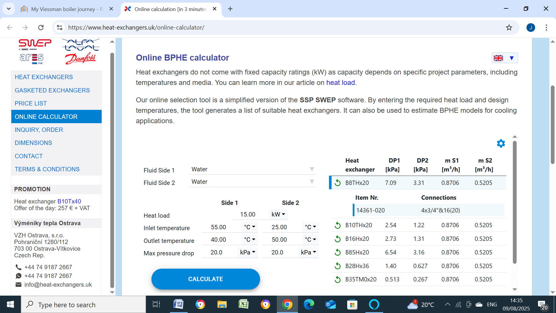
In that case above, then a B8X20, almost 0.5m2, will output a minimum of 15kW with boiler flow/return temps of 55C/40C at a boiler flowrate of only 14.5LPM/0.87M3/hr & secondary side inlet/outlet temps of 25C/50C at a flowrate of 8.7LPM/0.52M3/hr, to heat 115L from 25C to 50C in 25 minutes assuming the cylinder stat is located just above the cylinder outlet to the PHEX inlet.

-
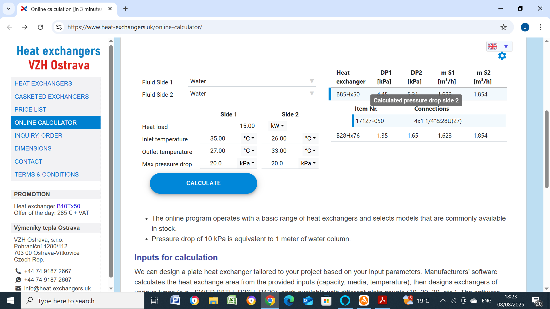
I'd definitely agree that a E8TH x 20, approx 0.6m2 heating surface would be pretty useless in getting a close approach temperature for you, I don't know why the manufacturers specify these (20)kW etc ratings which only apply at extremely high dts at something like 40C. As stated above the bigger (within reason) the better. Here is one that should give 15.0kW output with a approach temperature of ~ 2C, its a B85H x 50, 3.13M2. which might suit your conditions, if you select price list you can calculate the heating surface for any required PHEX, they also seem to suggest a B28H x 76, at 4.75M2. Its probably best to email your requirements to them and possibly to Nordic as well as UK Heat Exchangers.

-
Expected In House Usage of Solar PV Output
John Carroll replied to John Carroll's topic in Photovoltaics (PV)
Based on my usage pattern of a base load consumption of ~ 1.6kWh between midnight and 0800 and 1.6kWh between 1800 and midnight, total (extra) import of 1168kWh/year, I would be quite happy with those possible savings below. It would be interesting if someone with the same usage pattern could post their import/export numbers, mine, where (if I installed a 4mWp)the generated output is ~ 10% greater than the demand shows a ~ 50% import/export and ~ 24%/63% with a 6mWp. 4mWp Solar Output 3820 kWh Consum. 3515 kWh Solar Input 1789 47% Import 1726 45% Export 2031 53% Elec cost €0.34 /kWh FIT €0.21 /kWh Saving €1,035 Yearly 6mWp Solar Output 5730 kWh Consum. 3515 kWh Solar Input 2145 37% Import 1370 24% Export 3585 63% Elec cost €0.34 /kWh FIT €0.21 /kWh Saving €1,482 Yearly -
Expected In House Usage of Solar PV Output
John Carroll replied to John Carroll's topic in Photovoltaics (PV)
PVGIS shows me (around the Kent area) a PV output (6kWp)) of 795.89kWh with a solar radiation of 164.85kWh/m2, this gives a factor of, 795.89/(6*164.85, 0.8047 which seems bout right. The solar radiation in Cork was a monitored 193.96kWh/m2 (May) and I would think that Kent in that brilliant month was very similar. So, assuming this, then your PV output might have been 6*193.96*0.8047, 936.47kWh, not too far away from your measured? 993.26kWh. a 6.8Kwp array (even limited to 6) might give 1061kWh. -
Expected In House Usage of Solar PV Output
John Carroll replied to John Carroll's topic in Photovoltaics (PV)
What size system have you got Mike?. -
Expected In House Usage of Solar PV Output
John Carroll replied to John Carroll's topic in Photovoltaics (PV)
I should have been using a factor of ~ 0.81 in my PV output calculations but even though I have a calculation for it in the spreadsheet I had forgotton to set it properly, I went a step further in Rev3 spreadsheet as I used PVGIS and inputted every single months factor by dividing each months PV output by the radiation value, they went (see spreadsheet) from a low of 0.79 to a high of almost 0.85, ironically, the highest factors are (0.847) in January&February and November&December. I think a factor of 0.8 is generally accepted?. The solar irradiation I use is from our national weather people and is the total daily irradiation and not just spot checked, I get it the day after. PVGIS for a 6M array (Cork) shows a yearly irradiation. PVIGS shows a PV output of 5964kWh with a yearly irradation of 1218kWh/m2, my calcs, using the accumulated daily irradiation numbers, shows irradiation of 1036kWh/m2 to give a PV output of 5024kWh from a PV input of 6215kWh, (average factor 0.808). JohnMo's query re very high PV output in May.... PVIG shows May&June as the best months and their number of a daily May PV output of 24.1kWh is closely matched by my 24.6kWh (after I use the correction factor) It would be a nonsense to suggest that the house load is constant so those inport/export/savings numbers will be somewhat less but nevertheless are a reasonable indicator especially since the installed PV of 6kWp is almost double the house requirements of 3315kWh/year. All very interesting indeed, thanks for all your (hopefully, continuing) insights. Solar Array Output Cork 2024 Rev3.xlsx -
Expected In House Usage of Solar PV Output
John Carroll replied to John Carroll's topic in Photovoltaics (PV)
Usage varies between ~ 8.5 & 10.5 kWh/day based on his two monthly bills over the past year or so. -
Expected In House Usage of Solar PV Output
John Carroll replied to John Carroll's topic in Photovoltaics (PV)
Don't know much about it John but I believe providers here (the EU) must offer to buy any exported PV, but don't know if they are required to offer a minimum rate for it. I have seen quotes of ~ €10k to €14k for installation, depending on size and location. -
Expected In House Usage of Solar PV Output
John Carroll replied to John Carroll's topic in Photovoltaics (PV)
His usage is a very constant 3315 kWh pa, 9.08 kWh/day, and usage is all day time so all the big users are on, most only briefly, when the Solar PV should be productive. I have put a few numbers together which might reflect what kind of savings he migh hope to achieve, currency is in Euros. Solar Array Output Cork 2024 Rev1.xlsx -
A few facts/observations first, I have a modest self installed flat(2) plate solar thermal array, and take the daily, Cork, Roches Point irradiation numbers for the past 14 years, the yearly/period numbers change very little from year to year, for example, periods 1/1 to 17/7 for years 2022,2023,2024,2025, are 665,643,663,703 kWh/m2. I also notice, see "10 Panel Solar PV" below, that the panel efficiency appears to change very little between low and high solar Irradiation, the (10 Panel) attachment shows a 2.6kWp system with a area of 16.4m2, the modelled yearly output is 2.454 Kwh which equates to a efficiency of 14.96%, all the monthly efficiencies are pretty close to this, does this sound plausible? my solar thermal efficiencies certainly vary quite significantly, from say 10% to 28%. The real reason I'm posting here is that a neighbour is thinking of installing a 4.0kWp system and possibly a 6.0kWp one if his south facing roof can accomodate it. His yearly demand is ~ 3500kwh, 9.6kWh/day, he has a 9kW electric shower only used for 15 minutes/day, plus, electric cooking, electric kettle and the usual other low power users. The spreadsheet is just my estimation of the output, the solar irradiation are my measured ones. The FIT here is ~ 18P/kWh Would someone venture their openion(s) based on the above, as to what the per centage of self usage might be, based on a 4.0kWp system and on the the 6.0kWp system, or on your own personal experiences. Thanks, John. Solar Array Output Cork 2024 Rev0.xlsx 10 Panel Solar PV.pdf
-
Top Mounted Vertical Immersion
John Carroll replied to John Carroll's topic in Boilers & Hot Water Tanks
If you can move that as far up to the cylinder top as possible and run on the electric immersion and drain down as you say maybe 20/30L to get the stat to cut in, then wait until the stat cuts out, and repeat this test say one or ideally two more times then that will provide the info I'm after hopefully. -
Top Mounted Vertical Immersion
John Carroll replied to John Carroll's topic in Boilers & Hot Water Tanks
Again, thanks, but a horizontally mounted heating element heats the cylinder in a completely different fashion to a top mounted vertical one.