John Carroll
-
Posts
577 -
Joined
-
Last visited
-
Days Won
3
Everything posted by John Carroll
-
Worcester Bosch Anti Fast Cycling
John Carroll replied to John Carroll's topic in Boilers & Hot Water Tanks
I think they are exactly the same as the Vaillant ones. The Set maximum burner anticycle time determines the actual anticycle time. The default setting of 20C means the maximum anticycle time is 20 minutes in the very unlikely event that the target/flow temp is 20C, if (for the same 20C setting) the target/flowtemp is 60C then the anticycle time is only 6 minutes which makes sense because the return&flow temperatures will fall quite alot with the circ pump continuing to run so gives the boiler better leeway to get away on refiring and prevent the burner to trip again at targettemp+5C, if you find 6 minutes is still insufficient then you can change the anticycle time to say 30C which gives a anticycle time of 9 minutes at a target/flow temp of 60C which might then allow the boiler to get away in one refiring, and so on, clever enough if using outside temperature compensation or the like. Vaillant were/are? notorious for maintaing ignition conditions for 60 seconds or so after refiring before allowing modulation from ~ 65% firing, most boilers will allow modulation after 10 secs or less after flame detection or whatever. Do Vaillant own Glowworm?? Vaillant anticycle times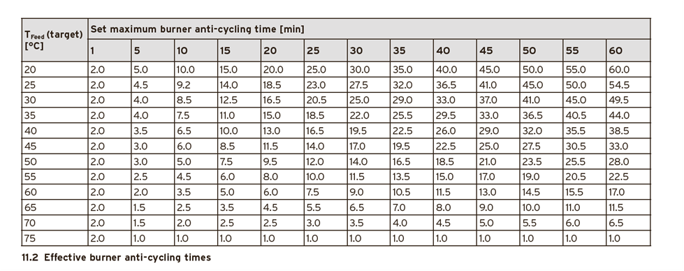
-
Worcester Bosch Greenstar 8000 System Boiler Issues
John Carroll replied to EinTopaz's topic in Boilers & Hot Water Tanks
I suppose so, you can play around with it. It would be interesting to see what the pump modulation goes to and the other data if you remove the minimum clamp. Did the engineer renew anything else apart from the HEX?, you mentioned that he might renew some control card or other??. -
Worcester Bosch Greenstar 8000 System Boiler Issues
John Carroll replied to EinTopaz's topic in Boilers & Hot Water Tanks
Readings boiler / flow target 65 boiler / flow actual 66.5 return actual 52.3 burner output 54% pump output 87% Strange, but the flowrate has hardly changed from with the old HEX flowrate.
-
Worcester Bosch Greenstar 8000 System Boiler Issues
John Carroll replied to EinTopaz's topic in Boilers & Hot Water Tanks
Can you just post a set of readings as is, now. Seems mighty strange that its still firing at 100% = 36kW, return temp will tell alot IMO. -
Worcester Bosch Greenstar 8000 System Boiler Issues
John Carroll replied to EinTopaz's topic in Boilers & Hot Water Tanks
Great news. Amazed though that there was such a difference with the boiler still outputting 13.6kW and apparently over 20LPM flow. You might post a set of readings including boiler modulation/output when steady conditions achieved. -
Worcester Bosch Greenstar 8000 System Boiler Issues
John Carroll replied to EinTopaz's topic in Boilers & Hot Water Tanks
The filling loop can't be the problem even of left open full, it would just lift the boiler relief valve, your flowrate of 21.7LPM while not earthshaking at that high pump head is quite adequate, so suggest wait to see what the engineer comes up with tomorrow, it should be quite interesting. -
Worcester Bosch Greenstar 8000 System Boiler Issues
John Carroll replied to EinTopaz's topic in Boilers & Hot Water Tanks
A conventional by pass mixes HW with the return water and you would be none the wiser except that the boiler had a return temperature display which would then read and be higher than your return measured temperature, it would not affect the flow temperature whereever its measured. -
Worcester Bosch Greenstar 8000 System Boiler Issues
John Carroll replied to EinTopaz's topic in Boilers & Hot Water Tanks
Just thinking thermodynamically............. We know that your measurements of 54C/45C are correct, I would also be quietly confident that my calulated flowrate of 21.7LPM (based on your data) is correct), if we accept that the actual flow temperature leaving the HEX IS say 70C then there is only one thermodynamic explanation for your measured flowtemp of 54C and that is that there is massive bypassing going on internally for one reason or another where some of return water at 45C is mixing with the water at 70C leaving the HEX. By calculation, this means that 21.7LPM return water at 45C is entering the boiler, 13.9LPM (at 45C) is bypassing the HEX, the remaining 7.8LPM at 45C is entering the HEX and leaving at 70C to mix with the bypassing 13.9LPM at 45C to give 21.7LPM at 54C exiting the boiler. (13.9*45)+(7.8*70)=(21.7*54). Far fetched?? I wonder. -
Worcester Bosch Greenstar 8000 System Boiler Issues
John Carroll replied to EinTopaz's topic in Boilers & Hot Water Tanks
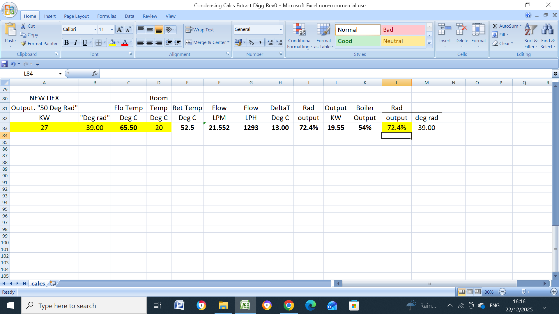
Rad dT is a moveable feast if the flowrate remains constant like it does on quite a lot of boilers. In the above (subject boiler) a 54C flow temprature results in a boiler output of 13.6kW with dT of 9C, if that flow temperature was increased to say 70C either manually or by outside temperature compensation, the boiler output will increase to 22kW but the dT will also increase, to 14.6C, for the same flowrate of 21.7LPM.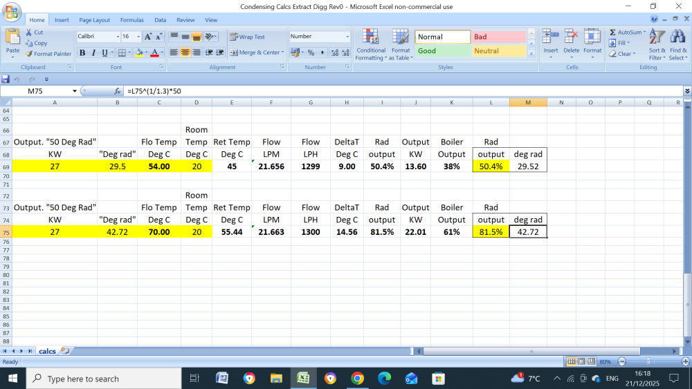
-
Worcester Bosch Greenstar 8000 System Boiler Issues
John Carroll replied to EinTopaz's topic in Boilers & Hot Water Tanks
Of course they will equalise, the $64,000 question is why is there is such a difference in temperature between the alleged flow target temperature and a measurement on the flow pipe a foot or two away from it, hopefully, all will be revealed tomorrow. -
Worcester Bosch Greenstar 8000 System Boiler Issues
John Carroll replied to EinTopaz's topic in Boilers & Hot Water Tanks
One very important bit of data...what was/is the boiler output % with the above 54C/45C?? My calcs show 38%, 13.6kW (based on the above) and a very healthy flowrate of 21.6LPM/1299LPH. 54C/45C/dT9C. 21.6LPM/1299LPH. (See below) On Monday you might ask this senior engineer to monitor the flowtemperature with a independent sensor attached as close to the actual sensor as possible and compare them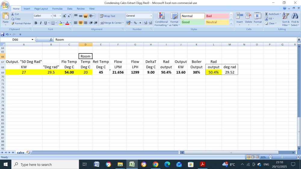
-
Worcester Bosch Greenstar 8000 System Boiler Issues
John Carroll replied to EinTopaz's topic in Boilers & Hot Water Tanks
This boiler doesn't measure the dT because it doesn't have a return temperature sensor, also the pump is (customer) clamped to virtually constant speed. -
Worcester Bosch Greenstar 8000 System Boiler Issues
John Carroll replied to EinTopaz's topic in Boilers & Hot Water Tanks
WB certainly confirmed that the external flow sensor was reading the same as their one and presumably the return, but not sure about this one. I might have missed it but what did or do the external sensors read after a extended boiler run?. if both known, then very easy to calculate the flowrate as the constant boiler output will also be known, 40%??. -
Worcester Bosch Greenstar 8000 System Boiler Issues
John Carroll replied to EinTopaz's topic in Boilers & Hot Water Tanks
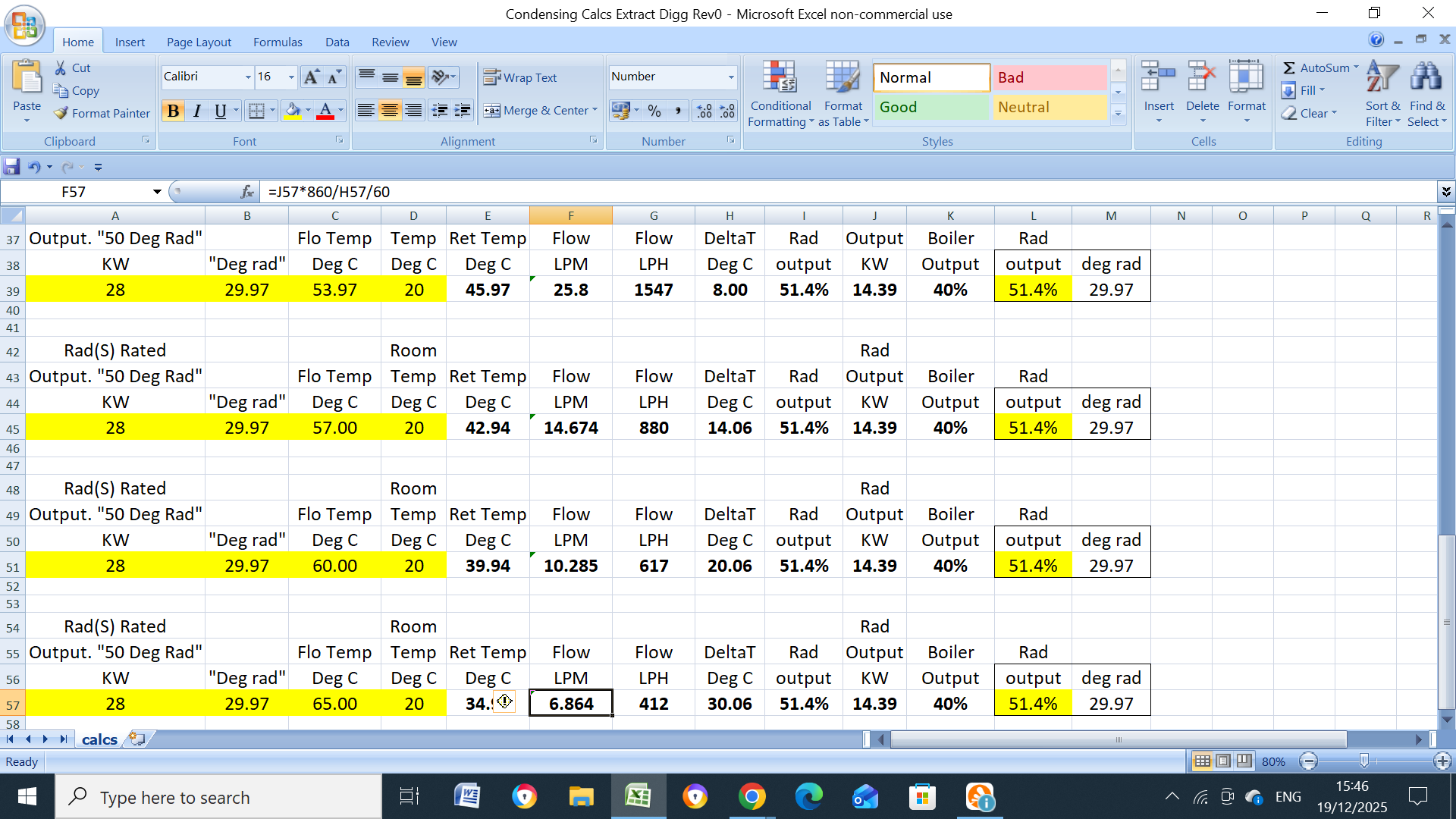
The way I interpret how any boiler controls its output is that it bases it on the target flow temperature ONLY, the flow temperature is obviously influenced by the return temperature which in turn is determined (for a steady heating demand) by the flowrate and the room temperature. You can see below the effect that the flowrate has, the design flowrate of a 36kW boiler is 25.8LPM/1547LPH which I doubt very much that this system is running at. We do know that the steady state output is 14.4kW (40% boiler output) so the numbers below show exactly the flowrates required at different flow temperatures to achieve this 14.4kw (40% output) 54C/46C/dT8C. 25.8LPM/1547LPH 57C/43C/dT14C. 14.67LPM/889LPH 60C/40C dT20C. 10.29LPM/617LPH 65C/35C/dT35C. 6.87LPM/412LPH Its very unlikely IMO that the flowrate is > than 25.8LPM so 54C would seem to be the very minimum flowtemperature required to achieve 40% boiler output, its alos very unlikely that the flowate is as low as 6.9LPM so a 65C flowtemperature is unlikely at this end. I would "guess" that the flowrate is ~ 14.67LPM/889LPH so the steady state flowtemperature is ~ 57C, return,43C, dT14C.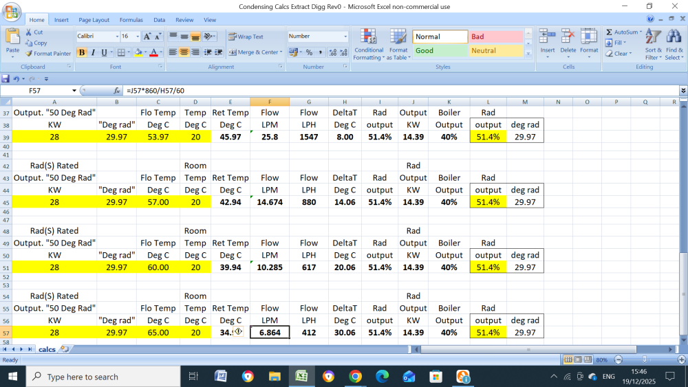
-
Worcester Bosch Greenstar 8000 System Boiler Issues
John Carroll replied to EinTopaz's topic in Boilers & Hot Water Tanks
-
Worcester Bosch Greenstar 8000 System Boiler Issues
John Carroll replied to EinTopaz's topic in Boilers & Hot Water Tanks
What's your next move?. Since WB know that a huge dT exists as measured by their own instruments then they just can't wash their hands of the problem?. -
Would suggest running the pump in CP (constant pressure) mode (second pictogram down) on setting II which at ~ 4.2M head should be ample for your flowrate requirements, suggest setting the flowmeters to 2/2.5LPM, if you have temperature gauges on the manifolds note the readings and compare them with the present readings.
-
Some one asked me some time ago to have a look at this and explain how it works, I got a lot of info from another site and I think this is how it works. It uses time and temperature vs time only in most fairly simple anti fast cycling methods, Vaillant use a table of time+target temp. WB 2.3B Anti Fast Cycle Time, (settable) 3 to 45 minutes, default 5 minutes. 2.3.C Anti Fast Cycle Flow Temperature Hysteresis, (settable) 2C to 15C, default 6C His is set, 12 minutes and 7C. The "anti fast cycle time" is actually the last running time of the burner, if the last running time was 12 minutes or more then the boiler will refire when the flow temperature falls to target temp - 7C, if the boiler then runs for say only 5 minutes before the next burner cut then it will not look at the flow temperature for (12-5), 7 minutes, if the flow temperature has then fallen to target temp - 7C (or more) then the burner will refire. This would seem to indicate that the minimum anti cycle time is the time taken for the flow temperature to fall to the target flow temp - 7C.
-
Worcester Bosch Greenstar 8000 System Boiler Issues
John Carroll replied to EinTopaz's topic in Boilers & Hot Water Tanks
A modulating boiler cannot have the cut out at its target value, otherwise the burner will shut down every time the target value is reached, a non modulating boiler like my oil fired one, does cut out at its target value and has a ~ 8C hysteresis so will cut back in at target value - 8C. Also a modulating boiler will fire flat out (or whatever its range rated to) until the target value is reached, it will then ramp down once the target value is reached or slightly higher so its vital to have 4/5C leeway to avoid the burner tripping needlessely, I often see my daughters Vokera Vision 20S firing up and it exceeds the target value by 2/3C before it ramps down sufficiently to match the load, it will then maintain the target value within + or - a degree or two, as you say also useful when antcycling. I think modulating boilers also don't enable refiring until the measured value is at targer value - 5C or so, obviously, since most gas boilers fire up at ~ 65% output then the anti cycle period is timed so that the measured value is well less than this to avoid excessive overshoot on refiring. -
Worcester Bosch Greenstar 8000 System Boiler Issues
John Carroll replied to EinTopaz's topic in Boilers & Hot Water Tanks
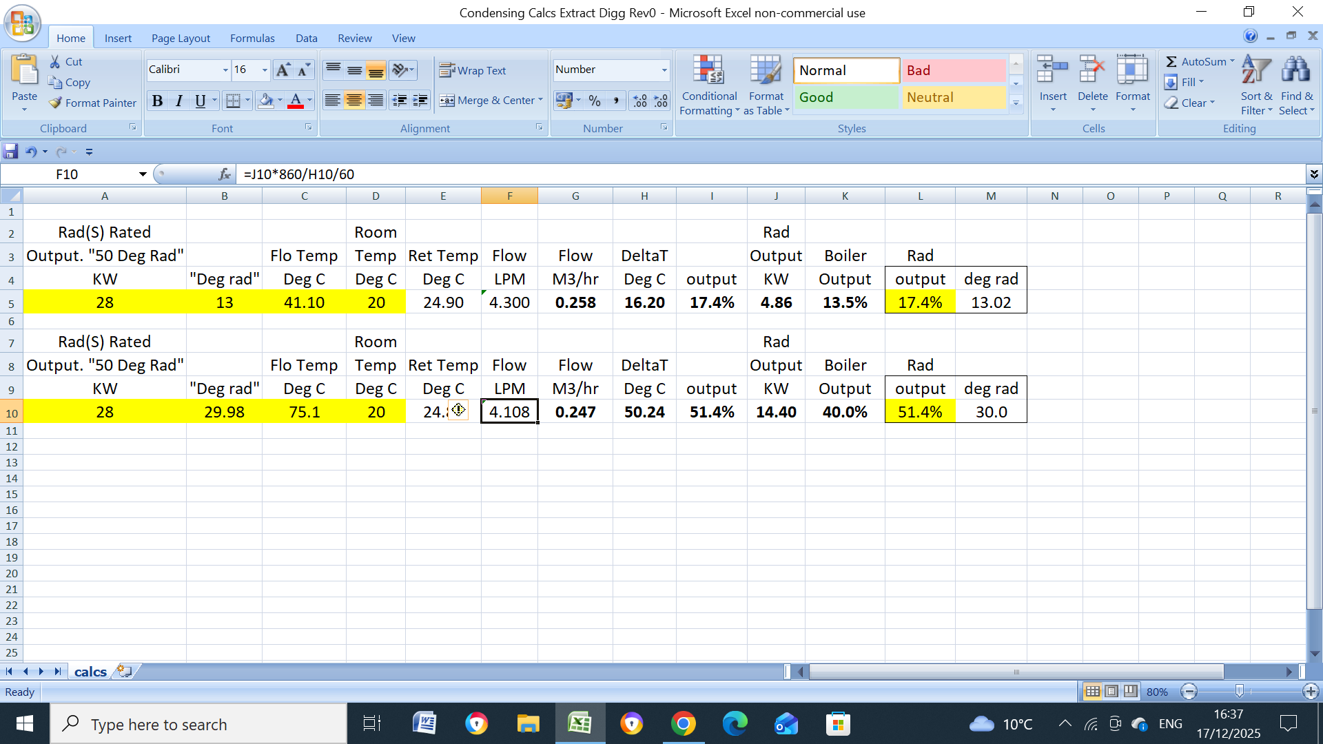
Interesting, if the measured flow&return temperatures are a steady 41.1C/24.7C then the boiler is just about running at its minimum output, by calculation its running at 4.86kW, 13.5% modulation but at a utterly abysmal flowrate of 4.4LPM, on the other hand, if, by some miracle its running with a flowtemp of 75C but with the same return of 24.9C then it's output is 14.4kW, 40% modulation, but at a huge dT of over 50C which most boilers would not continue running with, (max dT normally tolerated is ~ 30C), the WB does not monitor the return temperature.
-
Worcester Bosch Greenstar 8000 System Boiler Issues
John Carroll replied to EinTopaz's topic in Boilers & Hot Water Tanks
Can you recall what the boiler modulation was with your 41.1C/24.7C flow/return temperatures and was it and those two temperatures reasonably steady? If not, have you any numbers (modulation + flow/return temperatures) when it was?. -
Worcester Bosch Greenstar 8000 System Boiler Issues
John Carroll replied to EinTopaz's topic in Boilers & Hot Water Tanks
IMHO, there is only one logical explaination for the huge dT between the target/flow displayed temperature and the measured flow pipe temperature (and confirmed by the attending WB engineer) and that is, the displayed temperature is not tbeing taken from the flow pipe sensor but probably from the boiler HEX. It doesn't matter what kind of throttling or flowrates, as long as the boiler is firing continuously then because there is probably well less than 0.5L of water between where the boiler flow sensor is attached and the manual measuring point which means that even with a flowrate as low as 5LPM should only "take" this vol of water 5 or 6 minutes to reach the manual measuring point once it does then there should be little or no difference since the flowtemperature is then very constant for relatively long periods. -
Insufficient flow rate for Samsung ashp
John Carroll replied to Simon Brooke's topic in Underfloor Heating
A ABV will only work properly IMO when using fixed speed (constant curve) mode where (on a centrifugal pump), the head increases as the flow rate decreases, some suggest that it will work with the pump in CP (constant pressure) mode but then also requires a fixed restriction (a valve?) installed in series with it, I really can't see this working properly. If the ABV is installed as far away from the pump/boiler as possible then this should possibly help as the pipe loss decreases with decreasing flow which means increased head at the ABV and vica versa, the constant pressure is only maintained at the pump. -
Insufficient flow rate for Samsung ashp
John Carroll replied to Simon Brooke's topic in Underfloor Heating
Found this in the attachment but seems strange that this subject unit does not have its own pump?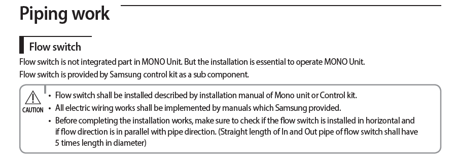
-
Insufficient flow rate for Samsung ashp
John Carroll replied to Simon Brooke's topic in Underfloor Heating
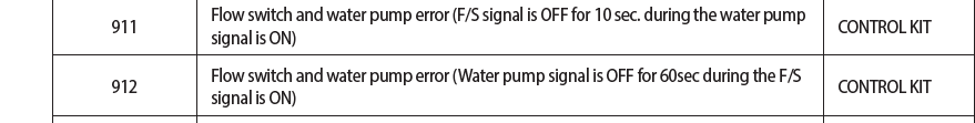
Just wonder if there is a actual interlock via a flowswitch, etc, it just says the unit can stop, page 23, I think they can trip if the flow/return dT is too low, some alarm is surely flagged if the unit refuses to start. Could be something else stopping this unit from starting. There should really be a ABV between the flow&return anyway.