John Carroll
-
Posts
577 -
Joined
-
Last visited
-
Days Won
3
Everything posted by John Carroll
-
UFH Mixing Valve advice on Air Source Heat Pump set up
John Carroll replied to MorganP's topic in Underfloor Heating
The piping diameter will have a huge effect on the pump head required, what is the outside diameter of your loop piping?. -
UFH Mixing Valve advice on Air Source Heat Pump set up
John Carroll replied to MorganP's topic in Underfloor Heating
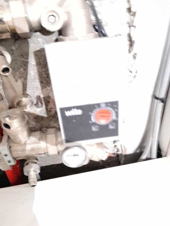
Is that a 6M Pump and has it just 3 settings, what dia loop piping?. -
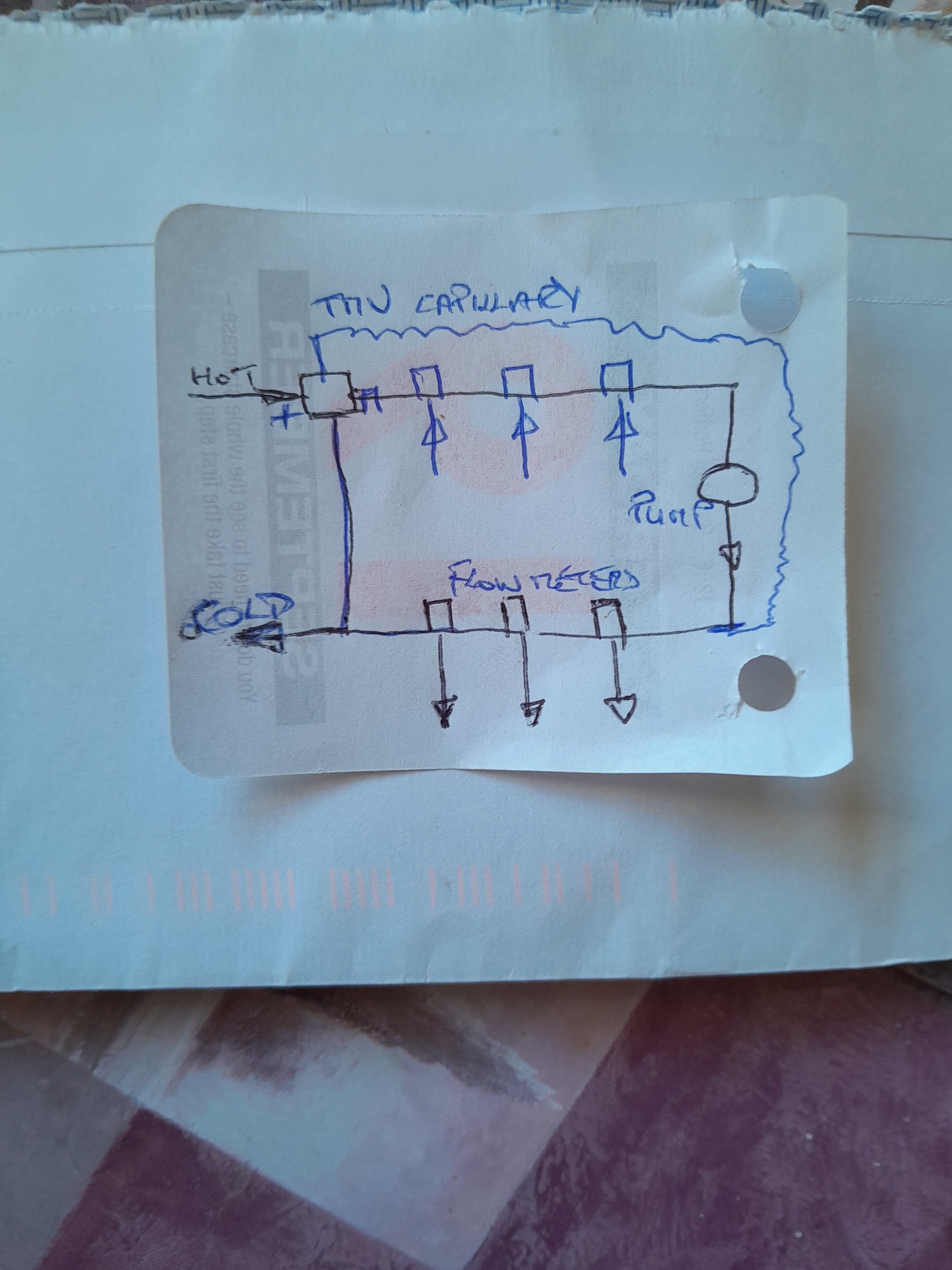
No John, not really, the oil fired boiler here has a TMV to maintain 40C return to prevent corrosion but I've omitted it for simplicity, but I suppose gas fired boilers on UFH only can be run with very low flow/return temps and some can now modulate down to ~ 2.0kW, so some impact here, still it seems a very unconventional way of implementing the UFH and took me a long time to realize that the mixed water can also be used to reduce the UFH flow temperature. I think this schematic might show how this system was running when I noted the data.
-
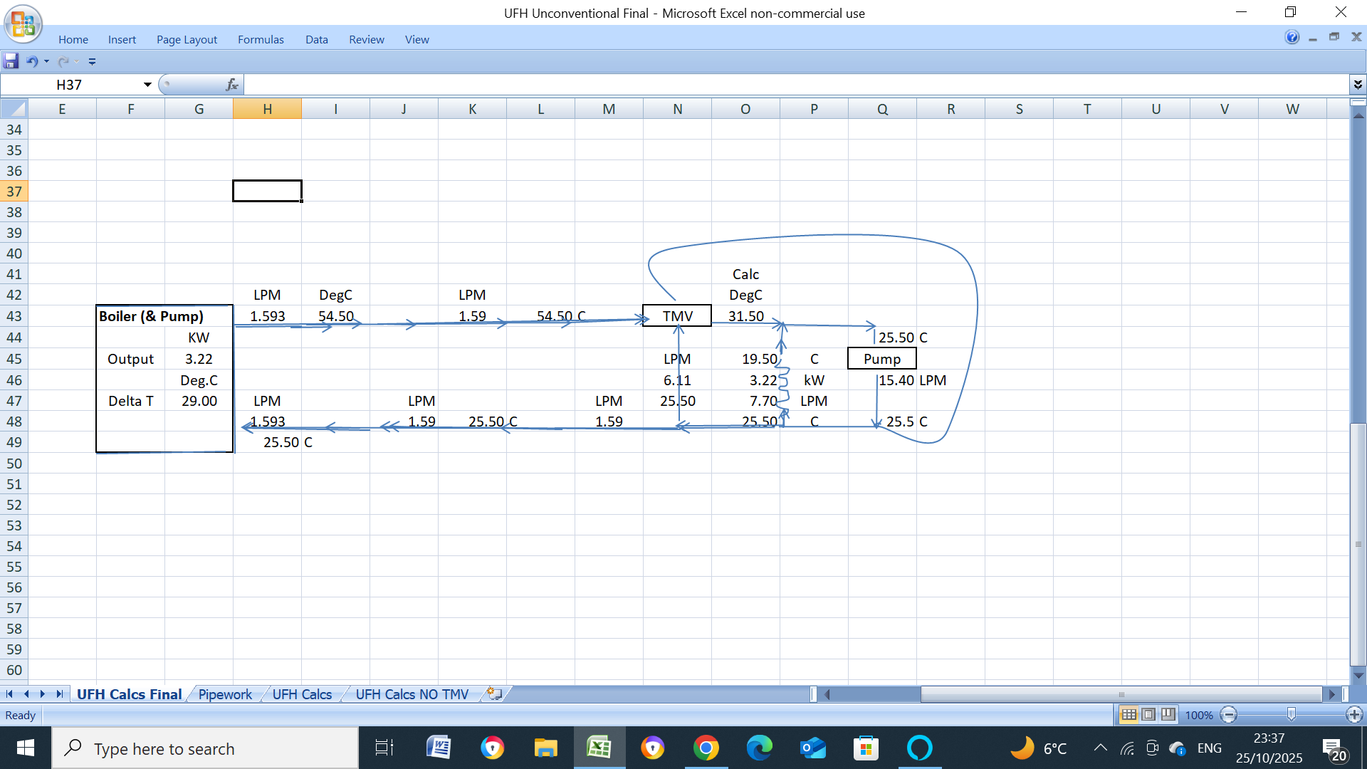
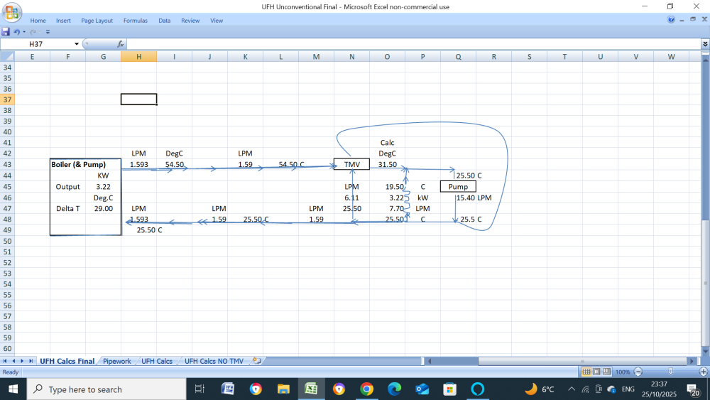
Glad to report that after viewing it, I can see that this UFH is operating fine. The manifold pump is pumping downwards, the 3 flowmeters are reading a total of (2.5+2.7+2.5), 7.7LPM, the UFH loops are operating at a dT of, (25.5-19.5), 6.0C, this gves a calculated Boiler/UFH output of (7.7*60*6.0/860), 3.22kW. The downside of this set up is, one, that the mixed water is returned to the boiler and not the UFH outlet water which means that returned water temperature is higher, in this case, returned at 25.5C and not 19.5C, resulting in a slight loss in condensing efficiency, and, two, the manifold circ pump is circulating at twice the UFH loops flowrate resulting in greater pump power required.
-
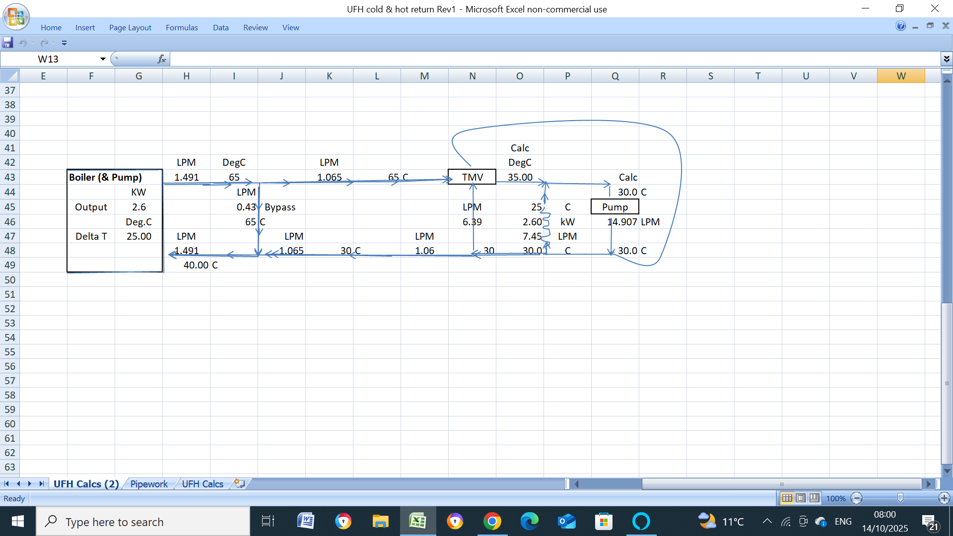
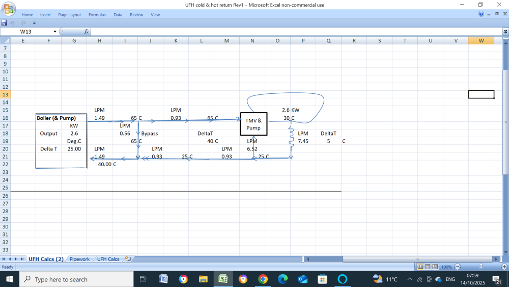
Think we can finally put this to bed now as it must? operate like shown immediately below IMO, only difference is that the boiler return water temperature will be the UFH dT higher than the conventional setup plus the manifold circ pump will be circulating almost double the flow. I will post the actual numbers when I see this UFH system. Conventional System

-
A bit off topic but why are those UPM pumps so popular on UFH manifolds?,
-
Is this normal? Pressure jumps on stop
John Carroll replied to Andeh's topic in Air Source Heat Pumps (ASHP)
No, it shouldn't, as suggested, the pre charge pressure should be checked first but will require a full or partial system drain down, depending on where the EV is installed, then suggest pre/fill pressures of 1.0/1.5bar. -
UFH Mixing Valve advice on Air Source Heat Pump set up
John Carroll replied to MorganP's topic in Underfloor Heating
If its the top of the flow meter(s) is the flowrate then you only appear to be circulating ~ 1.0LPM/loop, 4C seems a very low dT for that very low flowrate. Every 1.0LPM at a dT of 4C will give a output of, 1.0*60*4/860, 0.28kW, 11 loops equals 11*0.28, 3.1kW. -
Someone else just pointed out that the bypass is upwards to the valve which does seem more correct as the TMV is close to the UFH manifold pump, anyway the "mystery" to me is solved as its mixed flow temperature water thats returning to the boiler and not the colder UFH return water.
-
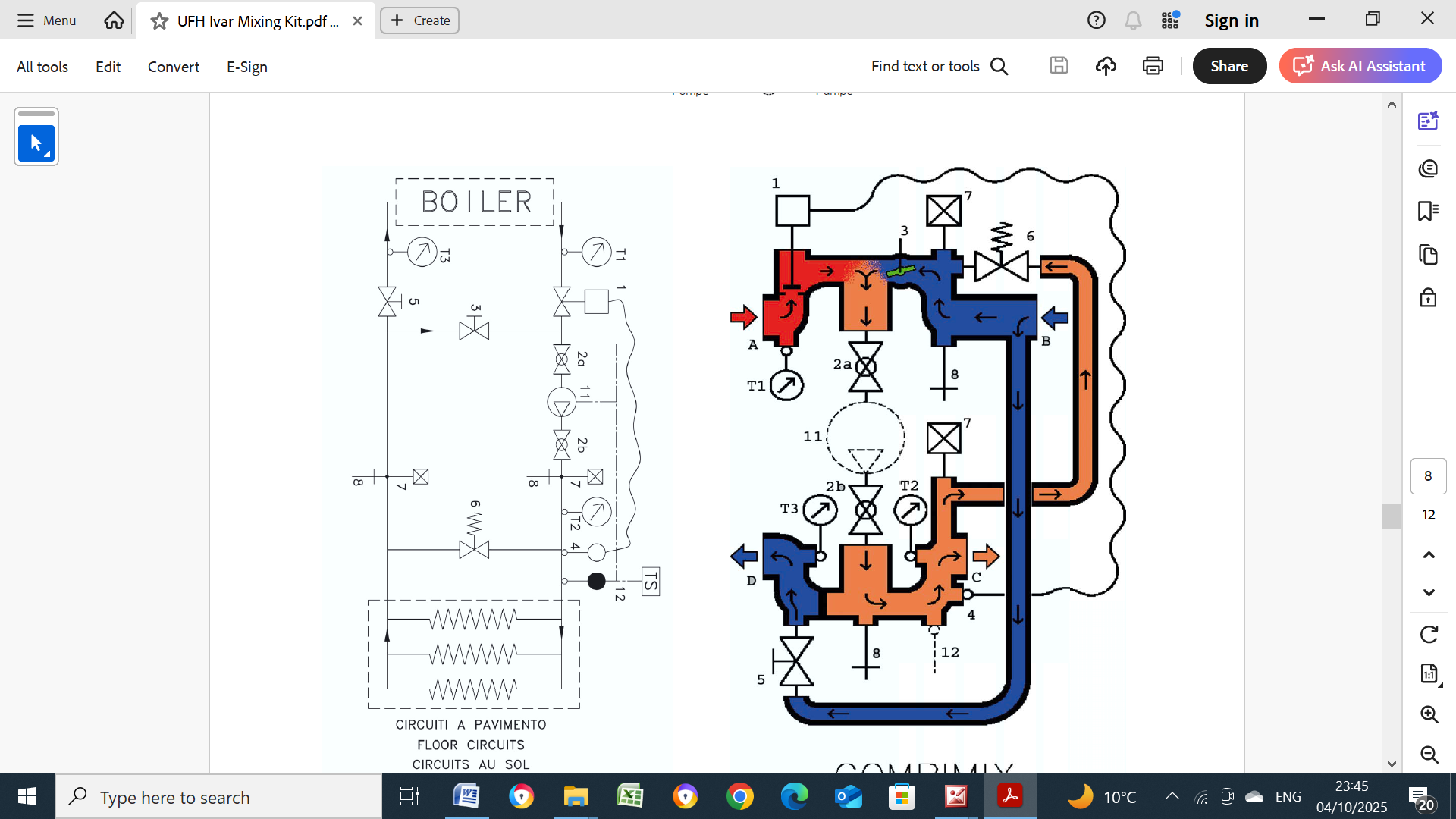
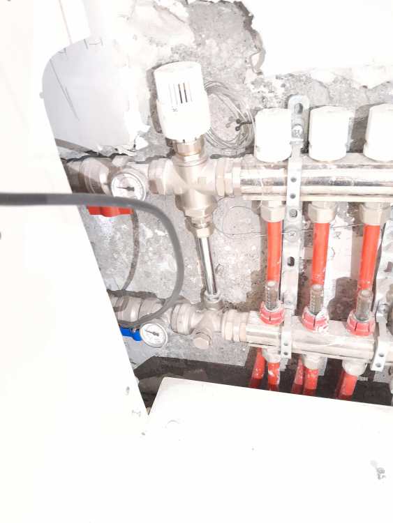
Hopefully, now, 443 viewers can sleep more soundly in their beds tonight, if, as I think the system works this way. It returns the mixed temperature to the boiler, maybe without any 65C hot bypass water or with some hot bypass water if its required to, in the case of a gas boiler, to reduce the dT below 30C and in the case of a condensing oil boiler to avoid low temperature corrosion, some/most oil boiler manufacturers recommend a boiler minimum return of 35C/40C. the TMV, I think is a FM 750 Flow Mix valve, I don't know know if its bypass can be regulated or not, @Nickfromwales or @JohnMo might be familiar with this valve. Ivar Flow Mix.pdf UFH with No TMV Bypass.pdf UFH with TMV Bypass.pdf
-
Unlimited hot water with 4 bathrooms - is it possible?
John Carroll replied to Indy's topic in Boilers & Hot Water Tanks
Assuming you opt for a 400L cylinder, when heated to 60C and assuming you would prudently leave say 50L after showering then 350L at 60C (and assuming a mains temp of 10C) will allow almost 19.5 minutes showering time for 2 at 15LPM @ 40C or almost 13LPM if 3 showering together, the recovery time to 60C assuming a average coil output of 20kW will be just over 60 minutes or with a average coil output of 25kW, 40 minutes. Probably a "step too far" for you, but a 20/25kW output PHEX would still give you unlimited HW after the 350L is used up.... a continuous flow rate of 9.56/11.95LPM at 40C. -
Is this normal? Pressure jumps on stop
John Carroll replied to Andeh's topic in Air Source Heat Pumps (ASHP)
I would remove one end of the filling loop to ensure neither isol valves passing. 150L system contents assuming cold water temp of 10C and hot of 50C + a 18L EV with precharge/filling pressures of 1.0/1.5 will have a hot final pressure of 1.85bar, even if the pre pressure was reduced to 0bar then a filling pressure of 1.5bar will still only result in a final hot pressure of 2.31bar A system contents of 205L will still only result in a final hot pressure of 2.0bar with 1.0bar/1.5bar pre/fill pressures. -
Unlimited hot water with 4 bathrooms - is it possible?
John Carroll replied to Indy's topic in Boilers & Hot Water Tanks
Maybe the OP should decide what is his/family's acceptable showering flowrate is, then decide if he requires 3 x showering simultaneously or, IMO, a more realistic 2, then, that will surely go a long way to determine the cylinder capacity , etc. -
Unlimited hot water with 4 bathrooms - is it possible?
John Carroll replied to Indy's topic in Boilers & Hot Water Tanks
Whatever system you go for, It might be prudent to consider installing a say 10kW electric shower which may not be too popular with the children but will still flow ~ 5LPM, not too far away from the showering experience of 6LPM I am now increasingly getting in Hotels on my frequent trips abroad with their Eco showers, purely in the interest of saving the planet of course. The stand alone shower would also be a good back up if/when the boiler breaks down even if you have heating elements in the cylinder. -
Unlimited hot water with 4 bathrooms - is it possible?
John Carroll replied to Indy's topic in Boilers & Hot Water Tanks
Thats quite interesting when you think about it, but it depends on where the coil is positioned in the cylinder, see below. My own 150L vented cylinder has 3 very tightly wound microbore solar coils connected in parallel but only take up about 23L ("height") in the bottom of the cylinder, from 11L to 33L from the cyl bottom the 0,65m2 coil has a total "height" of 55L, the bottom coil connection is 44L from the cyl bottom and the top coil connection is 99L from the cyl bottom, there is also a top mounted electric immersion element that heats ~ 28L, three PT1000 probes, 38L, 73L & 123l from the cyl bottom, I've obviously often observed three different cyl temperatures but its almost uncanny how stratification works, if say the bottom solar probe is 20C, the middle probe is 40C and the top probe is 60C when the sun comes up, coil& immersion both off, then the bottom solar probe will start rising but the middle probe will stay exactly at 40C (& the top probe at 60C) until the bottom probe reaches 40C, then the middle&bottom probes will both start rising exactly together until thety both reach 60C, then the middle, bottom & top probes will rise at exactly the same temperature (to within 1C) until the whole cylinder reaches ~ 80C, I have a TMV on the HW outlet. So, back to reality, if say, the whole cylinder is at 55C and the boiler cuts in to heat the 106L then no matter how cold the coil might be initially, there will still be almost 50L of water available at exactly 55C, by which time, even if having a shower which with a oil or gas fired boiler is literally a few minutes the coil will be up to its normal temperature and the bottom 100L will probably only have cooled by ~ 5C or so to 50C, no big deal?. Mixergy, with their PHEX have I think two different secondary return stratigies, with gas firing with very high flow temperatures they return is at the top of the cylinder and thats why I suggest it might be worth looking at this for a "endless" HW supply because even if the cylinder is totally exhausted, a say, 25kW system boiler will still give a DHW flowrate via the PHEX of 11.95LPM (continuously like a combi) at 40C from a cold mains of 10C. Using a ASHP then to keep a reasonable COP the cylinder heating has to have a much lower dT while reheating so the return is back into the bottom of the cylinder, heating from bottom up. My HW Cylinder.pdf -
Solar Thermodynamic - anyone using?
John Carroll replied to BotusBuild's topic in Solar Thermal (ST)
I think these (thermodynamic) had/have a small solar panel combined with a HP, I did see a few about but the problem with them is that the solar panel, in effect, the evaporater, can freeze up leading to very poor COPs. Ariston and others make fully fledged ASHP stand alone units for cylinder heating, I knew someone that has a Ariston Nuos? for a good few years and was very happy with it. These are the type/make I've seen around. https://www.lvprenewables.ie/thermodynamic-solar-panels/?gad_source=1&gad_campaignid=190000387&gbraid=0AAAAAD2YT0cjqg7iVPQZdpMCzZks0klRH&gclid=Cj0KCQjwrojHBhDdARIsAJdEJ_dP-3EBFueQJGiDtwoDgBYE5xEFuoXluMm0ecVn5rf27D4UNnhKMekaAvvZEALw_wcB -
I appreciate all answers John, the nearest arrangement I can find is the one below which makes perfect sense.

-
Apologies to all, thought I was on another web site!.
-
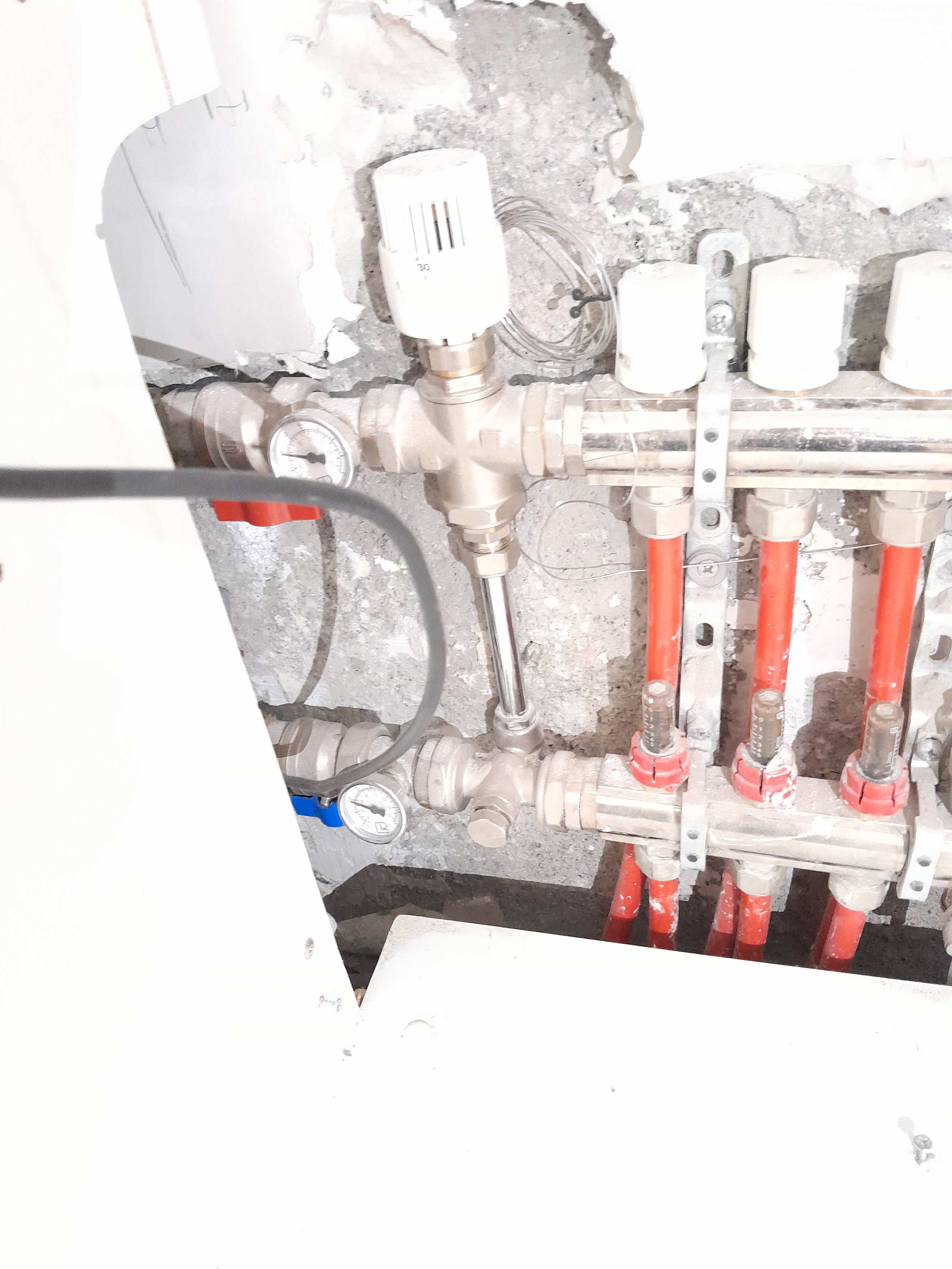
This setup is apparently working fine for the past 10 years, its set to give a UFH temp of 30C from a oil fired boiler running with a 65C flow temp. I havn't seen it in action yet but just can't figure out how it actually works, the manifold pump is pumping downwards but I can't see how any cold (UFH manifold return) water is returned to the boiler.

-
Grundfos Pump Occasionally Stalls on Willis based UFH system.
John Carroll replied to TerryE's topic in Underfloor Heating
The UPS2 should require ~ 23W at the above flowrates on minimum fixed speed, 4M head.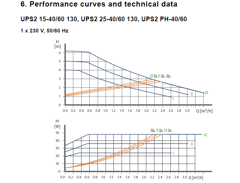
-
Grundfos Pump Occasionally Stalls on Willis based UFH system.
John Carroll replied to TerryE's topic in Underfloor Heating
Something not adding up there Terry assuming you have a A rated pump. You say you have 3 x 95M loops, assuming 16mm pipe, 12mmID, and assuming a flowrate of 2.5LPM/loop then the friction loss is ~ 1.7M/loop, add 15% for bends etc gives ~ 2.0M loss, 3 loops X 2.5LPM = 7.5LPM, 0.45m3/hr, so the pump must deliver 0.45m3/hr at a 2M head. If your pump curves look like the ones below then the power required should only be around 12W yet your pump is pulling ~ 40W, pump may be on the way out or else, for some reason or other its running with over a 6M head to draw 40W at ~ 0.45m3/hr.
-
Unlimited hot water with 4 bathrooms - is it possible?
John Carroll replied to Indy's topic in Boilers & Hot Water Tanks
A 37kW combi will give a flowrate of 15.2LPM at @dT of 35C, you said in your first post that the pressure was a bit low, by which I take it you mean flowrate, this may have nothing to do with the boiler output but the actual flowrate itself is too low, in which case the boiler will just modulate down in output to match the demand. If two could shower at the same time at a flowrate of 7.6LPM each, would this be acceptable? the Navien will give 11.0LPM each if 2 showers in service and theoretically 7.3LPM if 3 showers in service, practically speaking I would think its unrealistic to expect 3 showers in service together so maybe go for a well known boiler make of ~ 40/50kW rather than the Navien which might only have a limited pool of experienced installers for servicing etc. -
Unlimited hot water with 4 bathrooms - is it possible?
John Carroll replied to Indy's topic in Boilers & Hot Water Tanks
The 54kW Navien, will give a flowrate of just over 22LPM at @dT of 35C, in other words a showering temperature of 40C from a winter very cold mains of 5C, or 42C from 7C, so will supply 2 showers at a flowrate of 11LPM, acceptable? or 7.3LPM if 3 showers in service. What is the existing make/model/output of your existing Combi? -
Unlimited hot water with 4 bathrooms - is it possible?
John Carroll replied to Indy's topic in Boilers & Hot Water Tanks
I think @Indy has lost interest anyway. -
Unlimited hot water with 4 bathrooms - is it possible?
John Carroll replied to Indy's topic in Boilers & Hot Water Tanks
Surprised to hear that, here, oil fired boilers are banned from 2022 and gas fired boilers from 2025, in new builds.