sharpener
-
Posts
1492 -
Joined
-
Last visited
-
Days Won
1
Everything posted by sharpener
-
Just happened across this thread. Traditionally the kitchen cold supply was the only thing that came directly off the rising main to the tank in the loft, other outlets in the house would come from the (unwholesome) tank. When did this all change to requiring a balanced supply per G3? I suppose this is to ensure the same pressures at a kitchen mixer. If you don't have a mixer (like my separate pillar taps!) does it matter?
-
I was wrong, the Forge Steel is the one they stock https://www.screwfix.com/p/forge-steel-adjustable-basin-wrench-1-2-3-4-/410yc, looks about the same size. Now in my hand, it seems robust enough for occasional use. Agreed Monument are long lasting tools, I have a 30 yr old favourite pipe cutter - but now mostly use a pipeslice. No bc after I have reassembled it with a dab of Molyslip it will be easier to service in the future, as opposed to another new one which is bar tight.
-
OH is going to pick up the Faithfull equivalent from Screwfix for £9-99 on way to weekly shop. Have got cap off now but the head is so tight in the body I can't shift it with a 12" Bahco wrench without threatening to undo the union below (putting kitchen tap and dishwasher out of use), tap will have to come out so I can put body in a soft-jawed vice. No longer a 10 minute job (are they ever?), at least then I can put it back with the correct brass backnut and fibre washer.
-
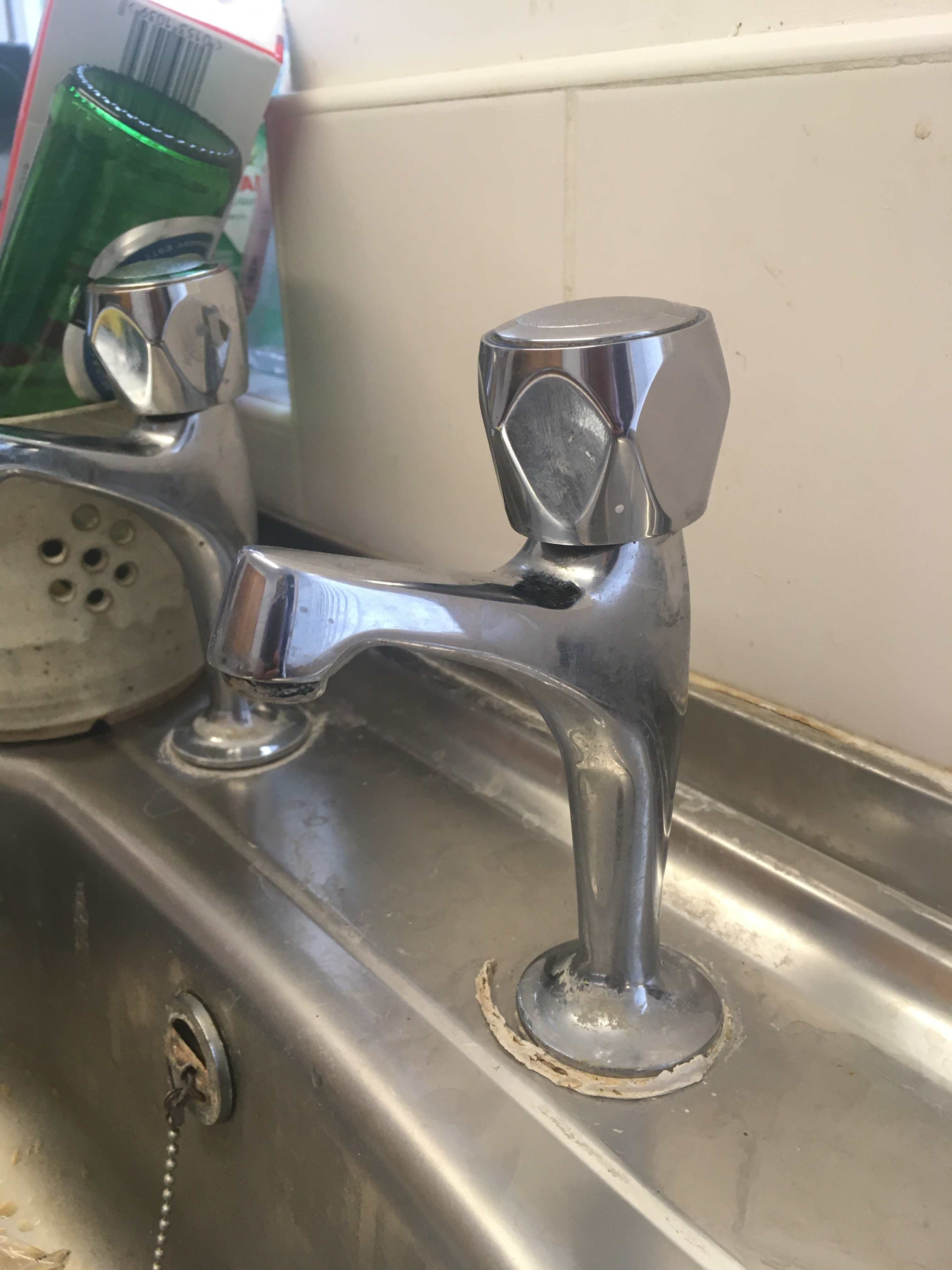
Thanks. To elaborate am I trying to just get the central chrome bit out leaving the blue plastic ring behind? I have tried a thin knife blade, perhaps I just need to push harder but I would OH would like to avoid cosmetic damage. The action doesn't feel like a cartridge, more like an old-fashioned washer. In any event it goes round multiple turns. Unfortunately I can't easily change it. The plastic backnut split in two as stupidly I had not swapped it for a brass one so there is now a lash-up holding the tap down hence the broken packing round the base. The whole sink cupboard unit was pre-assembled and then fitted in its final position and a tiled splashback installed above. I don't think there is clearance to change the tap without reversing some of this.
-
... bought from B&Q maybe 10 years ago? Needs a lot of turning to turn off completely so I would like to try rewashering it. No visible grub screw. Can't prize any cap off the top to get at any fixings. Can't turn it on far enough to see any hex flat underneath to unscrew the headworks. Any ideas?

-
ASHP outdoor unit heating pump Q
sharpener replied to BotusBuild's topic in Air Source Heat Pumps (ASHP)
This may help https://johncantor.uk/pressure+flow/simulator.html -
Vaillant ashp (my battle with).
sharpener replied to zoothorn's topic in Air Source Heat Pumps (ASHP)
Nothing to do with radiators. The AGA consumes oil at a rate IIRC of 6 or 7 kW, and maybe half of this is lost through the cladding to heat the kitchen directly. A small amount of heat goes through the uninsulated ceiling to the master bedroom directly above, and the flue contributes a bit more as it goes in a duct up through the bedroom from which the air is extracted by the MVHR to keep the false wall free of the penetrating damp in the W-facing gable end. The diner half of the room has UFH of unknown spacing which gets the slate floor just perceptibly warm. All the rads are in the rest of the house. -
Vaillant ashp (my battle with).
sharpener replied to zoothorn's topic in Air Source Heat Pumps (ASHP)
You have still misunderstood. AFAICS with the VRC 700 you cannot have 3 different temps (though you can with the 720). See the pic from the manual I posted upthread. I have a barn conversion with thick stone uninsulated walls like yours. It is bigger than we need (except when we have guests) so we don't try and heat all of it all the time. The kitchen diner is heated by the AGA. The bedroom is heated first thing and last thing by the two rads, but the walls stay cold. The living room is heated by the two rads only from lunchtime until we go to bed. This is not conventional but works for us so I suggest you try it. -
Vaillant ashp (my battle with).
sharpener replied to zoothorn's topic in Air Source Heat Pumps (ASHP)
I am concerned about references to flow temperature in recent posts. Normally you do not control this directly, the flow temp for radiators is set by the controller according to the Outside Air Temp - colder outside means hotter water - according to a Heating Curve which is a whole new topic in itself. Start by reading Mick Wall's excellent tutorials here https://energy-stats.uk/vaillant-arotherm-basic-settings. Meantime do not tamper or change this aspect as other things need to be sorted first. [There are situations where you do not want the Heating Curve to apply e.g. towel rails but that is a specialist area.] No. Zones are separate geographical areas of the house. You may or may not have more than one (I suspect not). What you are describing is a Setback period. There is no distinction between night and setback periods. You can have up to 3 Daytime temp periods in 24 hours, everything else is Setback. This can be either a defined temp (in Setback mode) or heat pump OFF (frost protection only - Eco mode). As it says in the manual: 5.2.3 Setting time programmes You can use the Time programmes function to set the time periods. If you have not set any time periods, the controller uses the time periods set in the factory settings.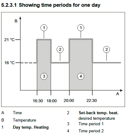
-
Vaillant ashp (my battle with).
sharpener replied to zoothorn's topic in Air Source Heat Pumps (ASHP)
I was thinking of the S20/S21 contacts in the outdoor unit which I use to shut the HP off if the mains supply fails, as otherwise it would discharge the battery far too fast and there would be nothing left for lights and TV. But there are also the EVU terminals in the indoor VWZ AI interface box which are designed for the electricity utility to shut the HP down as a load shedding measure. Assuming this is in a suitable place you could use it with a 3rd-party time switch or even an ordinary light switch to give a simple on/off facility. -
Vaillant ashp (my battle with).
sharpener replied to zoothorn's topic in Air Source Heat Pumps (ASHP)
OK, here is the instruction manual for your VRC700 https://elearning.vaillant.com/vrc700/ci/en/documents/uk/infopool/Operating_instructions.pdf The timer mode on this controller is called AUTO. Setting up the mode and time schedule is explained on p13 et seq. Note that there are two sub-modes. The factory default setting is ECO. This will turn the HP completely OFF overnight which is what you say you want.Though I have some misgivings about that, the alternative is SETBACK where you have control over the overnight temp. I wonder if moving it to the landing would be an acceptable compromise, at least it would be in a circulation space not shut away. You can do this with a Vaillant but you can't connect into the ebus, you need to wire it directly into terminals in the outdoor unit which is not really a DIY job. -
Vaillant ashp (my battle with).
sharpener replied to zoothorn's topic in Air Source Heat Pumps (ASHP)
Good luck with that. V will argue that the VRC700 is compatible and they did not agree to upgrade the control box. To understand whether this is a relevant factor we need more detail of the HW "glitch". Of course. Better for @zoothorn to get to know the underlying physics, how his system works, its capabilities and limitations. But in the real world he may have to shell out folding money instead. -
Vaillant ashp (my battle with).
sharpener replied to zoothorn's topic in Air Source Heat Pumps (ASHP)
AIUI the (white) VRC700 is compatible with current production HP units and probably capable of everything you need. So I would not count on a VRC720 upgrade being the fix to whatever is wrong with your HW (which you do not describe in detail), though it is perfectly feasible to DIY involving only low voltage wiring as it does. Also if you are going to upgrade then worth considering a switch to the wireless version while you are at it to get the internal temp sensor in a more sensible place. However this as already noted will involve fitting a wireless receiver and a new OAT sensor as well. This will be a considerable extra cost and you might struggle to recommission the new setup without paying for professional help. Then I would also recommend getting the internet interface installed so you can control the whole system from your smart phone which for everyday things is much easier to do. Unfortunately finding someone to do all this might not be easy, from the Vaillant FB forum it seems installers do not like working on systems they did not originally install as there is so much scope for things to go wrong. So in summary my recommendation would be to get the current setup working properly first. Have you looked at the Heat Geek map to see if there is someone on their register near you? They seem to be quite highly regarded though I have no personal experience. -
Vaillant ashp (my battle with).
sharpener replied to zoothorn's topic in Air Source Heat Pumps (ASHP)
The Vaillant FB forum is quite useful as well https://www.facebook.com/groups/488794632317506/?sorting_setting=RECENT_ACTIVITY. I see where my confusion about the 240 came from, the engineer is correct, it is present in the VWZ AI interface unit. The mode you want is defo called Time-controlled on the VR720. I think it is similar on the VR700, the differences are mainly cosmetic. It is only when you select Time-controlled that the Weekly Schedule option appears in the menu, this is where you set up the setback times as per @Nickfromwales' last post. Moving the VRC700 is a feasible DIY job but I would make sure you are happy setting up the schedule first. -
I have got one in a garage separate from the main house and one in an outside loo, both 3kW Triton. They are fine for hand washing, and the occasional sink full for cleaning bigger things if you are prepared to wait. There is a diaphragm which I have had to replace because it no longer sealed properly, the replacement was ~£30 IIRC which I thought outrageous for what it was but at least was available. If you wanted a hot supply e.g. for regular washing up then the 7kW is the minimum viable size IMO but still not an adequate replacement for a proper hot supply from a cylinder.
-
Vaillant ashp (my battle with).
sharpener replied to zoothorn's topic in Air Source Heat Pumps (ASHP)
ON is actually called Manual, see upthread. When you are trying to set up the setback schedule the controller mode has to be set to Normal. If it is set to Eco the HP will be off during the setback periods. Yes it is complicated, the phone app is better but there are things you can't adjust with it and this is one of them. To make things worse there are two other things called Eco, one is the power level used to heat the hot water cylinder, I can't remember the other... -
Vaillant ashp (my battle with).
sharpener replied to zoothorn's topic in Air Source Heat Pumps (ASHP)
The three fundamental modes on a Vaillant are OFF Time Control (with programmable Schedule) Manual (always ON) If you are to have Setback i.e. a different temp at certain times you have to programme the times, which is why Setback is only meaningful if you are in Time Control mode. This mode allows you to program different temps with a time resolution of 10 mins. You can wire a simple switch across two terminals in the outdoor unit. Or a "normal" central heating controller. This might suit you. As noted above the interface with the phone app is better. The "engineer" does not seem to know much about these systems. In particular the statement that the controller has/needs a 240V supply is not correct. It is supplied at low voltage by the two-wire ebus connection, this does not have to be taken from anywhere in particular so you can connect the controller to the VWZ AI Appliance Interface (white controller), the outdoor unit, or anywhere along the cable connecting the two. It is the internet interface box that needs a 240V supply. -
Vaillant ashp (my battle with).
sharpener replied to zoothorn's topic in Air Source Heat Pumps (ASHP)
Unfortunately @zoothorn has a Vaillant HP so it is not so simple. But it can be done. For most practical purposes the installation has to have at least one VR720 Sensocomfort controller. These come wired or wireless. The outside air temp sensor has to be the same type, so if you are swapping the one you have to swap the other as well. The wireless OAT sensors are not as reliable. IIRC you can add extra wireless thermostats, which are cheaper, but only if the Sensocomfort is already wireless. You would still need to change that so it wouldn't help. So a toss-up, as swapping all the hardware probably not much different from paying someone to move the wired controller. There is no practical limit on distance as the ebus only requires plain twinflex. You can make a Vaillant system work with an ordinary central heating timer wired directly to the outdoor unit, but as you still need a Sensocomfort to set up most of the zone parameters, I wouldn't recommend going down this route. On the whole I would suggest enabling the HP 24/7, with bedroom rads switched off at night with their lockshield valves or smart TRVs and the rest of the house on a chunky 5 deg setback. -
Vaillant ashp (my battle with).
sharpener replied to zoothorn's topic in Air Source Heat Pumps (ASHP)
Having newly returned to this thread it strikes me there is a fundamental misunderstanding of what is meant by ON. Perhaps the term should be replaced by the word ENABLED. In other words the HP is capable of giving heat bc the outside air temp is lower than the high limit, the time is within the scheduled operating times etc. Whether it actually does so is then a function of the measured temperature(s). If control is via a simple thermostat in a sensible place then the HP will provide heated water to the radiators whenever the temp at the thermostat position falls below the set point. Whether the radiators in turn make use of said heated water depends on their TRVs (if fitted). Consequently it is possible for the HP to be running but no heat being supplied to the bedroom. We run ours like this using the pre-existing electronic timer-TRVs bc we want the air in the bedroom to be heated before we go to bed and before we get up but not at other times - the stone walls stay cold, as they did with the oil-fired boiler. I would guess this solution might suit the OP quite well. If there is a more sophisticated overall strategy e.g. Weather Compensation (I don't know if the OP has this) then the temp of the heated water that the HP supplies will depend on the outside air temp (and maybe the internal temp, maybe not). Weather comp will almost certainly require the HP to be ON in the sense of ENABLED 24/7 though many users apply a setback of 1 or 2 deg at night. More than this makes recovery to the daytime temp setting both slow and costly. In practice we do not do this, the living room is a large space but is only occupied about 6 hours a day in the afternoon and evening so this too has rads controlled by the legacy electronic timer-TRVs. This is quite effective and although at odds with conventional thinking again might be more in line with the OP's philosophy. Provided you are prepared to spend £10/day in cold weather. In a big cold stone house that is what it costs whatever approach you adopt. -
ASHP BUS Grant - when does it pay out?
sharpener replied to Great_scot_selfbuild's topic in Air Source Heat Pumps (ASHP)
We had two acceptable quotes, both were on a net of grant basis. I would be very wary of paying more than the net price at any point, they seem to be able to access the BUS grant money in a simple and timely fashion. -
Why did you choose an air source heat pump?
sharpener replied to SimonD's topic in Air Source Heat Pumps (ASHP)
190 sq m barn conversion dating from 1995. Kidde oil boiler not too difficult to keep running but last remaining service engineer (and source of spares) nearing retirement. No gas available. Oil-fired AGA which we have kept. Had already put in 8kW of solar, EV charging point and Victron/Pylontech ESS so HP the obvious next step. Had some difficulty finding an installer who would not insist on replacing the hard-to-get-at hw tank at great expense. Solved with custom 12kW design from Vaillant with thermal store and two heating zones. Eventually got 6 quotes of which 2 were realistic. Job finally done by Eljay in Ivybridge to a high standard, happy with result. -
Bread knife.
-
ASHP low pressure help pls
sharpener replied to canalsiderenovation's topic in Air Source Heat Pumps (ASHP)
Those inline filters get blocked quite easily. In slow time it would be better to bin it and get a Magnaclean or Adey HP filter fitted indoors, they have a much bigger element like an enormous kettle fur collector and a magnet for collecting magnetite particles shed by the radiators - which you should not be gettting if there is adequate inhibitor in the system. Gledhill cylinders have a bit of a reputation for noisy internals, I have seen it reported as a specific quality control issue in the factory. -
ASHP low pressure help pls
sharpener replied to canalsiderenovation's topic in Air Source Heat Pumps (ASHP)
As installed mine had a compliant 22mm D2 setup taken into a first floor soil stack via a Hep2O bladderless trap. Thinking this was where the restriction was I modified it so there was first a 2.5m drop to the ground floor and the trap went into the stack at that level instead. But it is not much better and will still not take the full flow from the tprv. So I think that the whole concept that the pipe below the tundish needs to be only 22mm - one size up - is flawed, the regulations do not achieve their aim and are pointless. And a tundish hidden away in an airing cupboard slowly filling with water is NFG either. Personally I think it would be better to have the relief valve piped in 15mm directly to waste with an electrical or mechanical alarm to indicate there is something wrong and possibly a small air admittance valve to vent the pipe but prevent smells. As a further twist the MCS surveillance visit on another house meant the HP installer was called back to move the tundish to somewhere slightly more visible (even though it was pre-existing and not part of his work). The D2 pipe is 28mm bc of the run length but has a 28mm tundish that will overflow too. So the modification is purely cosmetic, the tundish is still in an alcove off a loft above our bathroom, access is still via a ladder and a door which is kept shut so we will neither see or hear any overflow condition. Which is why I test the tprv whenever I am up there, at least I know it is not stuck and the valve seating is washed clean. -
ASHP low pressure help pls
sharpener replied to canalsiderenovation's topic in Air Source Heat Pumps (ASHP)
But they are ineffective. My installers met all the requirements on paper but the regulation tundish is too small to contain all the splashing. But more seriously, at full flow from the tprv the water backs up in the D2 pipe and would overflow the tundish if I continued the test.