


sharpener
-
Posts
1487 -
Joined
-
Last visited
-
Days Won
1
Everything posted by sharpener
-
Is this normal? Pressure jumps on stop
sharpener replied to Andeh's topic in Air Source Heat Pumps (ASHP)
The ppl who put in my 12kW HP changed the pv from 18 to 25 l, but then I now have 11 upgraded rads on top of ~75 sq m of ufh. Original pv was installed 1996 but is still in good working order so I have saved it with a view to installing it somewhere else entirely. There are online calculators for ufh pipework which it would be worth seeking out to see what the recommended pv size is for your pipework volume. By my very approx calcs you have 230/0.15 = 1500 m of pipe at 0.1 l/m so 150 l system vol + hw coil, HP and primaries etc so 18 litres doesn't sound out of line. -
Is this normal? Pressure jumps on stop
sharpener replied to Andeh's topic in Air Source Heat Pumps (ASHP)
Yes. And if he does not know how to check/adjust the pressure in the current one (see upthread) he won't know how to commission the new one so £150 down the drain and no improvement. Going back to the original post I think there is perhaps a pressure spike when the system shuts down, that's quite likely depending on where the p.v. is in relation to the pump, but correctly set up it should absorb it without difficulty. -
What to expect from an MCS follow-up visit?
sharpener replied to sharpener's topic in Air Source Heat Pumps (ASHP)
Seems not. I have offered to send them pix as a cheaper alternative to fitting a new one! I cannot be absolutely certain the tundish is within the required 500 mm from the valve but it cannot be much more. Why they did not run their hands down the pipe from the relief valve until they encountered the tundish I cannot fathom. Or why the MD did not check the existing cyl for G3 compliance when he did the HP survey. Or ask his plumber who fitted the recirculation pump to the cyl. whether he had checked. At the extreme they might not be happy about the discharge <1m from a public road but it is set back and on a stretch where there is no footpath. Should have written D2! -
What to expect from an MCS follow-up visit?
sharpener replied to sharpener's topic in Air Source Heat Pumps (ASHP)
A surprising development today, had an email to say they couldn't find the tundish and so wanted to come and fit a new one. Here is part of my reply: <The tundish is clearly visible on the lhs of the cyl as you look at it - and you can hear where it is if you release the relief valve. The D3 connection in 22mm copper pipe then goes downwards and out through the North (roadside) wall of the house... AFAIK this is all fully G3 compliant...> -
EVU is the standard way of controlling the HP from a third-party device when the HP system itself doesn't have multiple zones (for these you need a VR70 or 71 Wiring Centre with its own call for heat inputs). However many ppl here and on the Vaillant Arotherm + FB group would say you will achieve a higher CoP by using the room stats only to set an upper limit (try 25C to start with) and only bring them into play if particular rooms are still too hot after you have optimised the weather compensation. Neither, the Vaillant-approved schematic for yr setup has the volt-free contact from the UFH going to the EVU input but the pump should be run off the MA1 terminal on the VWZ AI and controlled by the HP directly. Schematics here https://www.facebook.com/groups/488794632317506/permalink/1072492593947704/, I think you need the one on p6. There is also a recent discussion on the use of MA1 on the same FB group. ETA also with a buffer you need basic System Diagram code 10 not 8 in the setup menu.
- 22 replies
-
- 2
-

-
- solid state relay
- ssr
- (and 1 more)
-
Is this normal? Pressure jumps on stop
sharpener replied to Andeh's topic in Air Source Heat Pumps (ASHP)
I would suspect the EV pressurisation level, my installers left it at the factory setting of 3 bar, far too high. If it is too high or too low it will not be serving any useful purpose - and so appear to be too small. You cannot check it while the system is working, you need first to release the pressure in the primary circuit completely when it is all cold. Then adjust the pressure at the Schrader valve to be just below your chosen system pressure, say 1.2 bar, before re-pressurising the circuit to 1.5 bar or whatever. This ensures the bladder will be slightly compressed by default but capable of accomodating 80% of its nameplate volume in expansion and/or pressure surges. -
Arent't they normally different diameters as the liquid refrigerant is much denser than the vapour returning to the compressor? Don't know for sure as I haven't got one.
-
What to expect from an MCS follow-up visit?
sharpener replied to sharpener's topic in Air Source Heat Pumps (ASHP)
Sounds like your visit was a lot more useful than mine. I had a hospital appointment and the date could not be changed but my OH said he was mainly concerned with demonstrating his superiority over the MD of the installers (Martin in the account below). Spent all of 20 mins on site and was not interested in any of the documentation. I thought it piss-poor that someone visiting my home refused to identify himself. Or give any kind of report either then or later on any remedial action required. <Martin and the man from the regulators arrived (separately) at 13.55. I showed them where the heatpump itself and all the controls were, and pointed out the folders of documentation. They asked to see the cylinder and they (both?) went up in the loft to see it. They asked where the outlet was and Martin spent some time rooting about in the airing cupboard. I said there were diagrams of the layout but they didn't seem interested. They spent a further ten minutes or so in the laundry [plant room]. They made no comments to me, just thanked me for my time. I asked for a business card or contact details as requested, but the [MCS] man batted this on to Martin whose details you have. They left just before 14.15.> -
Vaillant arotherm plus - losing water pressure in cooling
sharpener replied to ndl's topic in Air Source Heat Pumps (ASHP)
Look on the white interface box (VWZ AI) Press any button to wake it up. Press both top buttons together to get menu. Scroll down to Live Monitor. You can scroll through a load of readings including actual and target flow temps. Default access code is 17 if you need it. -
Gravity driven plate heat exchanger for DHW
sharpener replied to Dillsue's topic in Air Source Heat Pumps (ASHP)
This is why returning from the HX direct to the hw outlet will temporarily result in lukewarm water at the taps. Of course it doesn't matter provided you do it in the small hours. And by turning over the entire contents you can guarantee it will all be hot. I don't think there is a perfect answer which avoids this, achieves best CoP, maintains stratification and doesn't involve additional valves and pipework. It's all a compromise. -
Gravity driven plate heat exchanger for DHW
sharpener replied to Dillsue's topic in Air Source Heat Pumps (ASHP)
Yes but you will only have to heat up the replacement water for what you have drawn off, not the entire contents. So from the energy requirement pov it will be much the same, there will theoretically be a tiny saving bc the outside of the bottom of the tank will be at a lower temperature so the parasitic losses (something like 1 kWh/day) will be fractionally less. I doubt you will avoid disturbing the stratification in the tank when the pump is running, wherever its outlet is connected. My thermal store was configured with that in mind but it is one of the things that did not work; even with a baffle near the bottom to create a volumiser section the whole 300 litre contents get heated whether I want it or not, unfortunately there are not the valves to isolate it so I can modify the pipework without draining down. -
Gravity driven plate heat exchanger for DHW
sharpener replied to Dillsue's topic in Air Source Heat Pumps (ASHP)
I don't think that will work. The NRV will do nothing there: when the pump is off it will still allow water straight from the cw inlet to the hw outlet bypassing the tank completely. [In my tank where the pump serves a different purpose (stirring the tank while hw is being heated by the coil) the flow is the other way up, and works fine. ] If you do not care that there is lukewarm water at the outlet at the start of the run then that will work for the OP too, though it will be less efficient as the HX isn't fed with the coldest possible water. But I think that benefit may be illusory as the tank will get mixed very quickly unless the flow through the HX is heavily restricted. -
Gravity driven plate heat exchanger for DHW
sharpener replied to Dillsue's topic in Air Source Heat Pumps (ASHP)
I don't know what your HW scheduling is like but if you are heating it at off-peak times like 0400 and 1300 when you are not likely to be showering then I can't see it matters if you put the heated water from the HX back into the existing outlet at the top which will save a lot of b*ggering about. You will need the two-port valve though. -
He is probably right. 7.23 is on the right side of neutral. A bit of hardness is fine. Duplex stainless should be good for many years.
-
Gravity driven plate heat exchanger for DHW
sharpener replied to Dillsue's topic in Air Source Heat Pumps (ASHP)
Looks plausible for a DIY job. Have a weighted hook handy to hang on the wire puller so it doesn't drop inside. I would have liked to see some kind of centreing device - maybe a step on the external washer - though if you cut the insulation to a close fit that would do it. Is your cyl a foam sprayed one or does it have a metal enclosure? ATB with it, rather you than me! -
Gravity driven plate heat exchanger for DHW
sharpener replied to Dillsue's topic in Air Source Heat Pumps (ASHP)
https://www.heat-exchangers.uk/online-calculator/ -
Two week and two weeks later a bill from 19 June to 18 Aug arrived by email today, and also downloadable on web page. But not on iPhone app and that still has an incorrect balance of +£119 despite them having paid it out a week ago. So much for award-winning customer service.
-
Gravity driven plate heat exchanger for DHW
sharpener replied to Dillsue's topic in Air Source Heat Pumps (ASHP)
You may be right. You might though want to restrict the flow through the HX so it slowly pushes the thermocline down rather than mixing the entire tank when the pump starts, that way the inlet to the HX will get cold water for as long as poss. You could achieve this with either a flow setter (expensive for what they are) or a simple gate valve. This would also reduce possible flow through the path you don't want when the pump is off, but any flow at all will dilute the hot water supply with a proportion of cold. Like you I would not want to try adding an extra connection to an existing tank! I have tried various heroic repairs and mods in the past, not all of which have worked. -
This web site seems to provide some useful services e.g. comparing Octopus tariffs and checking for missing smart meter readings. Anyone else using this? Is it genuine or just a way of harvesting/selling on your data? Mods can you please remove the misposting in Photovoltaics, TIA
-
Gravity driven plate heat exchanger for DHW
sharpener replied to Dillsue's topic in Air Source Heat Pumps (ASHP)
I don't think you can do that bc of the parasitic path from cold inlet to hot outlet when the pump is not running. If you do it the other way then the NRV will stop that. Or use a 2-port valve not an NRV. However my application is slightly different, to stir the tank while I am heating it bc of the small coil, so I am not sure what is usual. Worth looking to see what Mixergy do. -
Gravity driven plate heat exchanger for DHW
sharpener replied to Dillsue's topic in Air Source Heat Pumps (ASHP)
Yes, if you run the secondary pump off the HW valve supply then it will not de-stratify when you are not heating the water. It will in addition need an NRV so you do not get back flow from cold inlet straight to the hot taps when the pump is not running. For best heat transfer make sure you plumb the HX in the counter-flow configuration. -
This web site seems to provide some useful services e.g. comparing Octopus tariffs and checking for missing smart meter readings. Anyone else using this? Is it genuine or just a way of harvesting/selling on your data?
-
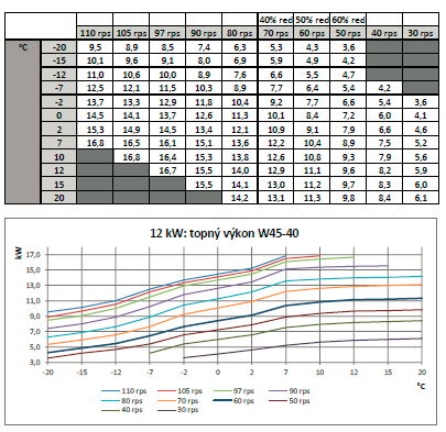
12kW Vaillant is v conservatively rated so good for a lot more: Don't know about the Mitsi but @JohnMo can probably tell us.
-
12kW Vaillant is v conservatively rated so good for a lot more, don't know about the Mitsi but @JohnMo can probably tell us.
-
HG cheat sheet suggests 30 - 50 W/m^2 so 11.2 to 14 kW, Vaillant 12kW sounds a good match. The 10kW is basically the same unit so has the same minimum output. 2023 of course.